Page 378 of 4731
DISASSEMBLY AT-295
D E
F
G H
I
J
K L
M A
B
AT
Revision: 2005 July 2005 FX
23. Remove high and low reverse clutch assembly from direct clutch
assembly.
CAUTION:
Make sure that needle bearing is installed to the high and
low reverse clutch assembly edge surface.
24. Remove direct clutch assembly from reverse brake.
25. Remove needle bearing from drum support.
26. Remove snap ring from A/T assembly harness connector.
27. Push A/T assembly harness connector. CAUTION:
Be careful not to damage connector.
SCIA2306E
SCIA5019E
SCIA5198E
SCIA5021E
SCIA5022E
Page 385 of 4731

AT-302
DISASSEMBLY
Revision: 2005 July 2005 FX
48. Remove needle bearing from transmission case.
49. Remove revolution sensor from transmission case. CAUTION:
�Do not subject it to impact by dropping or hitting it.
�Do not disassemble.
�Do not allow metal filings, etc. to get on the sensor's front
edge magnetic area.
�Do not place in an area affected by magnetism.
50. Remove reverse brake snap ring (fixing plate) using 2 flat- bladed screwdrivers.
NOTE:
Press out snap ring from the transmission case oil pan side gap
using a flat-bladed screwdriver, and remove it using another
screwdriver.
51. Remove reverse brake retaining plate from transmission case.
�Check facing for burns, cracks or damage. If necessary,
replace the plate.
52. Remove N-spring from transmission case.
53. Remove reverse brake drive plates, driven plates and dish plate from transmission case.
�Check facing for burns, cracks or damage. If necessary,
replace the plate.
SCIA5031E
SCIA2320E
SCIA5032E
SCIA5214E
SCIA2322E
Page 387 of 4731
AT-304
DISASSEMBLY
Revision: 2005 July 2005 FX
58. Remove reverse brake piston from transmission case with com-
pressed air. Refer to AT- 2 8 6 , "
Oil Channel" .
CAUTION:
Care should be taken not to abruptly blow air. It makes pis-
tons incline, as the result, it becomes hard to disassemble
the pistons.
59. Remove D-rings from reverse brake piston.
60. Use a pin punch (4mm dia. commercial service tool) to knock out retaining pin.
61. Remove manual shaft retaining pin with nippers.
SCIA5047E
SCIA5340E
SCIA2328E
SCIA2329E
Page 413 of 4731
AT-330
ASSEMBLY
Revision: 2005 July 2005 FX
9. Install return spring to servo assembly.
10. Install servo assembly in transmission case.
11. Using snap ring pliers, install snap ring to transmission case.
12. Install D-rings in reverse brake piston.
CAUTION:
�Do not reuse D-rings.
�Apply ATF to D-rings.
13. Install reverse brake piston in transmission case.
SCIA5717E
SCIA5679E
SCIA2333E
SCIA5340E
SCIA2325E
Page 415 of 4731
AT-332
ASSEMBLY
Revision: 2005 July 2005 FX
18. Install reverse brake drive plates, driven plates and dish plate in
transmission case.
CAUTION:
Take care with order of plates.
19. Assemble N-spring.
20. Install reverse brake retaining plate in transmission case.
21. Install snap ring in transmission case.
SCIA5250E
SCIA3179E
SCIA2439E
Page 416 of 4731
ASSEMBLY AT-333
D E
F
G H
I
J
K L
M A
B
AT
Revision: 2005 July 2005 FX
22. Measure clearance between retaining plate and snap ring. If not
within specified clearance, select proper retaining plate.
23. Install needle bearing to transmission case. CAUTION:
Apply petroleum jelly to needle bearing.
24. Install revolution sensor to transmission case. CAUTION:
�Do not subject it to impact by dropping or hitting it.
�Do not disassemble.
�Do not allow metal filings, etc., to get on the sensor's
front edge magnetic area.
�Do not place in an area affected by magnetism.
25. As shown in the figure, use the drift to drive rear oil seal into the rear extension (2WD models) or adapter case (AWD models)
until it is flush.
CAUTION:
�Apply ATF to rear oil seal.
�Do not reuse rear oil seal. Specified clearance “A”:
Standard: 0.7 - 1.1mm (0.028 - 0.043 in)
Retaining plate: Refer to AT- 3 5 3 , "
Reverse Brake" .
SCIA3129E
SCIA5031E
: 5.8 N·m (0.59 kg-m, 51 in-lb)
SCIA2320E
SCIA5477E
Page 420 of 4731
ASSEMBLY AT-337
D E
F
G H
I
J
K L
M A
B
AT
Revision: 2005 July 2005 FX
iii. Tighten adapter case assembly mounting bolts (1) to specified
torque. [With bracket (2).]
: Bolt (10)
CAUTION:
Do not reuse self-sealing bolts (3).
Refer to GI section to mark sure icons (symbol marks) in the fig-
ure. Refer to GI-10, "
Components" .
35. Install needle bearing in drum support. CAUTION:
Apply petroleum jelly to needle bearing.
36. Install direct clutch assembly in reverse brake. CAUTION:
Make sure that drum support edge surface and direct clutch
inner boss edge surface come to almost same place.
37. Install high and low reverse clutch assembly in direct clutch. Adapter case assembly mounting bolt:
: 52 N·m (5.3 kg-m, 38 ft-lb)
Self-sealing bolt: : 61 N·m (6.2 kg-m, 45 ft-lb)
SCIA7210E
SCIA5198E
SCIA5019E
SCIA2306E
Page 423 of 4731
AT-340
ASSEMBLY
Revision: 2005 July 2005 FX
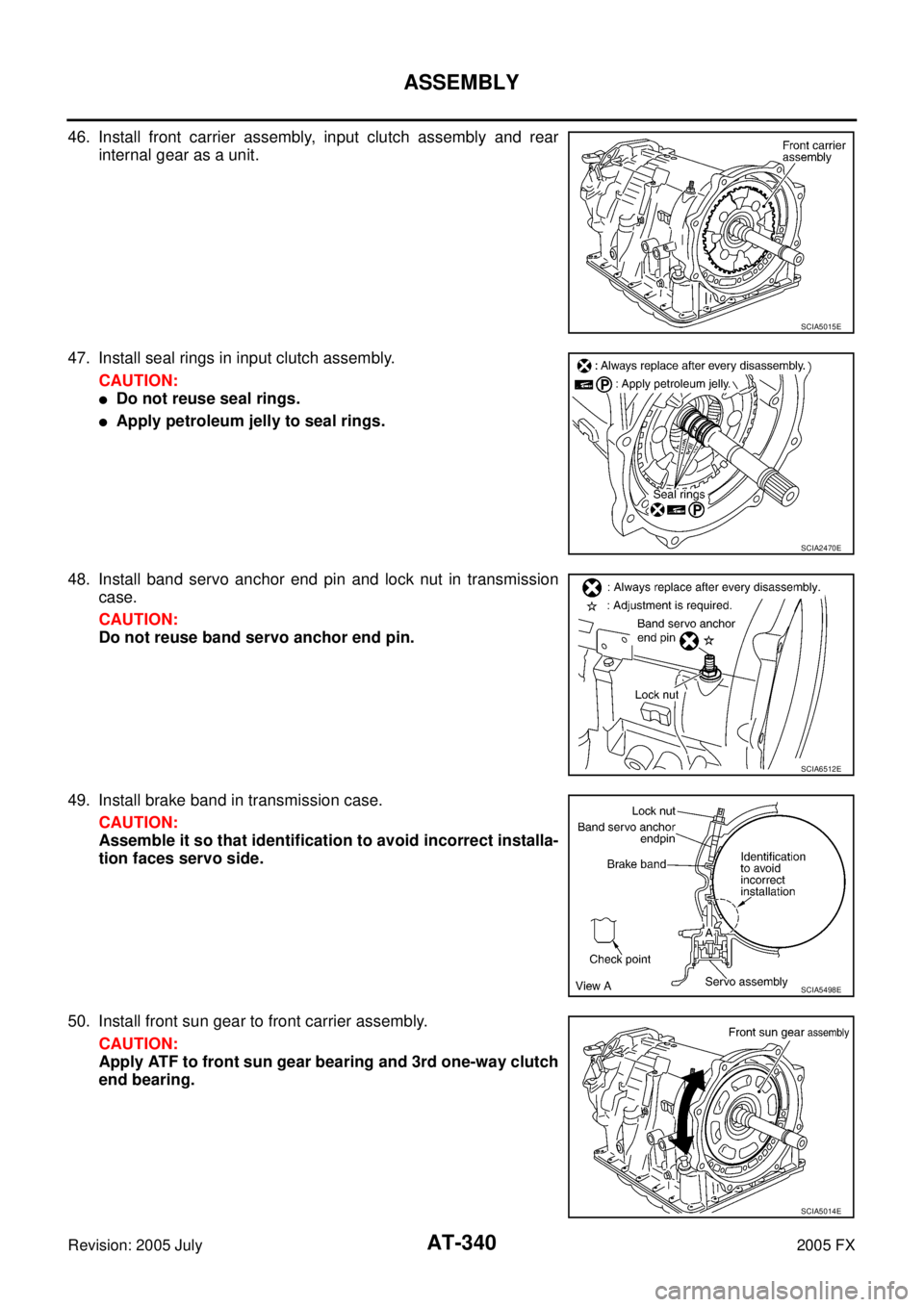
46. Install front carrier assembly, input clutch assembly and rear
internal gear as a unit.
47. Install seal rings in input clutch assembly. CAUTION:
�Do not reuse seal rings.
�Apply petroleum jelly to seal rings.
48. Install band servo anchor end pin and lock nut in transmission case.
CAUTION:
Do not reuse band servo anchor end pin.
49. Install brake band in transmission case. CAUTION:
Assemble it so that identification to avoid incorrect installa-
tion faces servo side.
50. Install front sun gear to front carrier assembly. CAUTION:
Apply ATF to front sun gear bearing and 3rd one-way clutch
end bearing.
SCIA5015E
SCIA2470E
SCIA6512E
SCIA5498E
SCIA5014E


![INFINITI FX35 2005 Service Manual ASSEMBLY AT-337
D E
F
G H
I
J
K L
M A
B
AT
Revision: 2005 July 2005 FX
iii. Tighten adapter case assembly mounting bolts (1) to specified
torque. [With bracket (2).]
: Bolt (10)
CAUTION](/manual-img/42/57020/w960_57020-419.png "INFINITI FX35 2005 Service Manual ASSEMBLY AT-337
D E
F
G H
I
J
K L
M A
B
AT
Revision: 2005 July 2005 FX
iii. Tighten adapter case assembly mounting bolts (1) to specified
torque. [With bracket (2).]
: Bolt (10)
CAUTION")