Page 3163 of 4731
ADS0019P
COMPONENTS
REMOVAL
1. Remove three engine mounting b")
FFD-12
FRONT FINAL DRIVE ASSEMBLY
Revision: 2005 July 2005 FX
FRONT FINAL DRIVE ASSEMBLYPFP:38500
Removal and Installation (VQ35DE Models)ADS0019P
COMPONENTS
REMOVAL
1. Remove three engine mounting bracket upper bolts. Refer to EM-117, "Components (AWD Model)" .
2. Remove three way catalyst (right bank). Refer to EM-26, "
EXHAUST MANIFOLD AND THREE WAY CAT-
ALYST" .
3. Remove stabilizer assembly with power tool. Refer to FSU-16, "
STABILIZER BAR" .
4. Remove steering gearbox mounting bolts with power tool. Refer to PS-19, "
POWER STEERING GEAR
AND LINKAGE" .
5. Remove front drive shaft both. Refer to FAX-12, "
FRONT DRIVE SHAFT" .
6. Remove side shaft assembly.
7. Remove front propeller shaft. Refer to PR-4, "
FRONT PROPELLER SHAFT" .
8. Remove front suspension member with power tool. Refer to FSU-17, "
FRONT SUSPENSION MEMBER" .
9. Remove breather hose and tube.
10. Remove mounting bolts and remove front final drive assembly from the vehicle.
INSTALLATION
Note the following, and installation is in the reverse order of removal.
�Refer to FFD-12, "COMPONENTS" about each tightening torque.
�When installing the side shaft, apply multi-purpose grease to contact surface of side shaft and side shaft
oil seal.
1. Front final drive assembly 2. Side shaft 3. Bushing
4. Front propeller shaft 5. Breather hose 6. Breather tube
7. Breather connector 8. Engine mounting bracket 9. Insulator
PDIA0658E
Page 3165 of 4731
ADS0019Q
COMPONENTS
REMOVAL
1. Remove three way catalyst (right bank). Refer to EM-182, \"EXHAUST")
FFD-14
FRONT FINAL DRIVE ASSEMBLY
Revision: 2005 July 2005 FX
Removal and Installation (VK45DE Models)ADS0019Q
COMPONENTS
REMOVAL
1. Remove three way catalyst (right bank). Refer to EM-182, "EXHAUST MANIFOLD AND THREE WAY
CATALYST" .
2. Remove stabilizer assembly with power tool. Refer to FSU-16, "
STABILIZER BAR" .
3. Remove steering gearbox mounting bolts with power tool. Refer to PS-19, "
POWER STEERING GEAR
AND LINKAGE" .
4. Remove front drive shaft both. Refer to FAX-12, "
FRONT DRIVE SHAFT" .
5. Remove side shaft assembly.
6. Remove front propeller shaft. Refer to PR-4, "
FRONT PROPELLER SHAFT" .
7. Remove front suspension member with power tool. Refer to FSU-17, "
FRONT SUSPENSION MEMBER" .
8. Remove engine wire harness clamp bolts from front final drive.
9. Remove breather hose and tube.
10. Remove mounting bolts and remove front final drive assembly from the vehicle.
INSTALLATION
Note the following, and installation is in the reverse order of removal.
�Refer to FFD-14, "COMPONENTS" about each tightening torque.
�When installing side shaft, apply multi-purpose grease to contact surface of side shaft and side shaft oil
seal.
1. Front final drive assembly 2. Side shaft 3. Bushing
4. Front propeller shaft 5. Breather tube 6. Breather hose
7. Breather connector 8. Harness bracket
PDIA0659E
Page 3207 of 4731
FSU-4
PREPARATION
Revision: 2005 July 2005 FX
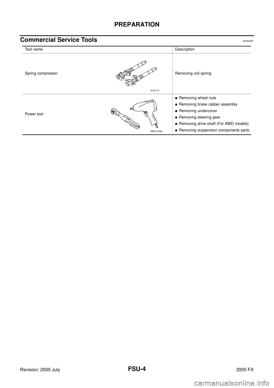
Commercial Service ToolsAES000N1
Tool nameDescription
Spring compressor Removing coil spring
Power tool
�Removing wheel nuts
�Removing brake caliper assembly
�Removing undercover
�Removing steering gear
�Removing drive shaft (For AWD models)
�Removing suspension components parts
S-NT717
PBIC0190E
Page 3212 of 4731

FRONT SUSPENSION ASSEMBLY FSU-9
C
D
F
G H
I
J
K L
M A
B
FSU
Revision: 2005 July 2005 FX
Removal and InstallationAES000N6
REMOVAL
1. Set an engine slinger to engine, then suspend engine.
2. Remove tire from vehicle with power tool.
3. Remove brake caliper with power tool. Hang it in a place where it will not interfere with work. Refer to BR-
20, "FRONT DISC BRAKE" .
4. Remove brake hose lock plate. Then remove brake hose from strut assembly.
5. Remove disc rotor.
6. Remove wheel sensor harness from strut assembly. CAUTION:
Do not pull on wheel sensor harness.
7. Remove undercover with power tool.
8. Remove front cross bar.
9. Remove steering hydraulic piping bracket from front suspension member. Refer to PS-41, "
HYDRAULIC LINE" .
10. Remove cotter pin at steering outer socket, then loosen mount- ing nut.
11. Use a ball joint remover (SST) to remove steering outer socket from steering knuckle. Be careful not to damage ball joint boot.
CAUTION:
Tighten temporarily mounting nut to prevent damage to
threads and to prevent ball joint remover (SST) from com-
ing off.
12. Remove mounting bolts of steering gear with power tool, then hang steering gear on vehicle. Refer to PS-19, "
POWER
STEERING GEAR AND LINKAGE" .
13. Remove front final drive side of drive shaft with power tool. (For AWD models) Refer to FAX-12, "
Removal and Installation (Left
Side)" , FA X - 1 3 , "Removal and Installation (Right Side)" .
14. Set jack under front suspension member.
15. Remove fixing bolts and nuts between strut assembly and steering knuckle with power tool.
1. Strut upper plate 2. Strut spacer 3. Mounting insulator
4. Mounting insulator bracket 5. Mounting bearing 6. Spring upper seat
7. Spring upper rubber seat 8. Coil spring 9. Spring lower rubber seat
10. Bound bumper 11. Strut 12. Steering knuckle
13. Front suspension member 14. Transverse link 15. Stabilizer bar
16. Stabilizer bushing 17. Stabilizer clamp 18. Stabilizer connecting rod
19. Front cross bar 20. Cotter pin
SEIA0328E
SEIA0329E
SDIA1434E
Page 3213 of 4731

FSU-10
FRONT SUSPENSION ASSEMBLY
Revision: 2005 July 2005 FX
16. Remove stabilizer connecting rod upper nut with power tool,
separate stabilizer connecting rod and strut assembly.
17. Remove mounting nuts between engine mounting insulator and front suspension member.
18. Remove mounting bolts which are at the back of transverse link (mounting part with body) with power tool, separate transverse
link.
19. Remove mounting nuts between front suspension member and body with power tool.
20. Move jack down slowly to remove front suspension member, transverse link, stabilizer bar, drive shaft (For AWD models) and
steering knuckle from vehicle as a unit.
21. Remove transverse link from steering knuckle. Refer to FSU-14,
"TRANSVERSE LINK" .
INSTALLATION
�Refer to FSU-8, "Components" for tightening torque. Install in the reverse order of removal.
NOTE:
Refer to component parts location and do not reuse non-reusable parts.
�After removing/installing or replacing suspension components and steering components, check wheel
alignment. Refer to FSU-6, "
Wheel Alignment Inspection" .
�After adjusting wheel alignment, adjust neutral position of steering angle sensor. Refer to BRC-6, "Adjust-
ment of Steering Angle Sensor Neutral Position" .
�Check the following item after service.
–Installation condition of wheel sensor harness.
SEIA0330E
SEIA0331E
Page 3214 of 4731

COIL SPRING AND STRUT FSU-11
C
D
F
G H
I
J
K L
M A
B
FSU
Revision: 2005 July 2005 FX
COIL SPRING AND STRUTPFP:55302
Removal and InstallationAES000N7
REMOVAL
1. Remove tire from vehicle with power tool.
2. Remove brake hose lock plate. Then remove brake hose from strut assembly.
3. Remove wheel sensor harness from strut assembly. CAUTION:
Do not pull wheel sensor harness.
4. Remove stabilizer connecting rod upper nut with power tool, separate stabilizer connecting rod and strut assembly.
5. Remove fixing bolts and nuts between strut assembly and steer- ing knuckle with power tool.
6. Remove mounting nuts on mounting insulator bracket with power tool, then remove strut upper plate, strut spacer and strut
from vehicle.
INSTALLATION
�Refer to FSU-8, "Components" for tightening torque. Install in the reverse order of removal.
NOTE:
Refer to component parts location and do not reuse non-reusable parts.
�After removing/installing or replacing suspension components, check wheel alignment. Refer to FSU-6,
"Wheel Alignment Inspection" .
�After adjusting wheel alignment, adjust neutral position of steering angle sensor. Refer to BRC-6, "Adjust-
ment of Steering Angle Sensor Neutral Position" .
�Check the following item after service.
–Installation condition of wheel sensor harness.
SEIA0328E
SEIA0329E
SEIA0330E
Page 3217 of 4731

FSU-14
TRANSVERSE LINK
Revision: 2005 July 2005 FX
TRANSVERSE LINKPFP:54500
Removal and InstallationAES000N9
REMOVAL
1. Remove tire from vehicle with power tool.
2. Remove undercover with power tool.
3. Remove front cross bar.
4. Remove cotter pin at transverse link, then loosen mounting nut.
5. Use a ball joint remover (SST) to remove transverse link from steering knuckle. Be careful not to damage ball joint boot.
CAUTION:
Tighten temporarily mounting nut to prevent damage to
threads and to prevent ball joint remover (SST) from com-
ing off.
6. Remove mounting bolts which are at the back of transverse link (mounting part with body) with power tool, separate transverse
link.
7. Remove mounting bolts which are at the front of transverse link (mounting part with front suspension member) with power tool,
separate transverse link.
8. Remove transverse link from vehicle.
INSPECTION AFTER REMOVAL
Visual Inspection
�Check transverse link and bushing for deformation, cracks, or damage. If any non-standard condition is
found, replace it.
�Check boot of ball joint for cracks, or other damage, and also for grease leakage. If any non-standard con-
dition is found, replace it.
Ball Joint Inspection
Manually move ball stud to confirm it moves smoothly with no binding.
SDIA1435E
SEIA0331E
Page 3219 of 4731

FSU-16
STABILIZER BAR
Revision: 2005 July 2005 FX
STABILIZER BARPFP:54611
Removal and InstallationAES000NA
REMOVAL
1. Remove tire from vehicle with power tool.
2. Remove undercover with power tool.
3. Remove stabilizer connecting rod lower nut with power tool, sep- arate stabilizer bar and stabilizer connecting rod.
4. Remove stabilizer clamp mounting bolts and nuts with power tool.
5. Remove stabilizer bar, stabilizer clamp, stabilizer bushing from vehicle.
6. Remove stabilizer connecting rod upper nut with power tool, separate stabilizer connecting rod and strut.
INSPECTION AFTER REMOVAL
Check stabilizer bar, stabilizer connecting rod, stabilizer bushing and stabilizer clamp deformation, cracks and
damage, and replace if necessary.
INSTALLATION
�Refer to FSU-8, "Components" for tightening torque. Install in the reverse order of removal.
NOTE:
Refer to component parts location and do not reuse non-reusable parts.
�After removing/installing or replacing suspension components, check wheel alignment. Refer to FSU-6,
"Wheel Alignment Inspection" .
�After adjusting wheel alignment, adjust neutral position of steering angle sensor. Refer to BRC-6, "Adjust-
ment of Steering Angle Sensor Neutral Position" .
�Stabilizer bar uses pillow ball type connecting rod. Position ball
joint with case on pillow ball head parallel to stabilizer bar.
SEIA0335E
SEIA0330E
SFA449BB