2005 Hyundai Terracan tow
[x] Cancel search: towPage 349 of 539
1CONTROLS AND EQUIPMENT
44
!WARNING:
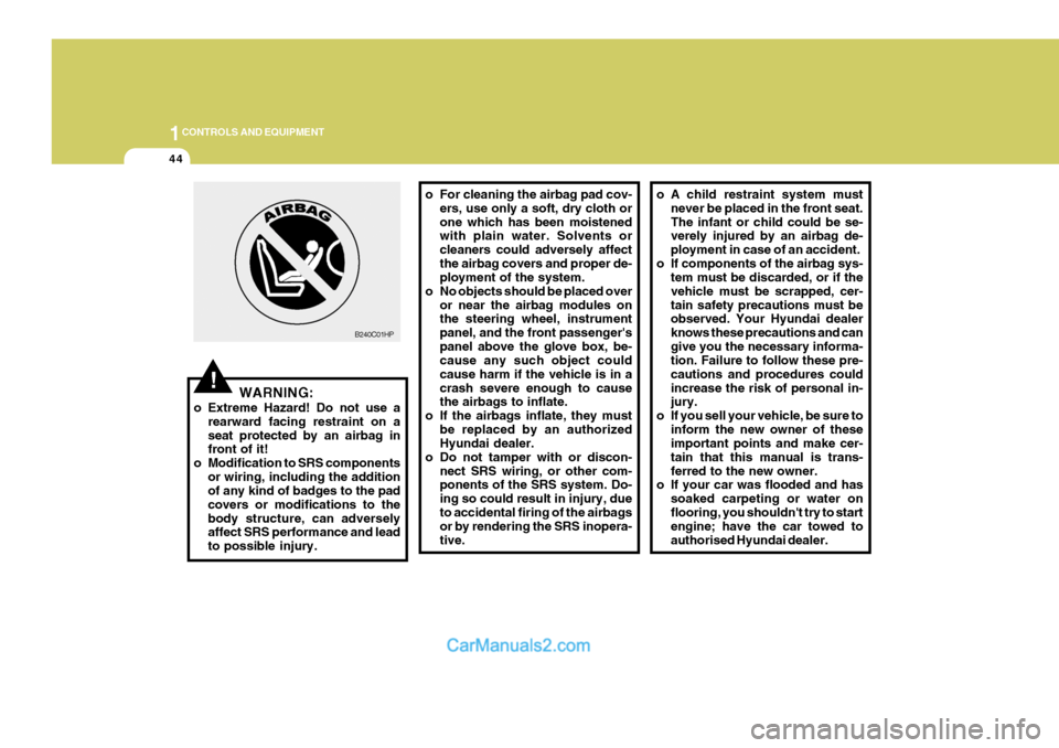
o Extreme Hazard! Do not use a rearward facing restraint on a seat protected by an airbag in front of it!
o Modification to SRS components
or wiring, including the additionof any kind of badges to the pad covers or modifications to thebody structure, can adversely affect SRS performance and lead to possible injury. o For cleaning the airbag pad cov-
ers, use only a soft, dry cloth orone which has been moistened with plain water. Solvents or cleaners could adversely affectthe airbag covers and proper de- ployment of the system.
o No objects should be placed over or near the airbag modules onthe steering wheel, instrument panel, and the front passenger'spanel above the glove box, be- cause any such object could cause harm if the vehicle is in acrash severe enough to cause the airbags to inflate.
o If the airbags inflate, they must be replaced by an authorizedHyundai dealer.
o Do not tamper with or discon- nect SRS wiring, or other com-ponents of the SRS system. Do- ing so could result in injury, dueto accidental firing of the airbags or by rendering the SRS inopera- tive.
B240C01HP
o A child restraint system must
never be placed in the front seat. The infant or child could be se- verely injured by an airbag de- ployment in case of an accident.
o If components of the airbag sys- tem must be discarded, or if thevehicle must be scrapped, cer-tain safety precautions must be observed. Your Hyundai dealer knows these precautions and cangive you the necessary informa- tion. Failure to follow these pre- cautions and procedures couldincrease the risk of personal in- jury.
o If you sell your vehicle, be sure to inform the new owner of theseimportant points and make cer- tain that this manual is trans-ferred to the new owner.
o If your car was flooded and has
soaked carpeting or water onflooring, you shouldn't try to start engine; have the car towed to authorised Hyundai dealer.
Page 356 of 539
1
CONTROLS AND EQUIPMENT
51
B260H02A-EAT
Parking Brake/ Low Brake Fluid LevelWarning Light WARNING:
In the event of problems being sus- pected with the braking system, theadvice of the nearest Hyundai dealer must be sought before the vehicle is driven. Driving the vehicle witheither an electrical or hydraulic brak- ing system defect may be danger- ous, resulting in accident or per-sonal injury. Warning Light Operation The parking brake/low brake fluid level warning light will be illuminated when-ever the ignition switch is turned to the "ON" position irrespective of whether or not the parking brake is applied andmust be extinguished when the engine starts and the parking brake released. If the warning light fails to extinguish orilluminates at any other time, the ve- hicle must be brought to rest in a safe location and the level of brake fluid inthe reservoir checked. If the fluid level is incorrect, fluid conforming to DOT 3 or DOT 4 specifications should beadded. If, after correcting the brake fluid level, the warning light continues to be illuminated, the advice of thenearest Hyundai dealer must be sought before the vehicle is driven again. Your Hyundai is equipped with a di-agonally split dual braking system which will ensure that in the event of one of the brake circuits becomingdefective, approximately fifty per cent of the normal braking performance will be available.If failure of one of the circuits occurs,the required amount of pedal effort,pedal travel and stopping distance will be increased. Use of the gearbox is recommended to assist in bringing thevehicle to rest. The vehicle must not be driven once brake failure has occurred until the system has been repaired andis functioning normally. The braking system employs a vacuum servo in order that the pedal efforts arereduced. Power for the servo is de- rived from the engine and therefore, in the event of the engine stopping or thevehicle being towed, pedal efforts will be substantially increased.
!
Page 361 of 539
1CONTROLS AND EQUIPMENT
56
!
B265B01HP-GAT
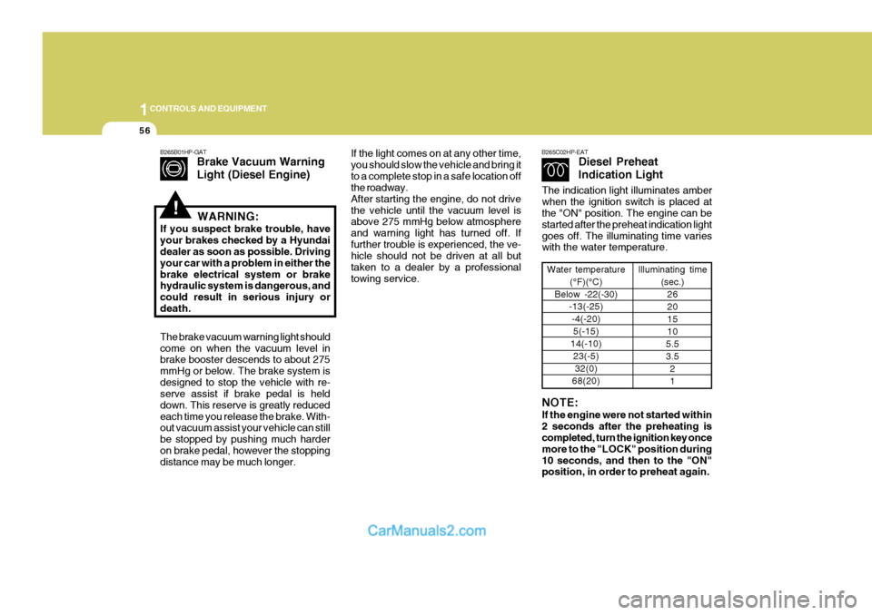
Brake Vacuum Warning Light (Diesel Engine)
The brake vacuum warning light should come on when the vacuum level in brake booster descends to about 275 mmHg or below. The brake system isdesigned to stop the vehicle with re- serve assist if brake pedal is held down. This reserve is greatly reducedeach time you release the brake. With- out vacuum assist your vehicle can still be stopped by pushing much harderon brake pedal, however the stopping distance may be much longer. WARNING:
If you suspect brake trouble, have your brakes checked by a Hyundai dealer as soon as possible. Driving your car with a problem in either thebrake electrical system or brake hydraulic system is dangerous, and could result in serious injury ordeath.If the light comes on at any other time, you should slow the vehicle and bring itto a complete stop in a safe location off the roadway. After starting the engine, do not drivethe vehicle until the vacuum level is above 275 mmHg below atmosphere and warning light has turned off. Iffurther trouble is experienced, the ve- hicle should not be driven at all but taken to a dealer by a professionaltowing service. B265C02HP-EAT
Diesel Preheat Indication Light
Water temperature
(°F)(°C)
Below -22(-30) -13(-25)
-4(-20)5(-15)
14(-10) 23(-5)32(0)
68(20) Illuminating time
(sec.)26 201510
5.53.5 21
NOTE: If the engine were not started within 2 seconds after the preheating is completed, turn the ignition key once more to the "LOCK" position during10 seconds, and then to the "ON" position, in order to preheat again.
The indication light illuminates amber when the ignition switch is placed at the "ON" position. The engine can be started after the preheat indication lightgoes off. The illuminating time varies with the water temperature.
Page 365 of 539
1CONTROLS AND EQUIPMENT
60
HPB220B1-E Lane Change Signal To indicate an intention to change lanes, moving the lever slightly towards the direction of the relevant turn signal will cause the turn signal lights to flash. Thelever will either return automatically or will need to be manually moved to the centre position when the lane changeindication has been completed.MULTI-FUNCTION SWITCH
ZB120A1-E Turn Signal Operation To signal an intention to turn right, the switch lever should be pressed down.To signal an intention to turn left, the switch lever should be pushed up- wards. In both instances, the turn sig-nal lamps on one side of the car will flash and the warning lamp located in the instrument cluster will flash in sym-pathy. Upon completion of the ma- noeuvre, the lever will, under normal circumstances, return to the "OFF"position. However, if the manoeuvre involved only a small movement of the steering wheel, the signal may need tobe cancelled manually. If either turn signal indicator flashes more rapidly than normal or refuses to flash at all, amalfunction of the turn signal system may exist.
HHP2099-E
B310A03HP-E
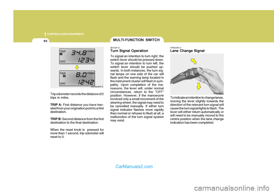
Trip odometer records the distance of 2 trips in miles. TRIP A: First distance you have trav-
eled from your origination point to a first destination. TRIP B: Second distance from the first
destination to the final destination.When the reset knob is pressed for more than 1 second, trip odometer will reset to 0.
Page 366 of 539
1
CONTROLS AND EQUIPMENT
61
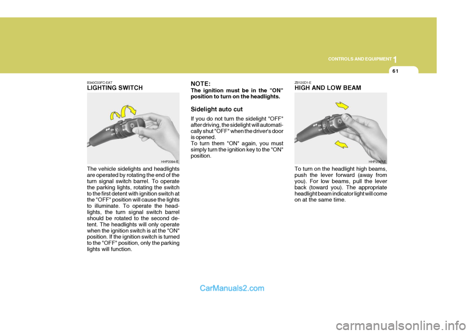
ZB120D1-E HIGH AND LOW BEAM
B340C03FC-EATLIGHTING SWITCH The vehicle sidelights and headlights are operated by rotating the end of the turn signal switch barrel. To operate the parking lights, rotating the switchto the first detent with ignition switch at the "OFF" position will cause the lights to illuminate. To operate the head-lights, the turn signal switch barrel should be rotated to the second de- tent. The headlights will only operatewhen the ignition switch is at the "ON" position. If the ignition switch is turned to the "OFF" position, only the parkinglights will function.
HHP2094-E NOTE: The ignition must be in the "ON" position to turn on the headlights. Sidelight auto cut If you do not turn the sidelight "OFF" after driving, the sidelight will automati-cally shut "OFF" when the driver's door is opened. To turn them "ON" again, you mustsimply turn the ignition key to the "ON" position.HHP2097-E
To turn on the headlight high beams, push the lever forward (away from you). For low beams, pull the lever back (toward you). The appropriateheadlight beam indicator light will come on at the same time.
Page 367 of 539
1CONTROLS AND EQUIPMENT
62FOG LIGHT SWITCH
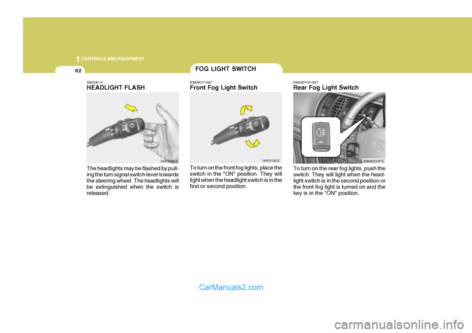
B360B01Y-AAT Front Fog Light Switch To turn on the front fog lights, place the switch in the "ON" position. They will light when the headlight switch is in thefirst or second position. B360A01HP-GAT Rear Fog Light Switch
HHP2100-E B360A01HP-E
SB220E1-EHEADLIGHT FLASH The headlights may be flashed by pull- ing the turn signal switch lever towards the steering wheel. The headlights will be extinguished when the switch isreleased.
HHP2098-E
To turn on the rear fog lights, push the switch. They will light when the head- light switch is in the second position or the front fog light is turned on and thekey is in the "ON" position.
Page 368 of 539
1
CONTROLS AND EQUIPMENT
63
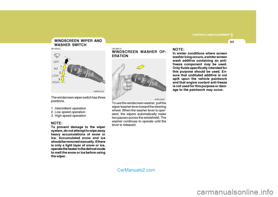
The windscreen wiper switch has three positions.
1. Intermittent operation
2. Low speed operation
3. High speed operation NOTE: To prevent damage to the wiper system, do not attempt to wipe awayheavy accumulations of snow or ice. Accumulated snow and ice should be removed manually. If thereis only a light layer of snow or ice, operate the heater in the defrost mode to melt the snow or ice before usingthe wiper.WINDSCREEN WIPER AND WASHER SWITCH
ZB130A2-E
HHP2101-E
1
OB130B1-E WINDSCREEN WASHER OP- ERATION To use the windscreen washer, pull the wiper/washer lever toward the steeringwheel. When the washer lever is oper- ated, the wipers automatically make two passes across the windshield. Thewasher continues to operate until the lever is released. NOTE: In winter conditions where screen washer icing occurs, a winter screen wash additive containing an anti-freeze component may be used. Only fluids specifically intended for this purpose should be used. En-sure that undiluted additive is not spilt upon the vehicle paintwork and that engine coolant anti-freezeis not used for this purpose or dam- age to the paintwork may occur.
HHP2103-E
2 3
Page 382 of 539
1
CONTROLS AND EQUIPMENT
77
!
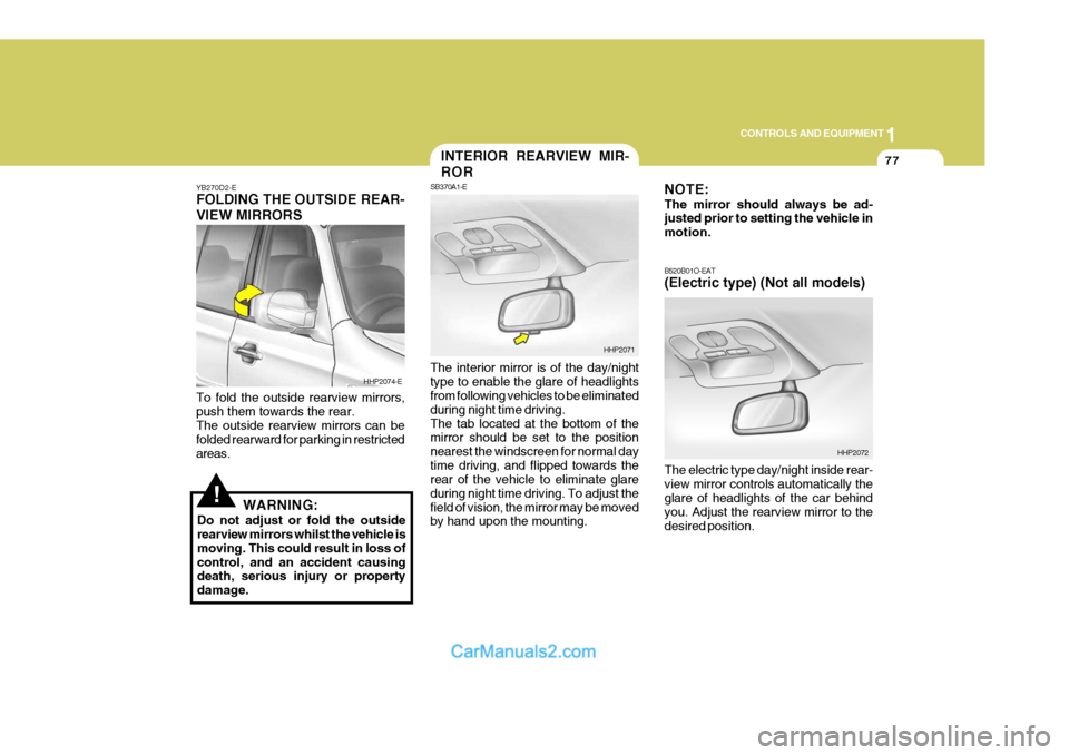
YB270D2-E FOLDING THE OUTSIDE REAR- VIEW MIRRORS To fold the outside rearview mirrors, push them towards the rear. The outside rearview mirrors can be folded rearward for parking in restrictedareas.
WARNING:
Do not adjust or fold the outside rearview mirrors whilst the vehicle is moving. This could result in loss ofcontrol, and an accident causing death, serious injury or property damage. The interior mirror is of the day/nighttype to enable the glare of headlights from following vehicles to be eliminated during night time driving.The tab located at the bottom of the mirror should be set to the position nearest the windscreen for normal daytime driving, and flipped towards the rear of the vehicle to eliminate glare during night time driving. To adjust thefield of vision, the mirror may be moved by hand upon the mounting.
HHP2074-E
HHP2071
INTERIOR REARVIEW MIR- ROR
SB370A1-E NOTE: The mirror should always be ad- justed prior to setting the vehicle in motion. B520B01O-EAT (Electric type) (Not all models) The electric type day/night inside rear- view mirror controls automatically the glare of headlights of the car behind you. Adjust the rearview mirror to thedesired position.
HHP2072