Page 502 of 539
6
OWNER MAINTENANCE
25
!
!
1. Loosen the adusting bolts just
enough so that the components can be moved.
2. Whilst pulling outward on the pry bar
or screwdriver, test the belt deflec-tion with your thumb.
3. After tightening the adjusting bolts, be sure to recheck the belt tension. Overtightening drive belts can cause excessive wear and failurein driven components and belts.
WARNING:
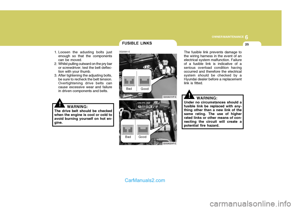
The drive belt should be checked when the engine is cool or cold to avoid burning yourself on hot en-gine. The fusible link prevents damage tothe wiring harness in the event of anelectrical system malfunction. Failure of a fusible link is indicative of a serious overload condition havingoccurred and therefore the electrical system should be checked by a Hyundai dealer before a replacementlink is fitted.
WARNING:
Under no circumstances should afusible link be replaced with any- thing other than a new link of the same rating. The use of higherrated links or other means of con- necting the circuit will create a potential fire hazard.
FUSIBLE LINKS
DG200A1-E
G200A01HP-E
Bad
Good
G200A02HP-E
Bad Good
Page 505 of 539
6 OWNER MAINTENANCE
28
!WARNING:
The cooling fan is controlled by engine coolant temperature and may sometimes operate even when the engine is not running. Do not touchthe radiator fan until it is completely stopped. As the coolant temperature de- creases the fan will automatically shut off. This is a normal condi-tion.
Checking Engine Cooling Fan The engine cooling fan should auto-matically come on if the engine cool- ant temperature is high.
Checking Condenser Cooling Fan The condenser cooling fan (in front of the condenser) should come on auto- matically whenever the air conditioner is in operation.
If any electrolyte gets into your eyes, flush your eyes with clean water for at least 15 minutes and get imme-diate medical attention. If possible, continue to apply water with a sponge orcloth until medical atten- tion is received. If electrolyte gets on your skin, thoroughly wash the contacted area. If you feel a pain or a burn- ing sensation, get medical attention immediately.Wear eye protection whencharging or working near abattery.Always provide ventilationwhen working in an en- closed space.o When lifting a plastic-cased bat- tery, excessive pressure on the case may cause battery acid to leak, resulting in personal injury.Lift with a battery carrier or with your hands on opposite corners.
o Never attempt to charge the bat- tery when the battery cables are connected.
o The electrical ignition system works with high voltage. Never touch these components with the engine running or the ignition switched on.
CHECKING ELECTRIC COOLING FANS
YG210A1-E
Page 506 of 539
6
OWNER MAINTENANCE
29
YG220A1-E POWER STEERING HOSES It is suggested that you check the power steering hose connections forfluid leakage at those intervals speci- fied in the vehicle maintenance sched- ule in Section 5. The power steeringhoses should be replaced if there are severe surface cracking, pulling, scuff- ing or worn spots. Deterioration of thehoses could cause premature failure. NOTE: The power steering pump may be noisy when the engine is first started in the extreme cold (-4°F).This noise is not abnormal and will stop as the engine warms up. If the power steering pump contin-ues to be noisy after the engine has warmed up, have it inspected by your Authorised Hyundai Dealer.
The power steering fluid level should
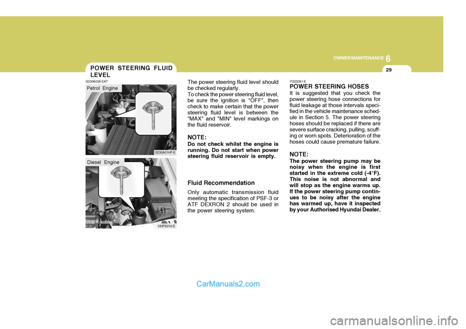
be checked regularly.
To check the power steering fluid level,
be sure the ignition is "OFF", thencheck to make certain that the powersteering fluid level is between the "MAX" and "MIN" level markings on the fluid reservoir.
NOTE: Do not check whilst the engine is
running. Do not start when power steering fluid reservoir is empty. Fluid Recommendation
Only automatic transmission fluid meeting the specification of PSF-3 orATF DEXRON 2 should be used in the power steering system.POWER STEERING FLUID LEVEL
G230A03A-EAT
Petrol Engine
G230A01HP-E
HHP5014-E
Diesel Engine
Page 507 of 539
6 OWNER MAINTENANCE
30
!
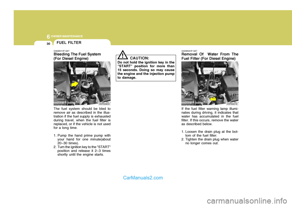
The fuel system should be bled to remove air as described in the illus- tration if the fuel supply is exhausted during travel, when the fuel filter isreplaced, or if the vehicle is not used for a long time.
1. Pump the hand prime pump with your hand for one minute(about 20~30 times).
2. Turn the ignition key to the "START" position and release it 2~3 times shortly until the engine starts. CAUTION:
Do not hold the ignition key in the
"START" position for more than 15 seconds. Doing so may causethe engine and the injection pump to damage. G300B02HP-GAT
Removal Of Water From The Fuel Filter (For Diesel Engine)
If the fuel filter warning lamp illumi-
nates during driving, it indicates that water has accumulated in the fuel filter. If this occurs, remove the wateras described below.
1. Loosen the drain plug at the bot- tom of the fuel filter.
2. Tighten the drain plug when water no longer comes out.
FUEL FILTER
G350B01HP-GAT Bleeding The Fuel System (For Diesel Engine)
HHP5048-EHHP5047-E
Page 508 of 539
6
OWNER MAINTENANCE
31
!
!
3. Check to be sure that the warning
lamp illuminates when the ignition key is turned to "ON", and that it goes off when the engine is started. If in doubt, consult your nearest authorised HYUNDAI dealer.
NOTE: It is recommended that water accu- mulated in the fuel filter should be removed by an authorised Hyundai dealer.
WARNING:
Be sure to carefully wipe away anywater drained out in this manner, because the fuel mixed in the water might be ignited and resultin a fire. Before attempting to replace a head-
light bulb, be sure the switch is turned to the "OFF" position.
The next paragraph shows how to
reach the headlight bulbs so they may be changed. Be sure to replacethe burned-out bulb with one of the same number and wattage rating.
Ensure that the replacement bulb has
the same cap configuration and watt-age as the original.
See page 6-35 for the wattage descrip-
tions.
CAUTION:
Keep the lamps out of contact with
petroleum product, such as oil, petrol, etc.
REPLACING HEADLIGHT BULBS
G260A01HP-EAT
G270A01B-EAT Headlight Bulb
1. Allow the bulb to cool. Wear eye
protection.
2. Open the engine bonnet.
3. Always grasp the bulb by its plas- tic base, avoid touching the glass.
4. Using a spanner, remove the head- light assembly mounting bolts.
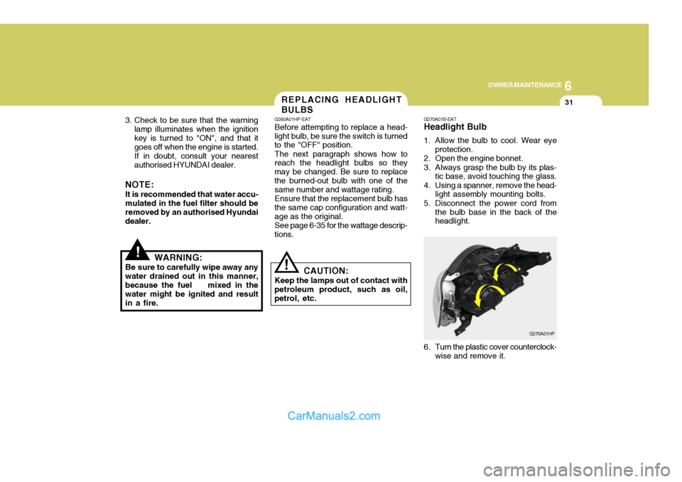
5. Disconnect the power cord from the bulb base in the back of the headlight.
G270A01HP
6. Turn the plastic cover counterclock- wise and remove it.
Page 510 of 539
6
OWNER MAINTENANCE
33
And then, draw a parallel line at 1.50 in. (38 mm) under the horizontal line incase of adjusting the low beam or at 0.83 in. (21 mm) under the horizontal line in case of adjusting the high beam.
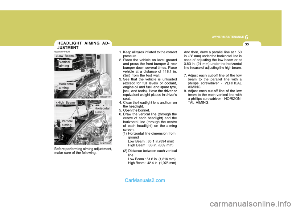
7. Adjust each cut-off line of the low beam to the parallel line with a phillips screwdriver - VERTICAL AIMING.
8. Adjust each cut-off line of the low beam to the each vertical line witha phillips screwdriver - HORIZON-TAL AIMING.
Before performing aiming adjustment,make sure of the following.HEADLIGHT AIMING AD- JUSTMENT
G290A01HP-EAT
1. Keep all tyres inflated to the correct
pressure.
2. Place the vehicle on level ground and press the front bumper & rear bumper down several times. Placevehicle at a distance of 118.1 in. (3m) from the test wall.
3. See that the vehicle is unloaded (except for full levels of coolant, engine oil and fuel, and spare tyre,jack, and tools). Have the driver or equivalent weight placed in driver's seat.
4. Clean the headlight lens and turn on the headlight.
5. Open the bonnet.
6. Draw the vertical line (through the centre of each headlight) and thehorizontal line (through the centre of each headlight) on the aiming screen.
(1) Horizontal line dimension from
Horizontal aiming
Vertical aiming
G290B01HP
G290B02HP
Horizontal aiming
Vertical aiming
ground : Low Beam : 35.1 in.(894 mm) High Beam : 33 in. (839 mm)
(2) Distance between each vertical line :Low Beam : 51.8 in. (1,316 mm) High Beam : 42.4 in. (1,076 mm)
Page 513 of 539
6 OWNER MAINTENANCE
36
NO.1
NO. 2
NO. 3
NO.4
NO.5
NO. 6
NO. 7
NO. 8
NO. 9
NO. 10
NO. 11
NO. 12
DESCRIPTION
G200C01HP-EAT Engine Compartment (#1)
G200C01HP-E
NOTE: Not all fuse panel descriptions in this manual may be applicable to your vehicle. It is accurate at the time of printing. When you inspect the fuse box on your vehicle, refer to the fuse box label. AMPERAGES
100A
120A (DIESEL)
140A ( PETROL)
50A 30A - -
20A 10A 15A -
10A10A CIRCUIT PROTECTED
Glow Relay (COVEC-F/EGR), Air Heater Relay (Diesel Engine) Engine Compartment Fuse & Relay Box #2,GeneratorInner Panel Fuse Box (Fuse 1,2,3,4,5)Engine Compartment Fuse & Relay Box #1 (Fuse 8,9)
Fuel Heater Control Module (COVEC-F/EGR)
Generator, Ignition Switch--Engine Control Relay (Diesel Engine), Main Control Relay
(Petrol Engine)
Horn Relay
Front Fog Lamp Relay-ECM (Diesel Engine), EGR Control ModuleECM (Diesel Engine)
FUSIBLE LINK
FUSE
FUSE PANEL DESCRIPTION
Petrol Engine Diesel Engine
Page 514 of 539
6
OWNER MAINTENANCE
37
NOTE: Not all fuse panel descriptions in this manual may be applicable to your vehicle. It is accurate at the time of printing. When you inspect the fuse box on your vehicle, refer to the fuse box label.
G200D01HP-EAT
Engine Compartment (#2)
G200C02HP