Page 366 of 539

1
CONTROLS AND EQUIPMENT
61
ZB120D1-E HIGH AND LOW BEAM
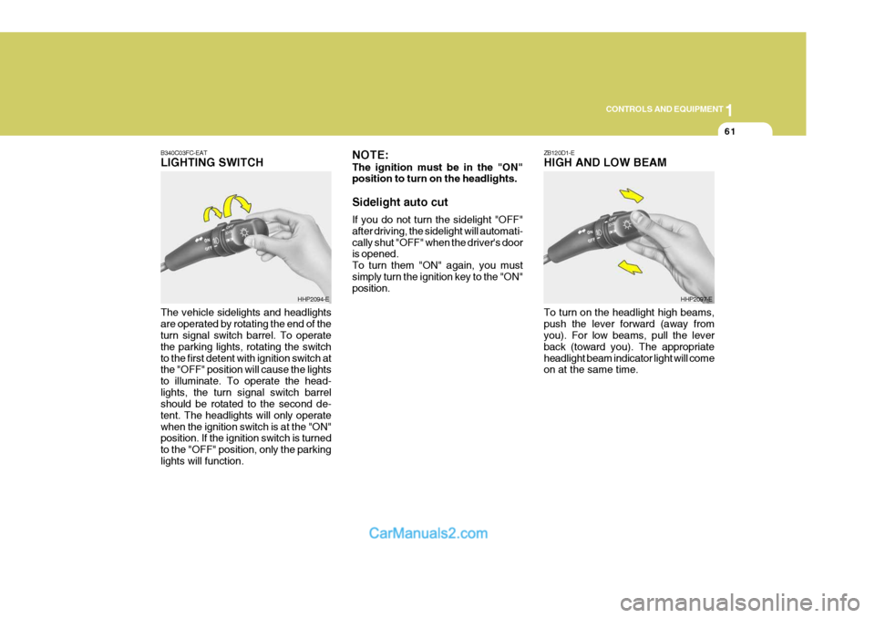
B340C03FC-EATLIGHTING SWITCH The vehicle sidelights and headlights are operated by rotating the end of the turn signal switch barrel. To operate the parking lights, rotating the switchto the first detent with ignition switch at the "OFF" position will cause the lights to illuminate. To operate the head-lights, the turn signal switch barrel should be rotated to the second de- tent. The headlights will only operatewhen the ignition switch is at the "ON" position. If the ignition switch is turned to the "OFF" position, only the parkinglights will function.
HHP2094-E NOTE: The ignition must be in the "ON" position to turn on the headlights. Sidelight auto cut If you do not turn the sidelight "OFF" after driving, the sidelight will automati-cally shut "OFF" when the driver's door is opened. To turn them "ON" again, you mustsimply turn the ignition key to the "ON" position.HHP2097-E
To turn on the headlight high beams, push the lever forward (away from you). For low beams, pull the lever back (toward you). The appropriateheadlight beam indicator light will come on at the same time.
Page 367 of 539
1CONTROLS AND EQUIPMENT
62FOG LIGHT SWITCH
B360B01Y-AAT Front Fog Light Switch To turn on the front fog lights, place the switch in the "ON" position. They will light when the headlight switch is in thefirst or second position. B360A01HP-GAT Rear Fog Light Switch
HHP2100-E B360A01HP-E
SB220E1-EHEADLIGHT FLASH The headlights may be flashed by pull- ing the turn signal switch lever towards the steering wheel. The headlights will be extinguished when the switch isreleased.
HHP2098-E
To turn on the rear fog lights, push the switch. They will light when the head- light switch is in the second position or the front fog light is turned on and thekey is in the "ON" position.
Page 382 of 539

1
CONTROLS AND EQUIPMENT
77
!
YB270D2-E FOLDING THE OUTSIDE REAR- VIEW MIRRORS To fold the outside rearview mirrors, push them towards the rear. The outside rearview mirrors can be folded rearward for parking in restrictedareas.
WARNING:
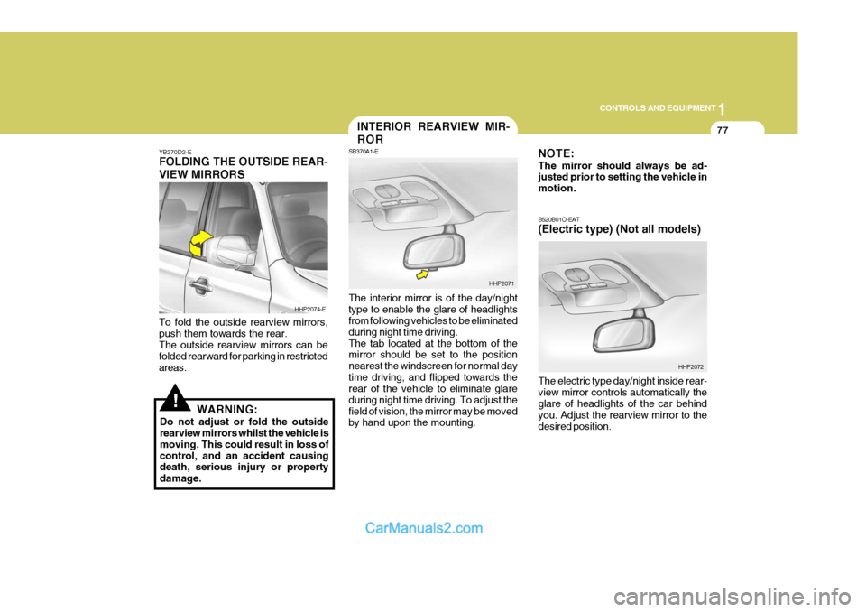
Do not adjust or fold the outside rearview mirrors whilst the vehicle is moving. This could result in loss ofcontrol, and an accident causing death, serious injury or property damage. The interior mirror is of the day/nighttype to enable the glare of headlights from following vehicles to be eliminated during night time driving.The tab located at the bottom of the mirror should be set to the position nearest the windscreen for normal daytime driving, and flipped towards the rear of the vehicle to eliminate glare during night time driving. To adjust thefield of vision, the mirror may be moved by hand upon the mounting.
HHP2074-E
HHP2071
INTERIOR REARVIEW MIR- ROR
SB370A1-E NOTE: The mirror should always be ad- justed prior to setting the vehicle in motion. B520B01O-EAT (Electric type) (Not all models) The electric type day/night inside rear- view mirror controls automatically the glare of headlights of the car behind you. Adjust the rearview mirror to thedesired position.
HHP2072
Page 511 of 539

6 OWNER MAINTENANCE
34
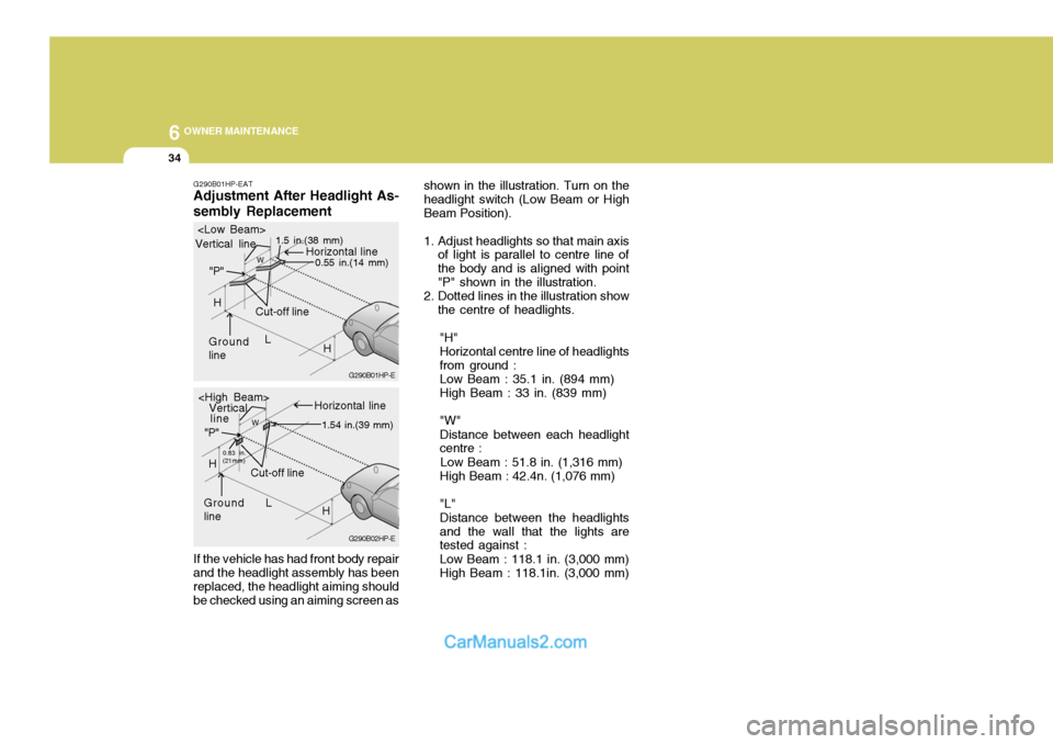
G290B01HP-EAT Adjustment After Headlight As- sembly Replacement If the vehicle has had front body repair and the headlight assembly has been replaced, the headlight aiming should be checked using an aiming screen as shown in the illustration. Turn on theheadlight switch (Low Beam or HighBeam Position).
1. Adjust headlights so that main axis
of light is parallel to centre line of the body and is aligned with point"P" shown in the illustration.
2. Dotted lines in the illustration show
the centre of headlights.
"H"Horizontal centre line of headlightsfrom ground : Low Beam : 35.1 in. (894 mm) High Beam : 33 in. (839 mm) "W" Distance between each headlight centre :
Low Beam : 51.8 in. (1,316 mm) High Beam : 42.4n. (1,076 mm) "L" Distance between the headlights and the wall that the lights are tested against : Low Beam : 118.1 in. (3,000 mm) High Beam : 118.1in. (3,000 mm)
G290B02HP-EG290B01HP-E
L
W
Cut-off line
Ground line "P"
Horizontal line
Vertical line
1.5 in.(38 mm)
0.55 in.(14 mm)
H
H
L
W
Cut-off line
Ground line "P"
Horizontal line
Vertical
0.83 in. (21mm) 1.54 in.(39 mm)
H
H
line