2005 Hyundai Matrix headlight
[x] Cancel search: headlightPage 132 of 407

OWNER MAINTENANCE 6-25
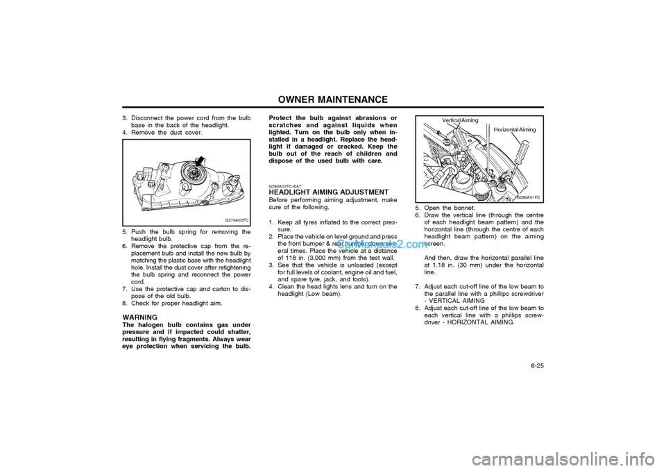
5. Push the bulb spring for removing the
headlight bulb.
6. Remove the protective cap from the re- placement bulb and install the new bulb by matching the plastic base with the headlighthole. Install the dust cover after retighteningthe bulb spring and reconnect the powercord.
7. Use the protective cap and carton to dis- pose of the old bulb.
8. Check for proper headlight aim.
WARNING The halogen bulb contains gas under
pressure and if impacted could shatter, resulting in flying fragments. Always weareye protection when servicing the bulb.
G270A02FC
3. Disconnect the power cord from the bulb base in the back of the headlight.
4. Remove the dust cover.
5. Open the bonnet.
6. Draw the vertical line (through the centreof each headlight beam pattern) and the horizontal line (through the centre of eachheadlight beam pattern) on the aimingscreen. And then, draw the horizontal parallel line at 1.18 in. (30 mm) under the horizontalline.
7. Adjust each cut-off line of the low beam to the parallel line with a phillips screwdriver- VERTICAL AIMING
8. Adjust each cut-off line of the low beam to each vertical line with a phillips screw-driver - HORIZONTAL AIMING.
G290A01FC-EAT
HEADLIGHT AIMING ADJUSTMENT
Before performing aiming adjustment, makesure of the following.
1. Keep all tyres inflated to the correct pres- sure.
2. Place the vehicle on level ground and press the front bumper & rear bumper down sev-eral times. Place the vehicle at a distanceof 118 in. (3,000 mm) from the test wall.
3. See that the vehicle is unloaded (except for full levels of coolant, engine oil and fuel,and spare tyre, jack, and tools).
4. Clean the head lights lens and turn on the headlight (Low beam).
G290A01FC
Horizontal Aiming
Vertical Aiming
Protect the bulb against abrasions or scratches and against liquids whenlighted. Turn on the bulb only when in-stalled in a headlight. Replace the head-light if damaged or cracked. Keep thebulb out of the reach of children anddispose of the used bulb with care.
Page 133 of 407

OWNER MAINTENANCE
6-26 SPECIFICATIONS: "H" Horizontal centre line of headlights from ground. : 26.8 in.(656 mm) "W" Distance between each headlight centre.: 47.7 in. (1,164 mm) "L" Distance between the headlights and thewall that the lights are tested against. : 118 in. (3,000 mm).
G290B01FC-EAT
Adjustment After Headlight Assembly Replacement
Horizontal line
If the vehicle has had front body repair and the
headlight assembly has been replaced, the headlight aiming should be checked using theaiming screen as shown in the illustration.Turn on the headlight switch. (Low BeamPosition)
1. Adjust headlights so that main axis of light is parallel to centre line of the body and is aligned with point "P" shown in the illustra-tion.
2. Dotted lines in the illustration show the centre of headlights. G290B01S-DAGVertical line
W
0.59 in. (15mm)"P" 1.18 in. (30mm)
Cut-off line
Ground line H
H L
Page 148 of 407

INDEX
10-2
E EFFECTIVE BRAKING
...................................................................... 2-9
ELECTRIC COOLING FANS ........................................................... 6-22
EMERGENCY TOWING ................... ...............................................3-10
EMISSION CONTROL SYSTEM ...................................................... 7-1
ENGINE COMPARTMENT ...................................................... 6-1 ~ 6-3
ENGINE COOLANT CHECKING AND REPLACING ....................... 6-9
ENGINE OIL AND FILTER REPLACEMENT ................................... 6-6
ENGINE OIL CONSUMPTION .......................................................... 6-6
ENGINE OIL REPLENISHMENT ...................................................... 6-5
ENGINE OIL ....................................................................................... 6-4
EXTERIOR REAR VIEW MIRR OR ................................................. 1-47
FFOLDING REAR SEATBACK AND SEAT CUSHION .......1-11 ~ 1-12
FOLD-UP TRAY ............................................................................... 1-50
FRONT ASHTRAY ........................................................................... 1-42
FRONT FOG LIGHT SWITCH ........................................................ 1-41
FUEL ECONOMY .............................................................................. 2-4
FUEL GAUGE .................................................................................. 1-35
FUEL RECOMMENDATIONS ........................................................... 1-1
FUSE PANEL DESCRIPTION ......................................................... 6-28
FUSIBLE LINKS ............................................................................... 6-20G GLOVE BOX
.................................................................................... 1-47
H HAZARD WARNING SYSTEM ........................................................ 1-40
HEADLIGHT AIMING ADJUSTEMENT ..........................................6-25
HEADLIGHT BULB ......................................................................... 6-24
HEADLIGHT LEVELING DEVICE SYSTEM ..................................1-44
HEAD RESTRAINT ADJUSTMENT ........................................ 1-9, 1-11
HEATED REAR WINDOW .............................................................. 1-41
HEATING CONTROL ....................................................................... 1-58
HEIGHT ADJUSTABLE FRONT SEAT SHOULDER BELT .......... 1-14
HORN ............................................................................................... 1-54
I
IF THE ENGINE CANNOT BE CRANKED ...................................... 3-1
IF THE ENGINE WILL NOT START ................................................ 3-1
IF THE EVENT OF A PUNCTURE ................................................... 3-4
IF YOUR VEHICLE MUST BE TOWED ........................................... 3-8
IMMOBILISER SYSTEM ......................................................... 1-2 ~ 1-3
INDIVIDUAL CIRCUIT FUSES ........................................................ 6-21
INSTRUMENT CLUSTER AND INDICATORS .............................. 1-30
INSTRUMENTS AND CONTROLS .................................................1-29
INTERIOR LIGHT ............................................................................ 1-46
INTERIOR REAR VIEW MIRROR .................................................. 1-49
Page 161 of 407

1. Front Fog Light Switch (If installed)
2. Headlight Leveling Switch (If installed)
3. Rear Fog Light Switch (If installed)
4. Multi-Function Light Switch
5. Indicator and Warning Light
6. Horn and Driver's Airbag (If installed)
7. Windshield Wiper/Washer Switch
8. Instrument Cluster
9. Hazard Warning Light
10.Heating/Air Conditioning Control Panel (If installed)
11.Audio System (If installed)
12.Accessory TrayCAUTION:
When installing a container of liquid air freshener inside the vehicle, do not place it near the instrument cluster nor on the instrument panel pad surface. If there is any leakage from the air freshener onto these areas (instrument cluster, instrument panel pad or air ventilator), it may damage these parts. If the liquid from the air freshener does leak onto these areas, washthem with water immediately.
! 13.Passenger's Airbag (If installed)
14.Passenger's Drink Holder
15.Hood Release Lever
16.Multi Box
17.Ashtray
18.Cigarette Lighter
19.Shift Lever (If installed)
20.Drink Holder
21.Parking Brake Lever
22.Glove Box
23.Center Console (If installed)
Page 163 of 407

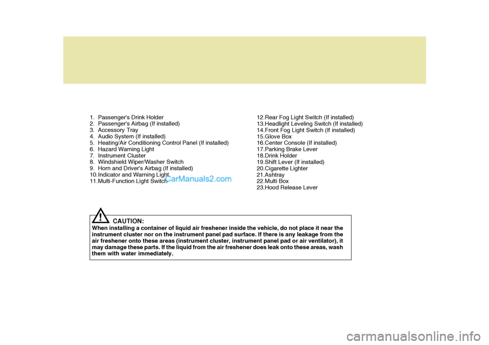
1. Passenger's Drink Holder
2. Passenger's Airbag (If installed)
3. Accessory Tray
4. Audio System (If installed)
5. Heating/Air Conditioning Control Panel (If installed)
6. Hazard Warning Light
7. Instrument Cluster
8. Windshield Wiper/Washer Switch
9. Horn and Driver's Airbag (If installed)
10.Indicator and Warning Light
11.Multi-Function Light SwitchCAUTION:
When installing a container of liquid air freshener inside the vehicle, do not place it near theinstrument cluster nor on the instrument panel pad surface. If there is any leakage from the air freshener onto these areas (instrument cluster, instrument panel pad or air ventilator), itmay damage these parts. If the liquid from the air freshener does leak onto these areas, wash them with water immediately.
! 12.Rear Fog Light Switch (If installed)
13.Headlight Leveling Switch (If installed)
14.Front Fog Light Switch (If installed)
15.Glove Box
16.Center Console (If installed)
17.Parking Brake Lever
18.Drink Holder
19.Shift Lever (If installed)
20.Cigarette Lighter
21.Ashtray
22.Multi Box
23.Hood Release Lever
Page 214 of 407

1FEATURES OF YOUR HYUNDAI
50
B260M01A-AAT
Low Fuel Level Warning
Light
The low fuel level warning light comes on when the fuel tank is approachingempty. When it comes on, you should add fuel as soon as possible. Driving with the fuel level warning light on orwith the fuel level below "E" can cause the engine to misfire and damage the catalytic converter. B260F01A-AAT High Beam Indicator
Light
The high beam indicator light comes on whenever the headlights are switched to the high beam or flash position.B260K01B-GAT Tail Gate Open Warning
Light
This light remains on unless the tail gate is completely closed. B260L01A-GAT Door Ajar Warning Light
The door ajar warning light warns you that a door is not completely closed.
B260G01A-AAT Low Oil Pressure
Warning Light
CAUTION:
If the oil pressure warning light stays on while the engine is run- ning, serious engine damage may result. The oil pressure warninglight comes on whenever there is insufficient oil pressure. In normal operation, it should come on whenthe ignition switch is turned on, then go out when the engine is started. If the oil pressure warning light stays on while the engine isrunning, there may be a serious malfunction. If this happens, stop the car assoon as it is safe to do so, turn off the engine and check the oil level. If the oil level is low, fill the engine oilto the proper level and start the engine again. If the light stays on with the engine running, turn theengine off immediately. In any in- stance where the oil light stays on when the engine is running, theengine should be checked by an authorized Hyundai dealer before the car is driven again.
!
Page 222 of 407

1FEATURES OF YOUR HYUNDAI
58
B340C02FC-GAT Headlight Switch
To operate the headlights, turn the barrel on the end of the multi-function switch. The first position turns on the parking lights, sidelights, tail lights andinstrument panel lights. The second position turns on the headlights. NOTE: The ignition must be in the "ON" position to turn on the headlights.
B340B01A-AAT Lane Change Signal To indicate a lane change, move the lever up or down to a point where it begins flashing.The lever will automatically return to the center position when released.
B340B01FC
B340C01FC
MULTI-FUNCTION LIGHT SWITCH
B340A01A-AAT COMBINATION TURN SIGNAL, HEADLIGHT AND HIGH-BEAMSWITCHTurn Signal Operation Pulling down on the lever causes the turn signals on the left side of the car to blink. Pushing upwards on the levercauses the turn signals on the right side of the car to blink. As the turn is completed, the lever will automaticallyreturn to the center position and turn off the turn signals at the same time. If either turn signal indicator light blinksmore rapidly than usual, goes on but does not blink, or does not go on at all, there is a malfunction in the system.Check for a burned-out fuse or bulb or see your Hyundai dealer.
Page 223 of 407

1
FEATURES OF YOUR HYUNDAI
59
B340E01A-AAT Headlight Flasher
To flash the headlights, pull the switch lever toward you, then release it. The headlights can be flashed even though the headlight switch is in the "OFF"position. B340E01FC
B340D01A-AAT High-beam Switch To turn on the headlight high beams, push the lever forward (away fromyou). The high beam indicator light will come on at the same time. For low beams, pull the lever back toward you. B340F01A-GAT Daytime Running Lights (If Installed) Your Hyundai is equipped with day- time running lights. The daytime run-ning lights are used to improve visibil- ity for oncoming traffic. Your vehicle daytime running lights are designed toremain on continuously when the en- gine is operating even though the head- light switch is in the "OFF" position.However, the daytime running lights will be off while the parking brake is applied.
Parking light auto cut (If installed) If you do not turn the parking lights "OFF" after driving, the parking lightswill automatically shut "OFF" when the driver's door is opened. To turn them "ON" again you mustsimply turn the ignition key to the "ON" position.