2005 Hyundai H-1 (Grand Starex) seat adjustment
[x] Cancel search: seat adjustmentPage 11 of 205

1. Multi-function light switch
2. Seat warmer switch (If installed)
3. Horn/Driver's side airbag (If installed)
4. Rear heater switch (If installed)
5. Windshield wiper/Washer switch
6. Hazard warning switch
7. Front fog light switch (If installed)
8. 4WD Switch (If installed)
9. Rear fog light switch (If installed)
10. Front/Rear window defroster switch
11. Passenger's side airbag (If installed)
12. Glove box13. Headlight leveling device switch (If installed)
14. ECT switch (Automatic transmission only)
15. Fuel-filler lid release lever
16. Hood release lever
17. Panel brightness control knob (Rheostat) (If installed)
18. Engine RPM adjustment knob (If installed)
19. Heater/Air conditioner control panel
20. Cigarette lighter
21. Ashtray
22. Drink holder
23. Audio system (If installed)
24. Digital clock (If installed)
CAUTION:
When installing the container of liquid air refresher inside a vehicle, do not place it near theinstrument cluster nor on the crash pad surface. If there is any leakage from the air refresher onto these areas (Instrument cluster, crash pad or air ventilator), it may damage these parts. If the liquid from air refresher does leak onto these areas, wash them with water immediately.
!
Page 45 of 205

1
BEFORE DRIVING YOUR VEHICLE
31
!WARNING:
To minimize risk of personal injury in the event of a collision or a sud-den stop, both the driver and pas- senger seatbacks should always be in an upright position while thevehicle is in motion. The protection provided by the seat belts and airbags may be reduced signifi-cantly when the seatbacks are re- clined. There is greater risk that the driver and passenger will slide un- der the belt resulting in serious injury if a crash occurs when theseatbacks are reclined. The seat belt cannot provide full protection to an occupant if the seat back isreclined. B260A01P-GAT Lumbar Support Control (Driver's Seat Only) (If installed)
Minibus/Van
1HSRFL082 B080F01S-AAT Seat Cushion Height Adjustment (Driver's Seat Only) (If installed) To raise or lower the front part of the seat cushion, turn the front knob for- ward or rearward. To raise or lower therear part of the seat cushion, turn the rear knob forward or rearward.
Truck To increase the amount of lumbar sup- port, turn the handle forward. To de-crease it turn the handle toward the rear.
1. Maximum support
2. Minimum support
B260B01P HSRFL083
2
1 2
Page 55 of 205

1
BEFORE DRIVING YOUR VEHICLE
41
B170A04A-AAT HEIGHT ADJUSTABLE FRONT SEAT SHOULDER BELT(If installed) You can adjust the height of the front shoulder belt anchor to one of the 4positions. If the height of the adjusting seat belt is too near your neck, you will not begetting the most effective protection. The shoulder portion should be ad- justed so that it lies across your chestand midway over your shoulder near- est the door and not your neck. B170A01A
!
To adjust the height of seat belt an- chor, lower or raise the height adjusterinto an appropriate position. To raise the height adjuster, pull it up. To lower it, push it down while pressing theheight adjuster button. Release the button to lock the anchor into position. Try sliding the releasebutton to make sure that it has locked into the position.
B180A02A-GAT Driver's and Passenger's 3-Point System with Webbing ClampLocking Retractor (If installed) To Fasten Your Belt To fasten your seat belt, pull it out of the retractor and insert the metal tab into the buckle. There will be an au-dible "click" when the tab locks into the buckle. The seat belt automatically adjusts tothe proper length only after the lap belt is adjusted manually so that it fits snugly around your hips. If you leanforward in a slow, easy motion, the belt will extend and let you move around.B180A01L
WARNING:
o The height adjuster must be in the locked position whenever the vehicle is moving.
o The misadjustment of height of the shoulder belt could reducethe effectiveness of the seat beltin a crash.
Page 62 of 205

1BEFORE DRIVING YOUR VEHICLE
48STEERING WHEEL TILT LEVER
!
B600A01A-AAT (If installed) To adjust the steering wheel:
1. Push the lever downward to unlock.
2. Raise or lower the steering wheel to the desired position.
3. After adjustment, securely tighten the lever by pulling it upward.
WARNING:
Do not attempt to adjust the steer- ing wheel while driving as this may result in loss of control of the ve- hicle and serious injury or death. HSRFL600
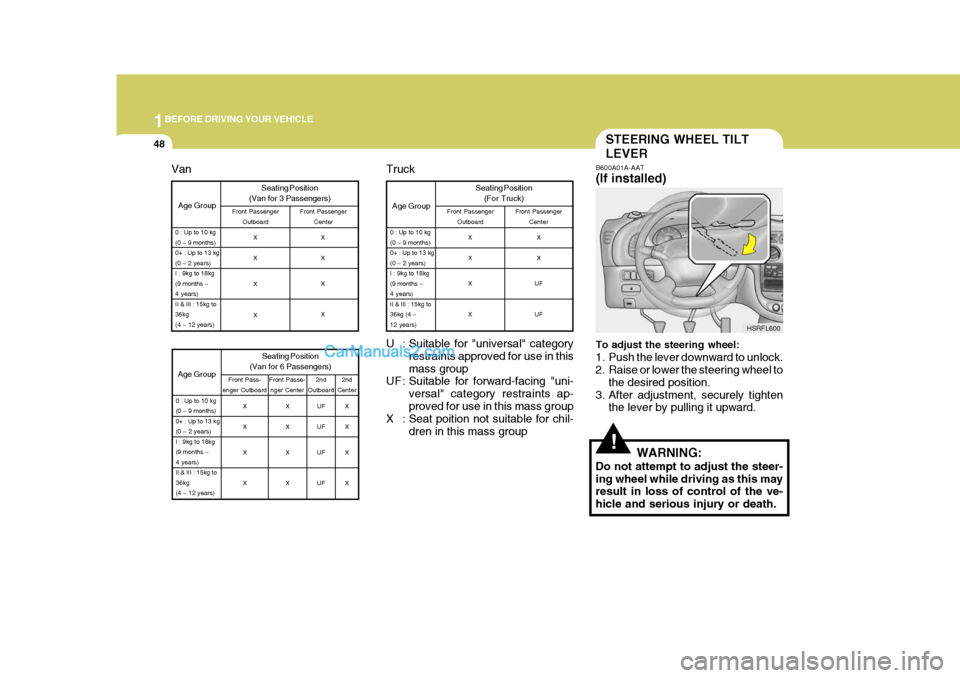
U : Suitable for "universal" category restraints approved for use in thismass group
UF : Suitable for forward-facing "uni-
versal" category restraints ap-proved for use in this mass group
X : Seat poition not suitable for chil-
dren in this mass group
Age Group
0 : Up to 10 kg (0 ~ 9 months)0+ : Up to 13 kg(0 ~ 2 years)I : 9kg to 18kg(9 months ~4 years)II & III : 15kg to36kg (4 ~12 years)
Truck Seating Position(For Truck)
Front Passenger Outboard Front Passenger
Center
X X X X X X
UF UF
Age Group Seating Position
(Van for 3 Passengers)Front Passenger Outboard Front Passenger
Center
0 : Up to 10 kg (0 ~ 9 months)0+ : Up to 13 kg(0 ~ 2 years)I : 9kg to 18kg(9 months ~4 years)II & III : 15kg to36kg(4 ~ 12 years)
X X X X X X X X
Age Group
0 : Up to 10 kg (0 ~ 9 months)0+ : Up to 13 kg(0 ~ 2 years)I : 9kg to 18kg(9 months ~4 years)II & III : 15kg to36kg(4 ~ 12 years)
Van
2nd
Center
2nd
Outboard
Seating Position
(Van for 6 Passengers)
Front Pass-
enger Outboard Front Passe-
nger Center
X X X X X X X XUF UF UF UFX X X X
Page 130 of 205

4
CORROSION PREVENTION AND APPEARANCE CARE
29
4
IN CASE OF EMERGENCY
29
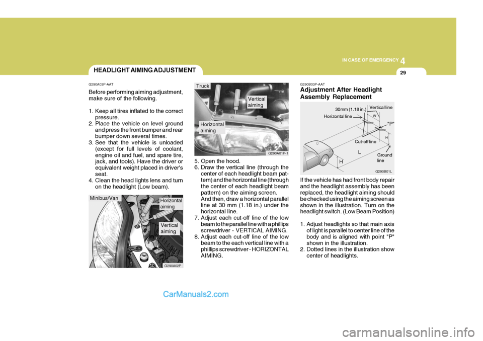
G290B03P-AAT Adjustment After Headlight Assembly Replacement If the vehicle has had front body repair and the headlight assembly has been replaced, the headlight aiming should be checked using the aiming screen asshown in the illustration. Turn on the headlight switch. (Low Beam Position)
1. Adjust headlights so that main axis
of light is parallel to center line of the body and is aligned with point "P"shown in the illustration.
2. Dotted lines in the illustration show
center of headlights.
5. Open the hood.
6. Draw the vertical line (through the
center of each headlight beam pat- tern) and the horizontal line (through the center of each headlight beam pattern) on the aiming screen.And then, draw a horizontal parallel line at 30 mm (1.18 in.) under the horizontal line.
7. Adjust each cut-off line of the low beam to the parallel line with a phillipsscrewdriver - VERTICAL AIMING.
8. Adjust each cut-off line of the low beam to the each vertical line with aphillips screwdriver - HORIZONTALAIMING.
Horizontal aiming
Verticalaiming
G290A01P-1
Truck
G290B01L
LW
H
H Cut-off line
Ground line
"P"
Horizontal line
30mm (1.18 in.) Vertical line
HEADLIGHT AIMING ADJUSTMENT
G290A03P-AAT Before performing aiming adjustment, make sure of the following.
1. Keep all tires inflated to the correct pressure.
2. Place the vehicle on level ground
and press the front bumper and rear bumper down several times.
3. See that the vehicle is unloaded
(except for full levels of coolant,engine oil and fuel, and spare tire, jack, and tools). Have the driver or equivalent weight placed in driver'sseat.
4. Clean the head lights lens and turn
on the headlight (Low beam).
Minibus/Van
G290A02P
Horizontal aiming
Verticalaiming
Page 202 of 205

10
INDEX
3
D
DAY/NIGHT INSIDE REARVIEW MI RROR .............2-34
DEFROSTING/DEFOGGING ...................................2-43
DIGITAL CLOCK ...................................................... 2-37
DOOR LOCKS .......................................................... 1-12
DRINK HOLDER ....................................................... 2-35
DRIVING FOR ECONOMY ......................................3-25
DRIVING WITH ELECTRONIC DUAL-RANGE AUTOMATIC TRANSM ISSION ............................. 3-13
EEMISSION CONTROL SYSTEM ............................... 7-2
ENGINE ...................................................................... 9-3
ENGINE COMPARTMENT ......................... ................ 8-2
ENGINE COOLANT .................................................. 8-10
ENGINE COOLANT TEM PERATURE GAUGE.......2-12
ENGINE NUMBER ..................................................... 1-5
ENGINE OI L ............................................................... 8-7
ENGINE RPM ADJUSTMENT KNOB ......................2-24
EXPLANATION OF SCHEDULED MAINTENANCE ITEMS .............. ...........................6-12
FFOUR-WHEEL DRIVE (4WD) ..................................3-15
FRONT DOOR EDGE WARNING LIGHT ...............2-25
FRONT DOOR WINDOW GLASS ...........................1-25
FRONT FOG LIGHT SWITCH .................................2-25FRONT/REAR WINDOW DEFROSTER
SWITCH .. 2-26
FUEL GAUGE ........................................................... 2-12
FUEL TANK CAPACITY ............................................. 9-2
FUSE PANEL DESCRIPTION ..................................4-40
GGENERAL CHECKS ................................................... 8-6
GOOD BRAKING PRACTICE ..................................3-22
HHAZARD WARNING SYSTEM................................ 2-26
HEADLIGHT AIMING ADJUSTMENT ......................4-29
HEADLIGHT LEVELING DEVICE SYSTEM ............2-23
HEADREST ............................................................... 1-37
HEATING AND COOLING CONTROL ....................2-38
HEATING CONTROLS ............................................. 2-42
HEIGHT ADJUSTABLE FRONT SEAT SHOULDER BELT ...................................................................... 1-41
HIGH-MOUNTED REAR STOP LIGHT ...................2-25
HOLD OPEN LOCK SYSTEM................................. 1-13
HOOD RELEASE ..................................................... 1-23
HORN ........................................................................ 2-37