Page 164 of 205

6
VEHICLE MAINTENANCE REQUIREMENTS
13
G080E01P-GAT
o Vacuum and Crankcase
Ventilation Hoses
Inspect the surface of hoses for evi- dence of heat and/or mechanical dam- age. Hard and brittle rubber, cracking, tears, cuts, abrasions, and excessiveswelling indicate deterioration. Particu- lar attention should be paid to examin- ing those hose surfaces nearest tohigh heat sources, such as the ex- haust manifold. Inspect the hose routing to assure that the hoses do not come in contact with any heat source, sharp edges or mov- ing component which might cause heatdamage or mechanical wear. Inspect all hose connections, such as clamps and couplings, to make sure they aresecure, and that no leaks are present. Hoses should be replaced immedi- ately if there is any evidence of dete-rioration or damage. G080F01P-GAT
o Fuel Hose, Vapor Hose and
Fuel Filler Cap
The fuel hose, vapor hose and fuelfiller cap should be inspected at those intervals specified in the maintenance schedule. Make sure that a new fuelhose, vapor hose or fuel filler cap is correctly replaced. Consult your Hyundai dealer if you have any ques-tions. G080G01P-GAT
o Air Cleaner Filter
A genuine Hyundai part is recom- mended for replacement of the air cleaner filter. G080H01P-GAT
o Spark Plugs (Gasoline) Make sure to install new spark plugs of the correct heat range. G080I01P-GAT
o Drive Belts Inspect all drive belts (water pump and alternator) for evidence of cuts, cracks, excessive wear or oiliness, and re- place if necessary. Drive belts shouldbe checked periodically for proper ten- sion and adjusted as necessary. G080J01P-GAT
o Engine Coolant The coolant should be changed at those intervals specified in the Vehicle Maintenance Requirements Section. G080K01P-GAT
o Timing Belt Inspect all parts related with the timing belt for damage and deformation. Re-place any damaged parts.
Page 169 of 205

7
EMISSION CONTROL SYSTEM
3CATALYTIC CONVERTER
H040A01P-GAT Canister While the engine is inoperative, fuel vapors generated inside the fuel tank are absorbed and stored in the canis-ter. When the engine is running, the fuel vapors absorbed in the canister are drawn into the induction systemthrough the purge control solenoid valve. H090A01P-GAT Purge Control Solenoid Valve The purge control solenoid valve is controlled by the ECU; when the en-gine coolant temperature is low, and during idling, it closes, so that evapo- rated fuel is not taken into the surgetank. After engine warm-up, during ordinary driving, it opens so as to introduce evaporated fuel to the surgetank. H050A01P-GAT
3. Exhaust Emission Control
System
The Exhaust Emission Control Sys-
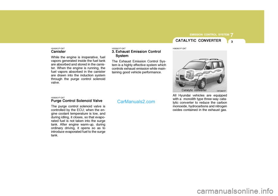
tem is a highly effective system which controls exhaust emission while main-taining good vehicle performance. H060A01P-GAT All Hyundai vehicles are equipped with a monolith type three-way cata- lytic converter to reduce the carbonmonoxide, hydrocarbons and nitrogen oxides contained in the exhaust gas.
H010A01P
Catalytic converter
Page 178 of 205

8
DO-IT YOURSELF MAINTENANCE
9
!
I060A01P-GAT
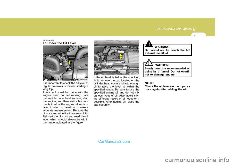
To Check the Oil Level
If the oil level is below the specified limit, remove the cap located on the cylinder head cover and add enoughoil to raise the level to within the specified range. Be sure to use the specified engine oil and do not mixvarious types of oil. Also, avoid mix- ing different makes of oil together if possible. After adding oil, close thecap securely.
It is important to check the oil level at
regular intervals or before starting a long trip.
This check must be made with the
engine warm but not running. Park the vehicle on a level surface, stopthe engine, and then wait a few mo- ments to allow the engine oil in circu- lation to return to the oil pan to ensureaccurate measurement. Remove the dipstick and wipe it with a clean cloth. Reinsert the dipstick and read the oillevel, which should always be within the range indicated in the figure. WARNING:
Be careful not to touch the hot exhaust manifold.
CAUTION:
Slowly pour the recommended oilusing by a funnel. Do not overfillnot to damage engine. NOTE: Check the oil level on the dipstick once again after adding the oil.
!
I060A01P I060B02P
Page 181 of 205

8DO-IT YOURSELF MAINTENANCE
12
!
4. Turn the radiator cap counterclock-
wise without pressing down on it, until it stops. This relieves any pres- sure remaining in the cooling sys- tem. And remove the radiator capby pushing down and turning coun- terclockwise. Now fill the radiator with clean dem- ineralized or distilled water. Con- tinue to add clean demineralized or distilled water in small quantitiesuntil the fluid level stays up in the radiator neck.
5. Start the engine, top off the radia- tor with water and then add engine coolant to the reservoir until thelevel is between "L" and "F".
6. Replace the radiator and reservoir caps and check to be sure thedrain cocks are fully closed and not leaking. WARNING:
The cooling fan is controlled by
engine coolant temperature andmay sometimes operate even when the engine is not running. Useextreme caution when working near the blades of the cooling fan so that you are not injured by a rotat-ing fan blade. As the engine cool- ant temperature decreases, the fan will automatically shut off. This isa normal condition.
G050D02P-AAT To Change the Coolant The coolant should be changed at those intervals specified in the ve- hicle maintenance schedule in Sec- tion 6.
!
CAUTION:
Engine coolant can damage the finish of your car. If you spill en-gine coolant on the car, wash it off thoroughly with clean water.
1. Park the car on level ground, set the parking brake and remove the radiator cap when cool.
2. Be sure your drain receptacle is in
place. Open the drain cock on theradiator. Allow all the engine cool- ant to drain from the cooling sys- tem, then securely close the draincock.
3. Check Section 9 for the capacity of the cooling system in your car.Then, following the manufacturer's directions on the engine coolant container, add the appropriatequantity of coolant to the radiator.
Page 188 of 205

8
DO-IT YOURSELF MAINTENANCE
19
!WARNING:
The cooling fan is controlled by
engine coolant temperature and may sometimes operate even whenthe engine is not running. Use extreme caution when working near the blades of the cooling fan, sothat you are not injured by a rotat- ing fan blade. As the engine cool- ant temperature decreases, the fanwill automatically shut off. This is a normal condition.
FILLING THE WASHER RESERVOIR
I130A01P-GAT The washer fluid reservoir supplies
fluid to the windshield washer sys- tem.
A good quality washer fluid should be
used to fill the washer reservoir. Thefluid level should be checked more frequently during bad weather or whenever the washer system is inmore frequent use.
!WARNING (Diesel only):
Never work on injection system with engine running or within 30 seconds after shutting off engine.High pressure pump, rail, injec- tors and high pressure pipes are subject to high pressure even af-ter the engine stopped. The fuel jet produced by fuel leaks may cause serious injury, if it touch the body.People using pacemakers should not move than 30cm closer to the ECU or wiring harness within theengine room while engine is run- ning, since the high currents in the Common Rail system produceconsiderable magnetic fields. I130A01P