Page 60 of 205

1BEFORE DRIVING YOUR VEHICLE
46
B230G01P-GAT Installation on Outboard Rear Seats To install a child restraint system in the outboard rear seats, extend the shoul- der/lap belt from its retractor. Install the child restraint system, buckle theseat belt and allow the seat belt to take up any slack. Make sure that the lap portion of the belt is tight around thechild restraint system and the shoulder portion of the belt is positioned so that it cannot interfere with the child's heador neck. After installation of the child restraint system, try to move it in all directions to be sure the child restraintsystem is securely installed. B230G01L-1
To install a child restraint system in thecenter rear seat, extend the shoulder/lap belt entirely from its retractor until a "click" is felt. This will engage the seat belt retractor automatic lockingfeature, which allows the seat belt to retract but not extend. Install the child restraint system, buckle the seat beltand allow the seat belt to take up any slack. Make sure that the lap portion of the belt is tight around the child re-straint system and the shoulder por- tion of the belt is positioned so that it can not interfere with the child's heador neck. Also, double check to be sure that the retractor has engaged the Automatic Locking feature by trying toextend webbing out of the retractor. If the retractor is in the Automatic Lock- ing mode, the belt will be locked.B230F02P-AAT Installation on Rear Seat Center Position
2 point static type
B235G02Y
B235G01Y-1
3 point type
Page 62 of 205

1BEFORE DRIVING YOUR VEHICLE
48STEERING WHEEL TILT LEVER
!
B600A01A-AAT (If installed) To adjust the steering wheel:
1. Push the lever downward to unlock.
2. Raise or lower the steering wheel to the desired position.
3. After adjustment, securely tighten the lever by pulling it upward.
WARNING:
Do not attempt to adjust the steer- ing wheel while driving as this may result in loss of control of the ve- hicle and serious injury or death. HSRFL600
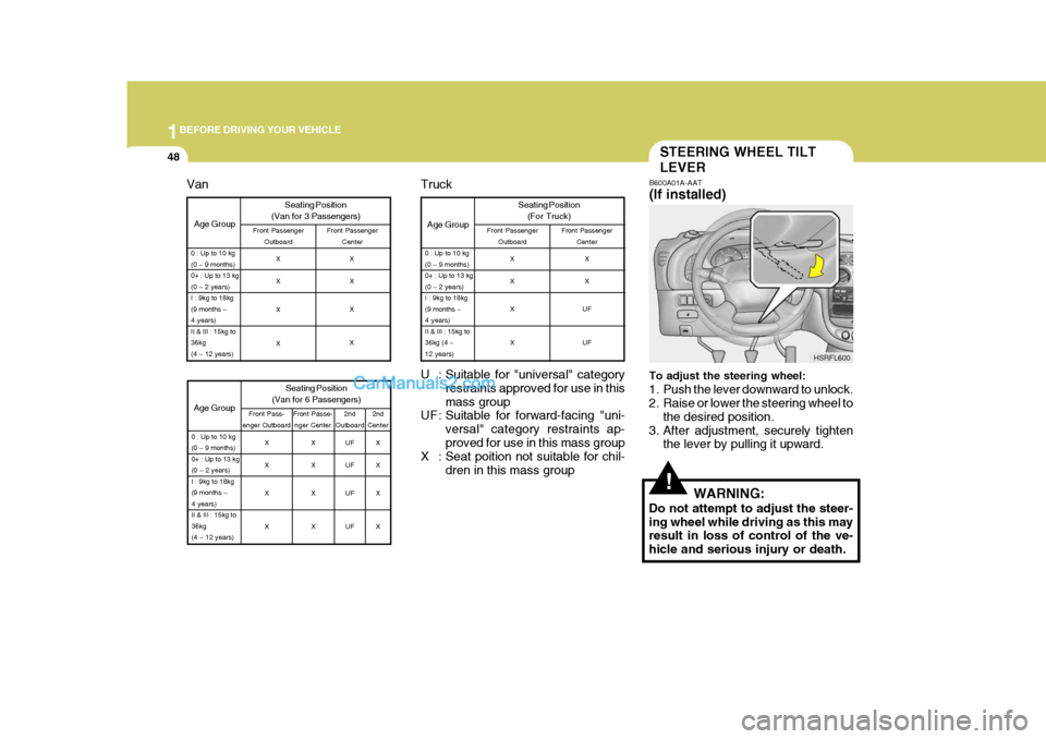
U : Suitable for "universal" category restraints approved for use in thismass group
UF : Suitable for forward-facing "uni-
versal" category restraints ap-proved for use in this mass group
X : Seat poition not suitable for chil-
dren in this mass group
Age Group
0 : Up to 10 kg (0 ~ 9 months)0+ : Up to 13 kg(0 ~ 2 years)I : 9kg to 18kg(9 months ~4 years)II & III : 15kg to36kg (4 ~12 years)
Truck Seating Position(For Truck)
Front Passenger Outboard Front Passenger
Center
X X X X X X
UF UF
Age Group Seating Position
(Van for 3 Passengers)Front Passenger Outboard Front Passenger
Center
0 : Up to 10 kg (0 ~ 9 months)0+ : Up to 13 kg(0 ~ 2 years)I : 9kg to 18kg(9 months ~4 years)II & III : 15kg to36kg(4 ~ 12 years)
X X X X X X X X
Age Group
0 : Up to 10 kg (0 ~ 9 months)0+ : Up to 13 kg(0 ~ 2 years)I : 9kg to 18kg(9 months ~4 years)II & III : 15kg to36kg(4 ~ 12 years)
Van
2nd
Center
2nd
Outboard
Seating Position
(Van for 6 Passengers)
Front Pass-
enger Outboard Front Passe-
nger Center
X X X X X X X XUF UF UF UFX X X X
Page 103 of 205
44IN CASE OF EMERGENCY
2
Release valve
TOOLS AND JACK
E010A01P-GAT To provide for cases of emergency, always remember where the tools and jack are stowed and how the jack is removed for use.
E010B03P-GAT Storage places E010C03P-GAT TOOLS
E020A01P-GATJACK To use the jack
The tool box is at the right rear corner of the luggage compartment (minibus/ van) or on the floor behind the seat(truck). Minibus/Van Truck
1. Tool case
2. Wheel nut wrench
3. Screwdriver
4. Spare wheel carrier wrench(Truck only) 4
Turn the knob clockwise, and then remove the lid. Remove the securing nut, and then take out the jack.
E010B01P-2 E010C03P
E020A01P
Minibus/Van Truck
Securing nut
Ram 1
2 3
Page 105 of 205
44IN CASE OF EMERGENCY
4
E050B02P-GAT To reinstall the spare tire Installation is the reverse order of dis- assembly.
CAUTION:
The spare tire should always besecurely in position.If a flat tire is changed, put the flat tire in the spare tire mounting posi- tion, and use the wheel nut wrenchto secure it firmly.
!
To remove the spare tire:
1. Open the tailgate
2. Remove the plastic cover.
HSRFL052
HSRFL053
3. Use the wheel nut wrench to loosen the holder mounting bolt. HSRFL054
HSRFL055
4. Lift up the hanger and separate it from the holder, and then lower the hanger and remove the spare tire.
Page 107 of 205

44IN CASE OF EMERGENCY
6IF YOU HAVE A FLAT TIRE
7. After the spare tire fully raised, tighten by hand to about 30 kg .
f
(295 N). Then, remove the spare tire carrier wrench with care not to turn it in thereverse direction. Now, ensure that the tire is secured in position.
CAUTION:
If you cannot secure the spare tire in position, load it on the cargodeck and ask your nearest service shop for inspection.
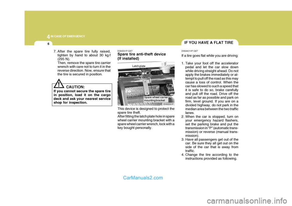
! E050D01P-GAT Spare tire anti-theft device (If installed) This device is designed to protect the spare tire theft. After fitting the latch plate hole in spare wheel carrier mounting bracket with aspare wheel carrier wrench, lock with a key bought personally.Latch plate
E050D01PD050A01HP-GAT If a tire goes flat while you are driving:
1. Take your foot off the accelerator
pedal and let the car slow down while driving straight ahead. Do not apply the brakes immediately or at- tempt to pull off the road as this maycause a loss of control. When the car has slowed to such a speed that it is safe to do so, brake carefullyand pull off the road. Drive off the road as far as possible and park on firm, level ground. If you are on adivided highway, do not park in the median area between the two traffic lanes.
2. When the car is stopped, turn on your emergency hazard flashers,set the parking brake and put thetransmission in "P" (automatic trans- mission) or reverse (manual trans- mission).
3. Have all passengers get out of the car. Be sure they all get out on theside of the car that is away fromtraffic.
4. Change the tire according to the
instructions provided as following.
Spare wheel carrier mounting bracket
Page 110 of 205

4
CORROSION PREVENTION AND APPEARANCE CARE
9
4
IN CASE OF EMERGENCY
9
D060F02P-GAT 5. Raising the Car Open the lid at the right corner of the luggage compartment (minibus/van)or on the floor behind the seat (truck). Loosen the securing nut, and then take out the jack. Using the jack handle, turn the releasevalve clockwise until it reaches a stop.
HAUT408
HAUT405
E020A01P
Move the jack handle up and down to raise the ram until just before the jack contacts the jacking point of the car.Position the jack with the jack handle. Position it only at the specified points indicated in the "Put the Jack in Place".Use of the jack at other points could damage the car. Moving the jack handle up and down toraise the ram. As the jack begins to raise the vehicle, double check that it is properly posi-tioned and will not slip.
Then fit the jack handle into the holder,and align the groove of the jack handle with the notch of the holder.
Minibus/Van Truck
HAUT406RamPressure piston
Jack handle
Notch of holder
Page 113 of 205

44IN CASE OF EMERGENCY
12
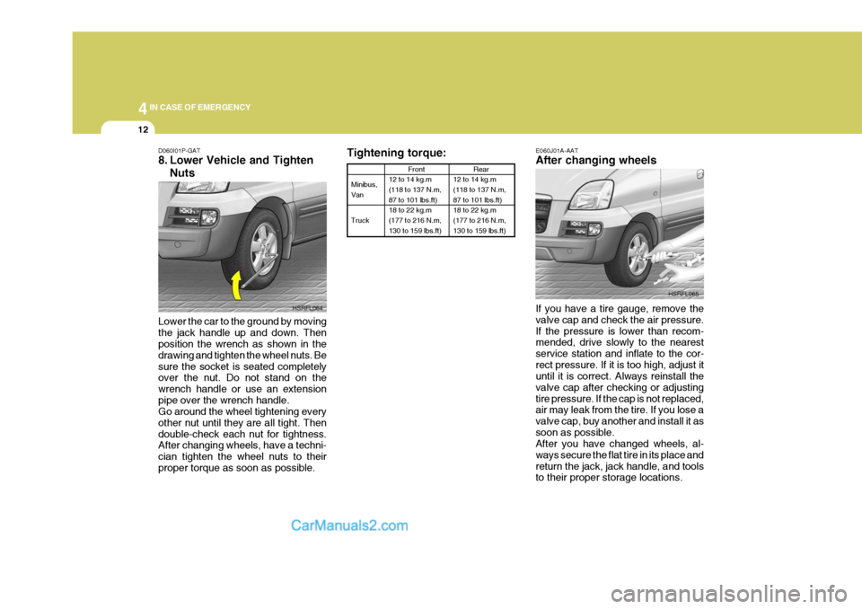
Tightening torque:
Minibus, Van Truck Front
12 to 14 kg.m (118 to 137 N.m, 87 to 101 lbs.ft) 18 to 22 kg.m(177 to 216 N.m, 130 to 159 lbs.ft)
Rear
12 to 14 kg.m (118 to 137 N.m, 87 to 101 lbs.ft) 18 to 22 kg.m(177 to 216 N.m, 130 to 159 lbs.ft)
E060J01A-AAT After changing wheels If you have a tire gauge, remove the valve cap and check the air pressure.If the pressure is lower than recom- mended, drive slowly to the nearest service station and inflate to the cor-rect pressure. If it is too high, adjust it until it is correct. Always reinstall the valve cap after checking or adjustingtire pressure. If the cap is not replaced, air may leak from the tire. If you lose a valve cap, buy another and install it assoon as possible. After you have changed wheels, al- ways secure the flat tire in its place andreturn the jack, jack handle, and tools to their proper storage locations. HSRFL065
D060I01P-GAT
8. Lower Vehicle and Tighten
Nuts
Lower the car to the ground by moving the jack handle up and down. Then position the wrench as shown in the drawing and tighten the wheel nuts. Besure the socket is seated completely over the nut. Do not stand on the wrench handle or use an extensionpipe over the wrench handle. Go around the wheel tightening every other nut until they are all tight. Thendouble-check each nut for tightness. After changing wheels, have a techni- cian tighten the wheel nuts to theirproper torque as soon as possible. HSRFL064
Page 118 of 205

4
CORROSION PREVENTION AND APPEARANCE CARE
17
4
IN CASE OF EMERGENCY
17
C190B01S-AAT Trailer Hitches Select the proper hitch and ball combi- nation, making sure that its location iscompatible with that of the trailer or vehicle being towed. Use a quality non-equalizing hitch which distributesthe tongue load uniformly throughout the chassis. The hitch should be bolted securely to the car and installed by a qualified technician. DO NOT USE A HITCHDESIGNED FOR TEMPORARY IN- STALLATION AND NEVER USE ONE THAT ATTACHES ONLY TO THEBUMPER. C190C01P-GAT Trailer Brakes If your trailer is equipped with a braking system, make sure it conforms to fed-eral and/or local regulations and that it is properly installed and operating cor- rectly. NOTE: If you tow a trailer or vehicle, your car will require more frequent main-tenance due to the additional load. See "Maintenance Under Severe Usage Conditions" on page 6-11.
CAUTION:
o Never connect a trailer brake sys- tem directly to the vehicle brakesystem.
o When towing a trailer on steep
grades (in excess of 12%) payclose attention to the engine cool- ant temperature gauge to ensure the engine does not overheat. Ifthe needle of the coolant tem- perature gauge moves across the dial towards "H" (HOT), pull over
!
C190A01A-GAT TRAILER OR VEHICLE TOWING If you are considering towing with your car, you should first check with yourProvince Department of Motor Vehicles to determine their legal requirements. Since laws vary from province to prov-ince, the requirements for towing trail- ers, cars, other types of vehicles, or apparatus may differ. Ask your Hyundaidealer for further details before towing.
CAUTION:
Do not do any towing with your carduring its first 2,000 km (1,200 miles)in order to allow the engine to prop- erly break in. Failure to heed this caution may result in serious en-gine or transmission damage.
!