Page 231 of 297

5VEHICLE MAINTENANCE REQUIREMENTS
4
Note : (1) For every 40,000 km : "R" (2) For every 160,000 km : "R" (3) For every 96,000 km or 48 months, whichever occurs first : "I"(4) For every 20,000 km : "I"
NO.
1234 5 6789
10111213 ENGINE CONTROL SYSTEM MAINTENANCEENGINE OIL & FILTERDRIVE BELT (AUTO-TENSIONER, ALTERNATOR, P/STR'G, W/PUMP)FUEL FILTER (MPI TYPE)FUEL LINES, FUEL HOSES & CONNECTIONSVAPOR HOSE & FUEL FILLER CAP VACUUM HOSE CRANKCASE VENTILATION HOSEAIR CLEANER FILTERSPARK PLUGS (Leaded)SPARK PLUGS (Unleaded-IRIDIUM COATED)VALVE CLEARANCE FUEL TANK AIR FILTER ELECTRONIC THROTTLE CONTROL
F030A01A-GAT The following maintenance services must be performed to assure good vehicle control and performance. Keep receipts for all vehicle services to protect your warranty. Where both mileage and time are shown, the frequency of service is determinedby whichever occurs first. F030B01TG-GAT R :Replace I : Inspect and, after Inspection, clean, adjust, repair or replace if necessary.
SCHEDULED MAINTENANCE
120
96
R I
R
I II
R
I
105
84
R
I I I I I
90 72
R I I III
R R
75 60
R
I I I I I
60 48
R I
R
III
R
I
4536
R
IIII I
R
30 24
R I I II
R
I
1512
R
III I IKILOMETERS X 1000 MONTHSDESCRIPTION
See Note (1) See Note (2) See Note (3) See Note (4)
Page 234 of 297

5
VEHICLE MAINTENANCE REQUIREMENTS
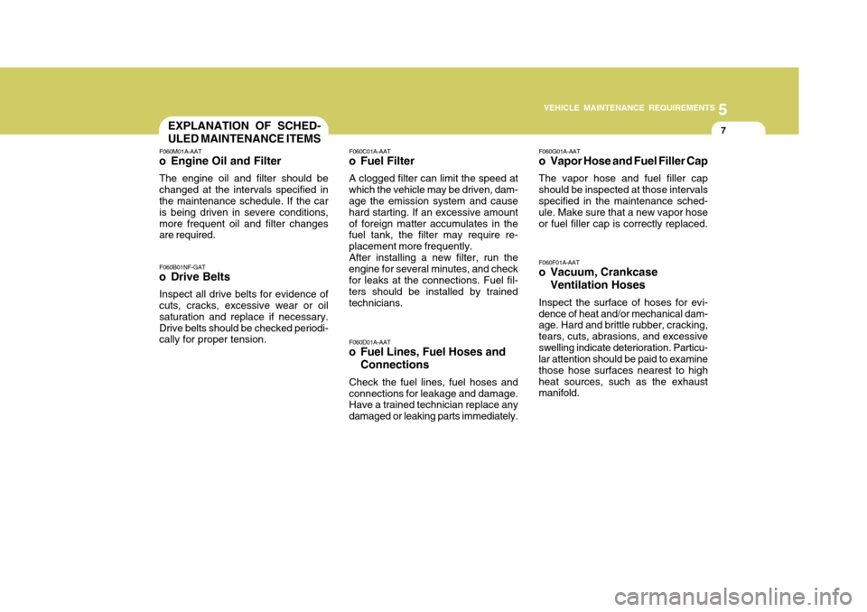
7EXPLANATION OF SCHED- ULED MAINTENANCE ITEMS
F060M01A-AAT
o Engine Oil and Filter
The engine oil and filter should be changed at the intervals specified in the maintenance schedule. If the car is being driven in severe conditions,more frequent oil and filter changes are required. F060B01NF-GAT
o Drive Belts
Inspect all drive belts for evidence of cuts, cracks, excessive wear or oil saturation and replace if necessary.Drive belts should be checked periodi- cally for proper tension. F060C01A-AAT
o Fuel Filter
A clogged filter can limit the speed at
which the vehicle may be driven, dam-age the emission system and cause hard starting. If an excessive amountof foreign matter accumulates in the fuel tank, the filter may require re- placement more frequently. After installing a new filter, run the
engine for several minutes, and checkfor leaks at the connections. Fuel fil- ters should be installed by trained technicians.
F060D01A-AAT
o Fuel Lines, Fuel Hoses and
Connections
Check the fuel lines, fuel hoses and
connections for leakage and damage. Have a trained technician replace any damaged or leaking parts immediately. F060G01A-AAT
o Vapor Hose and Fuel Filler Cap The vapor hose and fuel filler cap should be inspected at those intervals specified in the maintenance sched- ule. Make sure that a new vapor hoseor fuel filler cap is correctly replaced. F060F01A-AAT
o Vacuum, Crankcase
Ventilation Hoses
Inspect the surface of hoses for evi- dence of heat and/or mechanical dam- age. Hard and brittle rubber, cracking, tears, cuts, abrasions, and excessiveswelling indicate deterioration. Particu- lar attention should be paid to examine those hose surfaces nearest to highheat sources, such as the exhaust manifold.
Page 279 of 297

7EMISSION CONTROL SYSTEMS
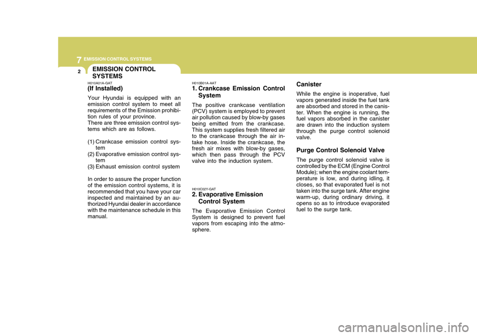
2EMISSION CONTROL SYSTEMS
H010A01A-GAT
(If Installed)
Your Hyundai is equipped with an
emission control system to meet all requirements of the Emission prohibi- tion rules of your province.
There are three emission control sys-
tems which are as follows.
(1) Crankcase emission control sys- tem
(2) Evaporative emission control sys- tem
(3) Exhaust emission control system
In order to assure the proper function
of the emission control systems, it is recommended that you have your carinspected and maintained by an au- thorized Hyundai dealer in accordance with the maintenance schedule in thismanual. H010B01A-AAT
1. Crankcase Emission Control
System
The positive crankcase ventilation
(PCV) system is employed to preventair pollution caused by blow-by gasesbeing emitted from the crankcase. This system supplies fresh filtered air to the crankcase through the air in-take hose. Inside the crankcase, the fresh air mixes with blow-by gases, which then pass through the PCVvalve into the induction system.
H010C02Y-GAT
2. Evaporative Emission
Control System
The Evaporative Emission Control
System is designed to prevent fuelvapors from escaping into the atmo-sphere. Canister
While the engine is inoperative, fuel
vapors generated inside the fuel tankare absorbed and stored in the canis-ter. When the engine is running, the fuel vapors absorbed in the canister are drawn into the induction systemthrough the purge control solenoid valve. Purge Control Solenoid Valve
The purge control solenoid valve is
controlled by the ECM (Engine Control Module); when the engine coolant tem- perature is low, and during idling, it closes, so that evaporated fuel is not taken into the surge tank. After enginewarm-up, during ordinary driving, it opens so as to introduce evaporated fuel to the surge tank.