2005 Hyundai Azera check engine
[x] Cancel search: check enginePage 254 of 297

6 DO-IT-YOURSELF MAINTENANCE
18
G140C01A-AAT
Lubrication
To lubricate the compressor and the
seals in the system, the air condition- ing should be run for at least 10 minutes each week. This is particu-larly important during cool weather when the air conditioning system is not otherwise in use.CHANGING THE AIR CONDITIONER FILTER
B145A01TG-GAT
(For Evaporator and Blower Unit)(If Installed)
The air conditioner filter is located in
the upper portion of the blower fan. It helps to decrease the amount of
pollutants entering the car.
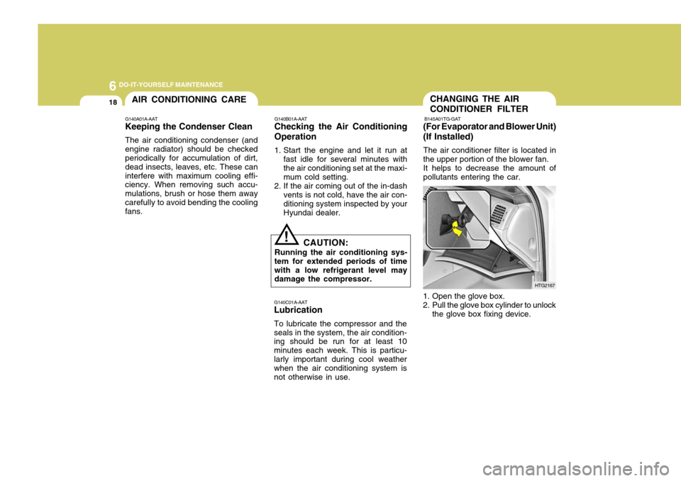
1. Open the glove box.
2. Pull the glove box cylinder to unlock the glove box fixing device. HTG2167
G140B01A-AAT
Checking the Air Conditioning Operation
1. Start the engine and let it run at
fast idle for several minutes with the air conditioning set at the maxi- mum cold setting.
2. If the air coming out of the in-dash vents is not cold, have the air con-ditioning system inspected by yourHyundai dealer.
CAUTION:
Running the air conditioning sys-
tem for extended periods of timewith a low refrigerant level may damage the compressor.
!
AIR CONDITIONING CARE
G140A01A-AAT Keeping the Condenser Clean The air conditioning condenser (and engine radiator) should be checked periodically for accumulation of dirt, dead insects, leaves, etc. These caninterfere with maximum cooling effi- ciency. When removing such accu- mulations, brush or hose them awaycarefully to avoid bending the cooling fans.
Page 256 of 297

6 DO-IT-YOURSELF MAINTENANCE
20
G180A01L
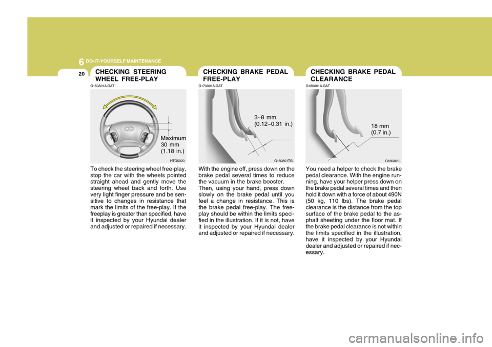
18 mm (0.7 in.)
You need a helper to check the brake
pedal clearance. With the engine run- ning, have your helper press down on the brake pedal several times and thenhold it down with a force of about 490N (50 kg, 110 lbs). The brake pedal clearance is the distance from the topsurface of the brake pedal to the as- phalt sheeting under the floor mat. If the brake pedal clearance is not withinthe limits specified in the illustration, have it inspected by your Hyundai dealer and adjusted or repaired if nec-essary.
With the engine off, press down on the
brake pedal several times to reduce the vacuum in the brake booster.
Then, using your hand, press down
slowly on the brake pedal until you feel a change in resistance. This isthe brake pedal free-play. The free- play should be within the limits speci- fied in the illustration. If it is not, haveit inspected by your Hyundai dealer and adjusted or repaired if necessary. G160A01TG
3~8 mm (0.12~0.31 in.)To check the steering wheel free-play, stop the car with the wheels pointed straight ahead and gently move the steering wheel back and forth. Usevery light finger pressure and be sen- sitive to changes in resistance that mark the limits of the free-play. If thefreeplay is greater than specified, have it inspected by your Hyundai dealer and adjusted or repaired if necessary. HTG5020
Maximum 30 mm (1.18 in.)
CHECKING STEERING WHEEL FREE-PLAY
G150A01A-GATCHECKING BRAKE PEDAL FREE-PLAY
G170A01A-GATCHECKING BRAKE PEDAL CLEARANCE
G180A01A-GAT
Page 257 of 297

6
DO-IT-YOURSELF MAINTENANCE
21
G190A02NF-GAT
Drive belts should be checked periodi-
cally for proper tension. At the same time, belts should be examined forcracks, wear, fraying or other evidence of deterioration and replaced if neces- sary.
When a new belt is replaced, the belt
should be located within the pulley offlat idler. Belt routing should also be checked
to be sure there is no interferencebetween the belts and other parts of the engine.
NOTE: Drive belt tension is adjusted auto-
matically by the auto tensioner. CHECKING DRIVE BELTS
G140D02NF
Power steeringCOMP
Water pump pully
Generator
Damper pulley
Auto tensioner
CHECKING AND REPLAC- ING FUSES
G200A01A-GAT
Replacing a Fusible Link
A fusible link will melt if the electrical circuits from the battery are ever over- loaded, thus preventing damage to the entire wiring harness. (This couldbe caused by a short in the system drawing too much current.) If this ever happens, have a Hyundai dealerdetermine the cause, repair the sys- tem and replace the fusible link. The fusible links are located in a relay boxfor easy inspection. HNF4004
The parking brake pedal should bechecked periodically for proper stroke.If you feel loose in the parking brake pedal when the parking brake is en- gaged, have your parking brake ad-justed by an authorized Hyundai dealer.CHECKING PARKING BRAKE PEDAL
G185A01TG-GAT
CAUTION:
If the parking brake pedal is not adjusted properly, the vehicle may roll backwards when parking on a steep hill.
!
Page 258 of 297

6 DO-IT-YOURSELF MAINTENANCE
22
1. Turn off the ignition and all other
switches.
2. Open the fuse box and examine each fuse. Remove each fuse by pulling it toward you (a small "fusepuller" tool is contained in the relay and fuse box of the engine room to simplify this operation).
G200B02NF
3. Be sure to check all other fuses even if you find one that appears tohave burned out.G200B01NF-GAT Replacing Accessory Fuse
G200B01TG
The fuse box for the lights and other electrical accessories will be found in the left side of the crash pad. Insidethe box you will find a list showing the circuits protected by each fuse. If any of your car's lights or other electrical accessories stop working, a blown fuse could be the reason. If the fuse has burned out, you will see thatthe metal strip inside the fuse has burned through. If you suspect a blown fuse, follow this procedure:
CAUTION:
When replacing a fusible link, never
use anything but a new fusible link with the same or lower amper- age rating. Never use a piece ofwire or a higher-rated fusible link. This could result in serious dam- age and create a fire hazard.
!
Page 261 of 297

6
DO-IT-YOURSELF MAINTENANCE
25
!
CHECKING ELECTRIC COOLING FANS
G220A01A-AAT
WARNING:
The cooling fan is controlled by
engine coolant temperature and may sometimes operate even whenthe engine is not running. Use extreme caution when working near the blades of the cooling fan, sothat you are not injured by a rotat- ing fan blade. As the engine cool- ant temperature decreases the fanwill automatically shut off. This is a normal condition.
G220B01NF-GAT
Checking Engine Cooling Fan
The engine cooling fan should come on automatically if the engine coolant temperature is high or whenever the air conditioning is in operation.POWER STEERING FLUID LEVEL
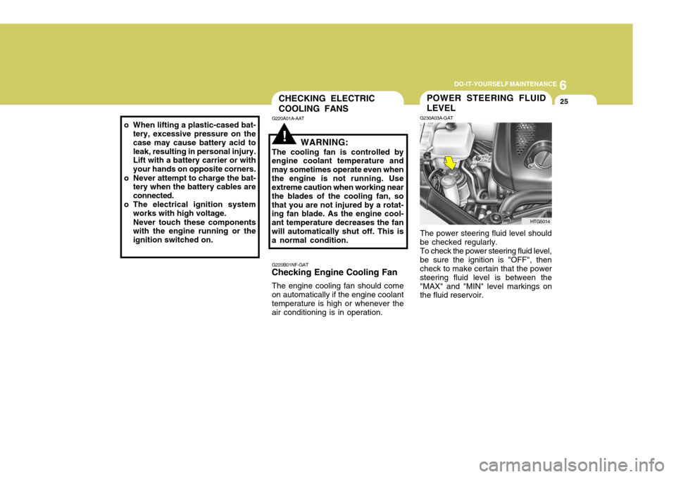
G230A03A-GAT The power steering fluid level should be checked regularly.To check the power steering fluid level,be sure the ignition is "OFF", then check to make certain that the power steering fluid level is between the"MAX" and "MIN" level markings on the fluid reservoir.
HTG5014
o When lifting a plastic-cased bat-
tery, excessive pressure on the case may cause battery acid toleak, resulting in personal injury. Lift with a battery carrier or with your hands on opposite corners.
o Never attempt to charge the bat- tery when the battery cables areconnected.
o The electrical ignition system works with high voltage. Never touch these components with the engine running or the ignition switched on.
Page 262 of 297

6 DO-IT-YOURSELF MAINTENANCE
26HEADLIGHT AIMING ADJUSTMENT
G290A01TG-GAT
G290A01NF
Before performing aiming adjustment, make sure of the following.
1. Keep all tires inflated to the correct pressure.
2. Place the vehicle on level ground and press the front bumper & rear bumper down several times. Place vehicle at a distance of 3m (118 in.) from the test wall.
3. See that the vehicle is unloaded (except for full levels of coolant,engine oil and fuel, and spare tire,jack, and tools). Have the driver or equivalent weight placed in driver's seat.
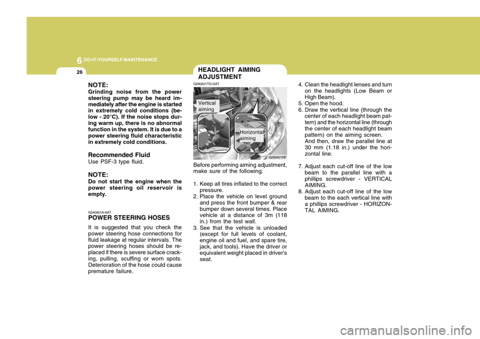
Vertical aiming
Horizontal aiming 4. Clean the headlight lenses and turn
on the headlights (Low Beam or High Beam).
5. Open the hood.
6. Draw the vertical line (through the center of each headlight beam pat- tern) and the horizontal line (throughthe center of each headlight beam pattern) on the aiming screen. And then, draw the parallel line at 30 mm (1.18 in.) under the hori- zontal line.
7. Adjust each cut-off line of the low beam to the parallel line with a phillips screwdriver - VERTICAL AIMING.
8. Adjust each cut-off line of the low beam to the each vertical line with a phillips screwdriver - HORIZON-TAL AIMING.
NOTE: Grinding noise from the power steering pump may be heard im-mediately after the engine is started in extremely cold conditions (be- low - 20°C). If the noise stops dur-ing warm up, there is no abnormal function in the system. It is due to a power steering fluid characteristicin extremely cold conditions.
Recommended Fluid Use PSF-3 type fluid. NOTE: Do not start the engine when the power steering oil reservoir is empty. G240A01A-AAT POWER STEERING HOSES It is suggested that you check the power steering hose connections forfluid leakage at regular intervals. The power steering hoses should be re- placed if there is severe surface crack-ing, pulling, scuffing or worn spots. Deterioration of the hose could cause premature failure.
Page 264 of 297

6 DO-IT-YOURSELF MAINTENANCE
28
Replacement instructions:
1. Allow the bulb to cool. Wear eye protection.
2. Open the engine hood and discon- nect the negative (-) post of the battery.
3. Always grasp the bulb by its plastic base, avoid touching the glass.
G270A01TG-GAT
HEADLIGHT AND FRONT FOG LIGHT
Headlight (High beam) Headlight(Low beam)
G270A01TG
Front Fog Light
REPLACEMENT OF LIGHT BULBS
G260A01TG-GAT Before attempting to replace a light
bulb, be sure the ignition switch is turned to the "OFF" position.
The next paragraph shows how to
reach the light bulbs so they may bechanged. Be sure to replace theburned-out bulb with one of the same number and wattage rating.
See page 6-36 for the wattage descrip-
tions.
! CAUTION:
o Keep the lights out of contact with petroleum products, such as oil, gasoline, etc.
o Be sure to replace the LED type
equipped bulbs with an assem- bly.
o If you don't have necessary tools, the correct bulbs and the exper-tise, consult your authorized Hyundai dealer. CAUTION:
o The headlight aiming should be checked by an authorized Hyundaidealer after replacing the head-light bulbs.
o If your vehicle is equipped with
HID (High Intensity Discharge) type headlight, you must not replace or inspect the headlight. It has a danger of an electric shock. If the headlight is not work- ing, have your vehicle inspectedby your Hyundai Dealer.
! Headlight
Page 274 of 297

6 DO-IT-YOURSELF MAINTENANCE
38
1 2 3 4 5 6 7 8 9 10 11 12 13 14 15 16 17 18 19 20 21 22 23 24
HORNTAIL
ECU IG1
DRL
FR FOG
A/CON
F/PUMP
DIODE ATM
STOP
H/LP LO RH
S/ROOF
H/LP WASHER
H/LP HI
ECU (B+)
SNSR3 SNSR1 SNSR2B/UP
IGN COIL
ECU (IG1)
H/LP LO ABS PROTECTED COMPONENTS
ABS/ESP Control module, Multipurpose check connectorABS/ESP Control module, Multipurpose check connector Fuse(FR P/SEAT, T/LID, T/SIG, TILT, PEDAL, RR CURTAIN) Defogger relay Blower relay Fuse(P/WDW LH, P/WDW RH) Start relay, Ignition switch(IG2, START) Engine control unit relay Fuse(KEY SOL, ECS/RR FOG), Power connector Ignition switch(ACC, IG1) Fusible link(ABS1, ABS2, RR HTD, BLOWER) Horn relay Tail light relay PCM (Spare) Burglar alarm horn relay Front fog light relay A/C Relay Fuel pump relay (Spare) ATM Control relay Stop light switch HID Relay Overhead console lamp Headlight washer motor Headlight relay (HIGH) PCM Injector#1~#6, A/C Relay, Cooling fan relay Mass air flow sensor, PCM, Immobilizer control module, Oil control valve#1/#2, Variable intake manifold valve Oxygen Sensor#1~#4 Back-up light switch, Stop light switch, Transaxle range switch, Vehicle speed sensor Ignition coil#1~#6, Condenser PCM Headlight relay(LOW) ABS/ESP Control module, Multipurpose check connector
ABS1 ABS2
I/P (B+)1
RR HTD
BLOWER
P/WDW IGN2
ECU RLY I/P (B+)2
IGN1ALT FUSE RATING
40A20A 40A 40A 40A 40A 40A 30A 30A 30A
150A
15A 20A 10A 10A 15A 15A 10A 20A
-
20A 15A 15A 15A 20A 20A 10A 10A 15A 15A 10A 20A 10A 20A 10ADESCRIPTION
FUSIBLE LINK
FUSE