2005 Hyundai Azera lights
[x] Cancel search: lightsPage 239 of 297

6
DO-IT-YOURSELF MAINTENANCE
3GENERAL CHECKS
G020A01NF-GAT
Engine Compartment
The following should be checked regu- larly:
o Engine oil level and condition
o Transaxle fluid level and condition
o Brake fluid level
o Engine coolant level
o Windshield washer fluid level
o Accessory drive belt condition
o Engine coolant hose condition
o Fluid leaks (on or below compo- nents)
o Power steering fluid level
o Battery condition
o Air filter condition
o Immediate repairing when engine trembling occurs
o Limit to restart more than 3 times when engine cannot start o Defroster, heating system operation
(and air conditioning, If Installed)
o Steering operation and condition
o Mirror condition and operation
o Turn signal operation
o Accelerator pedal operation
o Brake operation, including parking brake
o Automatic transaxle operation, in- cluding "Park" mechanism opera- tion
o Seat control condition and opera- tion
o Seat belt condition and operation
o Sun visor operation If you notice anything that does not operate correctly or appears to befunctioning incorrectly, inspect it care- fully and seek assistance from your Hyundai dealer if service is needed.
G020B01A-AAT
Vehicle Exterior
The following should be checked
monthly:
o Overall appearance and condition
o Wheel condition and wheel nut
torque
o Exhaust system condition
o Light condition and operation
o Windshield glass condition
o Wiper blade condition
o Paint condition and body corrosion
o Fluid leaks
o Door and hood lock condition
o Tire pressure and condition (including spare tire)
G020C01TG-AAT
Vehicle Interior
The following should be checked each
time when the vehicle is driven:
o Lights operation
o Windshield wiper operation
o Horn operation
Page 258 of 297

6 DO-IT-YOURSELF MAINTENANCE
22
1. Turn off the ignition and all other
switches.
2. Open the fuse box and examine each fuse. Remove each fuse by pulling it toward you (a small "fusepuller" tool is contained in the relay and fuse box of the engine room to simplify this operation).
G200B02NF
3. Be sure to check all other fuses even if you find one that appears tohave burned out.G200B01NF-GAT Replacing Accessory Fuse
G200B01TG
The fuse box for the lights and other electrical accessories will be found in the left side of the crash pad. Insidethe box you will find a list showing the circuits protected by each fuse. If any of your car's lights or other electrical accessories stop working, a blown fuse could be the reason. If the fuse has burned out, you will see thatthe metal strip inside the fuse has burned through. If you suspect a blown fuse, follow this procedure:
CAUTION:
When replacing a fusible link, never
use anything but a new fusible link with the same or lower amper- age rating. Never use a piece ofwire or a higher-rated fusible link. This could result in serious dam- age and create a fire hazard.
!
Page 262 of 297

6 DO-IT-YOURSELF MAINTENANCE
26HEADLIGHT AIMING ADJUSTMENT
G290A01TG-GAT
G290A01NF
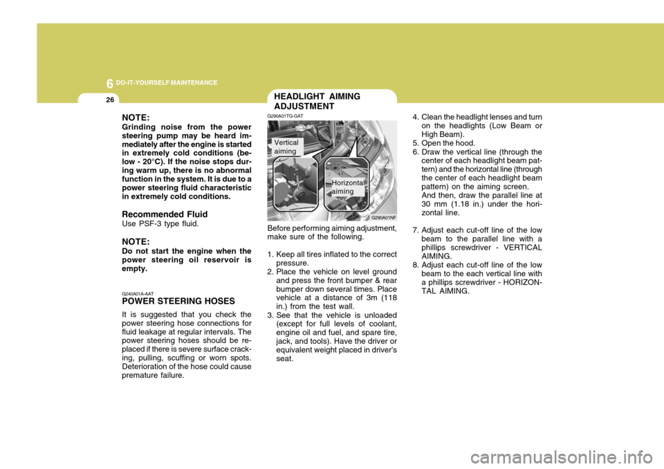
Before performing aiming adjustment, make sure of the following.
1. Keep all tires inflated to the correct pressure.
2. Place the vehicle on level ground and press the front bumper & rear bumper down several times. Place vehicle at a distance of 3m (118 in.) from the test wall.
3. See that the vehicle is unloaded (except for full levels of coolant,engine oil and fuel, and spare tire,jack, and tools). Have the driver or equivalent weight placed in driver's seat.
Vertical aiming
Horizontal aiming 4. Clean the headlight lenses and turn
on the headlights (Low Beam or High Beam).
5. Open the hood.
6. Draw the vertical line (through the center of each headlight beam pat- tern) and the horizontal line (throughthe center of each headlight beam pattern) on the aiming screen. And then, draw the parallel line at 30 mm (1.18 in.) under the hori- zontal line.
7. Adjust each cut-off line of the low beam to the parallel line with a phillips screwdriver - VERTICAL AIMING.
8. Adjust each cut-off line of the low beam to the each vertical line with a phillips screwdriver - HORIZON-TAL AIMING.
NOTE: Grinding noise from the power steering pump may be heard im-mediately after the engine is started in extremely cold conditions (be- low - 20°C). If the noise stops dur-ing warm up, there is no abnormal function in the system. It is due to a power steering fluid characteristicin extremely cold conditions.
Recommended Fluid Use PSF-3 type fluid. NOTE: Do not start the engine when the power steering oil reservoir is empty. G240A01A-AAT POWER STEERING HOSES It is suggested that you check the power steering hose connections forfluid leakage at regular intervals. The power steering hoses should be re- placed if there is severe surface crack-ing, pulling, scuffing or worn spots. Deterioration of the hose could cause premature failure.
Page 263 of 297

6
DO-IT-YOURSELF MAINTENANCE
27
G290B01TG-GAT
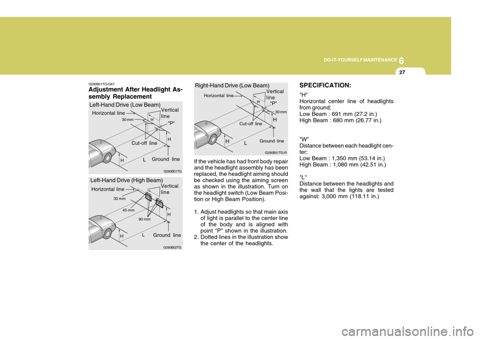
Adjustment After Headlight As- sembly Replacement
G290B01TG
Left-Hand Drive (Low Beam)
G290B01TG-R
Right-Hand Drive (Low Beam)
If the vehicle has had front body repair and the headlight assembly has been replaced, the headlight aiming shouldbe checked using the aiming screen as shown in the illustration. Turn on the headlight switch (Low Beam Posi-tion or High Beam Position).
1. Adjust headlights so that main axis of light is parallel to the center lineof the body and is aligned withpoint "P" shown in the illustration.
2. Dotted lines in the illustration show the center of the headlights. SPECIFICATION: "H" Horizontal center line of headlightsfrom ground; Low Beam : 691 mm (27.2 in.) High Beam : 680 mm (26.77 in.) "W" Distance between each headlight cen-ter;Low Beam : 1,350 mm (53.14 in.) High Beam : 1,080 mm (42.51 in.) "L" Distance between the headlights andthe wall that the lights are testedagainst: 3,000 mm (118.11 in.)
G290B02TG
Left-Hand Drive (High Beam)
LW
H
H Cut-off line
Ground line"P"
Horizontal line
30 mm
L
H 90 mm
Ground line
Horizontal line Vertical line
H45 mm
LW
H Cut-off line
"P"
Horizontal line
Ground line 30 mm
30 mm
Vertical line
Vertical line
H
Page 264 of 297

6 DO-IT-YOURSELF MAINTENANCE
28
Replacement instructions:
1. Allow the bulb to cool. Wear eye protection.
2. Open the engine hood and discon- nect the negative (-) post of the battery.
3. Always grasp the bulb by its plastic base, avoid touching the glass.
G270A01TG-GAT
HEADLIGHT AND FRONT FOG LIGHT
Headlight (High beam) Headlight(Low beam)
G270A01TG
Front Fog Light
REPLACEMENT OF LIGHT BULBS
G260A01TG-GAT Before attempting to replace a light
bulb, be sure the ignition switch is turned to the "OFF" position.
The next paragraph shows how to
reach the light bulbs so they may bechanged. Be sure to replace theburned-out bulb with one of the same number and wattage rating.
See page 6-36 for the wattage descrip-
tions.
! CAUTION:
o Keep the lights out of contact with petroleum products, such as oil, gasoline, etc.
o Be sure to replace the LED type
equipped bulbs with an assem- bly.
o If you don't have necessary tools, the correct bulbs and the exper-tise, consult your authorized Hyundai dealer. CAUTION:
o The headlight aiming should be checked by an authorized Hyundaidealer after replacing the head-light bulbs.
o If your vehicle is equipped with
HID (High Intensity Discharge) type headlight, you must not replace or inspect the headlight. It has a danger of an electric shock. If the headlight is not work- ing, have your vehicle inspectedby your Hyundai Dealer.
! Headlight
Page 293 of 297

10INDEX
2
A Accessory Box .......................................................... 1-95
Air Cleaner Filter ........................................................ 6-10
Air Conditioning Care ........................................................................ 6-18
Filter ............................................................ 1-132, 6-18
Operation .......................................... 1-121, 1-124, 6-18
Switch ........................................................ 1-120, 1-127
Airbag ........................................................................ 1-46
Curtain airbag ......................................................... 1-54
Driver's and passenger's front airbag ...................... 1-47
Passenger's front airbag O N/OFF switch ...............1-51
Side impact airbag .................................................. 1-53
Antenna ................................................................... 1-167
Ashtray ...................................................................... 1-87
Audio System Audio remote control switch ................................. 1-112
Cassette tape player operation (M455) .................1-146
Cassette tape player operation (M465) .................1-156
Compact disc player operation (M445) .................1-139
Compact disc player operation (M455) .................1-149
Compact disc player operation (M465) .................1-159
Stereo radio operation (M445) ..............................1-136
Stereo radio operation (M455) ..............................1-143
Stereo radio operation (M465) ..............................1-153
Automatic Heating and Cooling Control System ...... 1-123BBack Warning
System ............................................... 2-12
Battery .............................................................. 2-17, 6-23
Brake Anti-lock brake system (ABS) ................................ 2-10
Checking the brakes ............................................... 6-16
Fluid ........................................................................ 6-16
Pedal clearance ...................................................... 6-20
Pedal free-play ........................................................ 6-20
Practices ................................................................ 2-13
Breaking-In your New Hyundai .................................... 1-3
C
Care of Cassette Tapes .......................................... 1-165
Care of Discs .......................................................... 1-164
Catalytic Converter ...................................................... 7-3
Child Restraint System .............................................. 1-37
Child-Protector Rear Door Lock ................................. 1-12
Cigarette Lighter ........................................................ 1-85
Clock ......................................................................... 1-85
Combination Light
Auto light ................................................................ 1-78
Daytime running lights ............................................ 1-78
Headlight flasher ..................................................... 1-79
Headlight swi tch ..................................................... 1-77
High-beam switch ................................................... 1-79
Lane change si gnal ................................................. 1-77
Parking light auto cut ............................................. 1-78
Turn signal operation .............................................. 1-77
Page 295 of 297

10INDEX
4
G General Checks ........................................................... 6-3
Glove Box ................................................................. 1-95
HHazard Warning System ............................................ 1-83
Headlight
Aiming adjustment .................................................. 6-26
Leveling device system .......................................... 1-82
Bulb replacement .................................................... 6-28
Switch ..................................................................... 1-77
Washer switch ........................................................ 1-82
Heating and Cooling Control ....................................1-113
Heating and Ventilation ............................................ 1-114
Air flow control ........................................... 1-115, 1-128
Air intake control switch ............................ 1-117, 1-126
Air quality control system ..................................... 1-126
Bi-level heating ..................................................... 1-118
Defrosting/Defogging .................................. 1-119, 1-130
Fan speed control (Blower control) ............ 1-115, 1-125
Temperature control ................................... 1-115, 1-127
High-Mounted Rear Stop Light .................................1-103
Hood Release .......................................................... 1-105
Horn ......................................................................... 1-107
I Ignition Switch ............................................................. 2-3
Immobilizer System ..................................................... 1-5
Limp home procedures ............................................. 1-8
Key ........................................................................... 1-5 Instrument Cluster and
Indicator Lights ..................... 1-58
Instrument Panel Light Control (Rheostat) .................1-85
Intergrated Memory System (I.M.S) ..........................1-26
Interior Light ............................................................... 1-93
Intermittent Wiper ...................................................... 1-82
J Jump Starting .............................................................. 3-3
K
Key .............................................................................. 1-4 If you lose your keys ............................................. 3-13
Positions ................................................................... 2-4
L Light Bulbs Repl acement ........................................... 6-28
Light Bulbs Watages ................................................. 6-36
Lubrication Chart .......................................................... 9-4
M Maintenance Intervals Explanation of scheduled maintenance items ......... 5-7
Maintenance under severe usage conditions .......... 5-6 Scheduled maintenance ........................................... 5-4
Service requirements ................................................ 5-2
Maintenance Precautions ............................................ 6-4
Mirrors
Day/night inside rearview mirror .............................. 1-99
Outside rearview m irror ........................................... 1-96
Outside rearview mirror heater ................................1-98
Page 297 of 297

10INDEX
6
TransaxleAutoma tic ................................................................. 2-5
Automatic transaxle fluid checking ......................... 6-14
Trip Computer ............................................................ 1-73
Trunk Lid ................................................................. 1-100
Trunk lid control button ......................................... 1-101
V Vehicle Identification Number (VIN) ............................. 8-2
Vehicle Specifica tions ................................................. 9-1
WWarning and Indicator Lights ..................................... 1-62
Window Defroster Switch .... .......................................1-84
Windows
Power ..................................................................... 1-17
Windshield Wiper and Washer ...................................1-80
Windshield Wiper Blades .... .......................................6-11