Page 239 of 320
Fuse/Relay
LocationFuse Amp
RatingPassenger Compartment Fuse
Panel Description
23 15A Not used
24 15A Cigar lighter, OBD II, Neutral tow
25 5A Mode-Temperature actuator for
auxiliary climate control, Trailer
tow battery charge relay coil,
TPMS
26 7.5A Reverse park aid, Brake shift
interlock, IVD switch
27 7.5A Automatic dimming mirror, Digital
transmission range sensor, Backup
lamps
28 5A Radio (Start)
29 10A Digital transmission range sensor,
PWR feed to fuse #28 (Start feed)
30 5A Daytime Running Lamps (DRL),
DEATC climate controller, Manual
climate control, Manual climate
control temp blend actuator
REVIEW COPY
2005 Explorer(exp), Owners Guide (post-2002-fmt)(own2002),
Market:USA_English(fus)
Roadside Emergencies
239
Page 240 of 320
Passenger compartment fuse panel (top side)
These relays are located on the reverse side of the passenger
compartment fuse panel. See your dealer or a certified technician for
service of this relay box.
Fuse/Relay Location Description
Relay 1 Flasher
Relay 2 Rear defrost
Relay 3 Delayed accessory
Relay 4 Open
Relay 5 Battery saver
Relay 6 Open
Relay 7 Open
REVIEW COPY
2005 Explorer(exp), Owners Guide (post-2002-fmt)(own2002),
Market:USA_English(fus)
Roadside Emergencies
240
Page 241 of 320
Power distribution box
The power distribution box is
located in the engine compartment.
The power distribution box contains
high-current fuses that protect your
vehicle’s main electrical systems
from overloads.
Always disconnect the battery before servicing high current
fuses.
To reduce risk of electrical shock, always replace the cover to
the Power Distribution Box before reconnecting the battery or
refilling fluid reservoirs.
If the battery has been disconnected and reconnected, refer to the
Batterysection of theMaintenance and Specificationschapter.
REVIEW COPY
2005 Explorer(exp), Owners Guide (post-2002-fmt)(own2002),
Market:USA_English(fus)
Roadside Emergencies
241
Page 242 of 320
The high-current fuses are coded as follows:
Fuse/Relay
LocationFuse Amp
RatingPower Distribution Box
Description
1 60A** PJB #1
2 30A** BSM
3 — Not used
4 30A** Rear defrost
5 40A** Anti-lock Brake System (ABS)
pump
6 60A** Delayed accessory, Power
windows, Audio
7 20A** Power point #2
8 30A** 4x4 shift motor
9 20A** Power point #1
10 30A** ABS module (valves)
11 40A** Powertrain Control Module (PCM)
12 50A** Ignition relay, Starter relay
13 40A** Trailer tow battery charge, Trailer
tow turn signals
14 10A* Daytime Running Lamps (DRL)
(Canada)
REVIEW COPY
2005 Explorer(exp), Owners Guide (post-2002-fmt)(own2002),
Market:USA_English(fus)
Roadside Emergencies
242
Page 245 of 320
The relays are coded as follows:
Fuse/Relay Location Description
Relay 14 Not used
Relay 15 Trailer tow back-up lamps
Relay 16 Not used
Relay 17 Not used
Relay 18 Not used
Relay 19 Trailer tow park lamps
Relay 20 Trailer tow battery charge
Relay 21 Not used
Relay 22 Not used
Relay 23 Not used
Diode 3 Not used
Diode 4 Not used
REVIEW COPY
2005 Explorer(exp), Owners Guide (post-2002-fmt)(own2002),
Market:USA_English(fus)
Roadside Emergencies
245
Page 246 of 320
Auxiliary relay box (Vehicles equipped with 4x4)
The relay box is located on the front
right fender well.
The relays are coded as follows:
Fuse/Relay Location Description
Relay 64 Two-speed 4x4 motor clockwise
Relay 65 Two-speed 4x4 motor counterclockwise
Relay 66 Open
JUMP STARTING YOUR VEHICLE
The gases around the battery can explode if exposed to flames,
sparks, or lit cigarettes. An explosion could result in injury or
vehicle damage.
Batteries contain sulfuric acid which can burn skin, eyes and
clothing, if contacted.
Do not attempt to push-start your vehicle. Automatic
transmissions do not have push-start capability; doing so may
damage the catalytic converter.
REVIEW COPY
2005 Explorer(exp), Owners Guide (post-2002-fmt)(own2002),
Market:USA_English(fus)
Roadside Emergencies
246
Page 247 of 320

Preparing your vehicle
When the battery is disconnected or a new battery is installed, the
transmission must relearn its shift strategy. As a result, the transmission
may have firm and/or soft shifts. This operation is considered normal and
will not affect function or durability of the transmission. Over time, the
adaptive learning process will fully update transmission operation.
1.Use only a 12–volt supply to start your vehicle.
2. Do not disconnect the battery of the disabled vehicle as this could
damage the vehicle’s electrical system.
3. Park the booster vehicle close to the hood of the disabled vehicle
making sure the two vehiclesdo nottouch. Set the parking brake on
both vehicles and stay clear of the engine cooling fan and other moving
parts.
4. Check all battery terminals and remove any excessive corrosion before
you attach the battery cables. Ensure that vent caps are tight and level.
5. Turn the heater fan on in both vehicles to protect any electrical
surges. Turn all other accessories off.
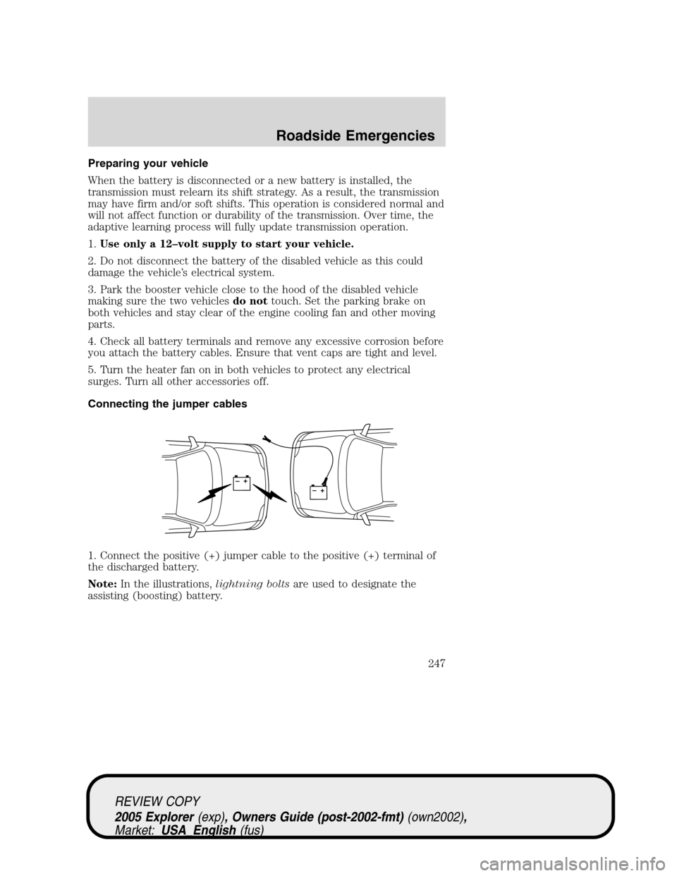
Connecting the jumper cables
1. Connect the positive (+) jumper cable to the positive (+) terminal of
the discharged battery.
Note:In the illustrations,lightning boltsare used to designate the
assisting (boosting) battery.
+–+–
REVIEW COPY
2005 Explorer(exp), Owners Guide (post-2002-fmt)(own2002),
Market:USA_English(fus)
Roadside Emergencies
247
Page 248 of 320
2. Connect the other end of the positive (+) cable to the positive (+)
terminal of the assisting battery.
3. Connect the negative (-) cable to the negative (-) terminal of the
assisting battery.
+–+–
+–+–
REVIEW COPY
2005 Explorer(exp), Owners Guide (post-2002-fmt)(own2002),
Market:USA_English(fus)
Roadside Emergencies
248