2005 FIAT DUCATO 244 fan
[x] Cancel search: fanPage 61 of 258

60GETTING TO KNOW YOUR VEHICLE
– a control unit connected to the
heater/ventilation unit for automatic
operation;
– an electronic control unit to check
and adjusted the integrated heater
burner;
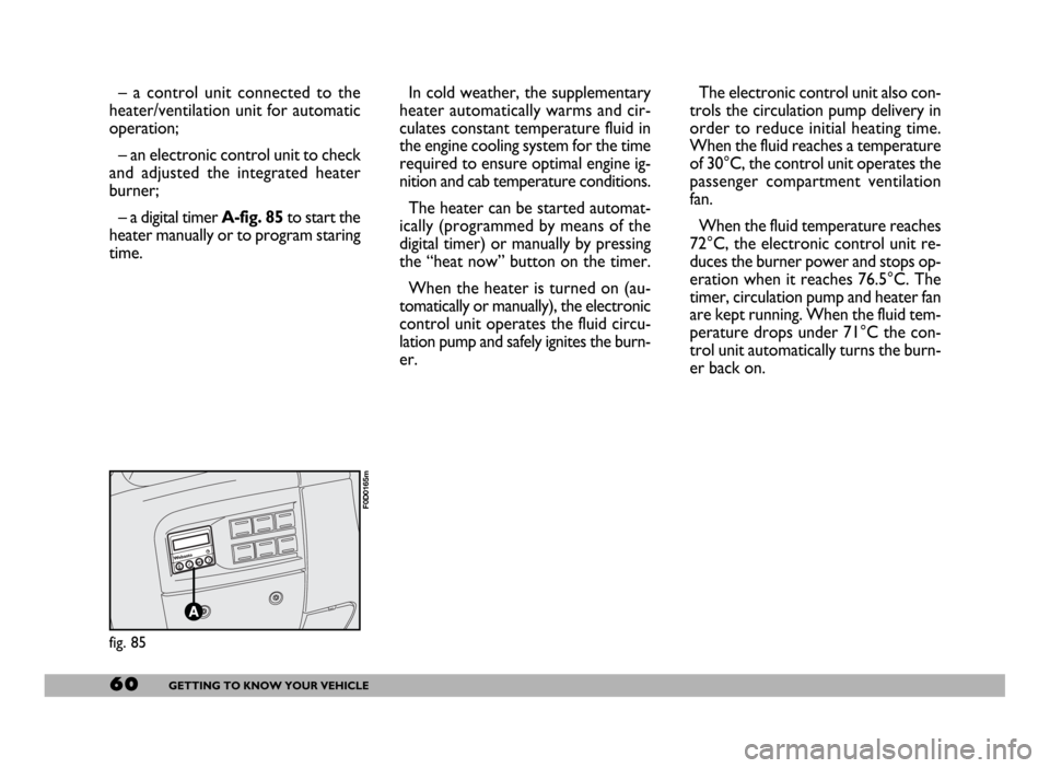
– a digital timer A-fig. 85to start the
heater manually or to program staring
time.In cold weather, the supplementary
heater automatically warms and cir-
culates constant temperature fluid in
the engine cooling system for the time
required to ensure optimal engine ig-
nition and cab temperature conditions.
The heater can be started automat-
ically (programmed by means of the
digital timer) or manually by pressing
the “heat now” button on the timer.
When the heater is turned on (au-
tomatically or manually), the electronic
control unit operates the fluid circu-
lation pump and safely ignites the burn-
er.The electronic control unit also con-
trols the circulation pump delivery in
order to reduce initial heating time.
When the fluid reaches a temperature
of 30°C, the control unit operates the
passenger compartment ventilation
fan.
When the fluid temperature reaches
72°C, the electronic control unit re-
duces the burner power and stops op-
eration when it reaches 76.5°C. The
timer, circulation pump and heater fan
are kept running. When the fluid tem-
perature drops under 71°C the con-
trol unit automatically turns the burn-
er back on.
fig. 85
F0D0165m
Page 62 of 258

61GETTING TO KNOW YOUR VEHICLE
IMPORTANTThe heater is
equipped with a thermal switch which
cuts off the heater in the event of
overheating caused by low or leaking
coolant. In this case, press the pro-
gram selection button to start the
heater again after repairing the cool-
ing system fault and/or topping up the
fluid.
The heater can turn itself off after en-
gine ignition or if the flame goes out.
In this case, turn the heater off man-
ually and attempt to turn it back on
again. If you cannot turn the heater on,
contact a Fiat Dealership.Turning the heater on
Before turning the heater on check
that:
– the heating/ventilation unit knob is
turned to “warm air”;
– the heating/ventilation fan speed
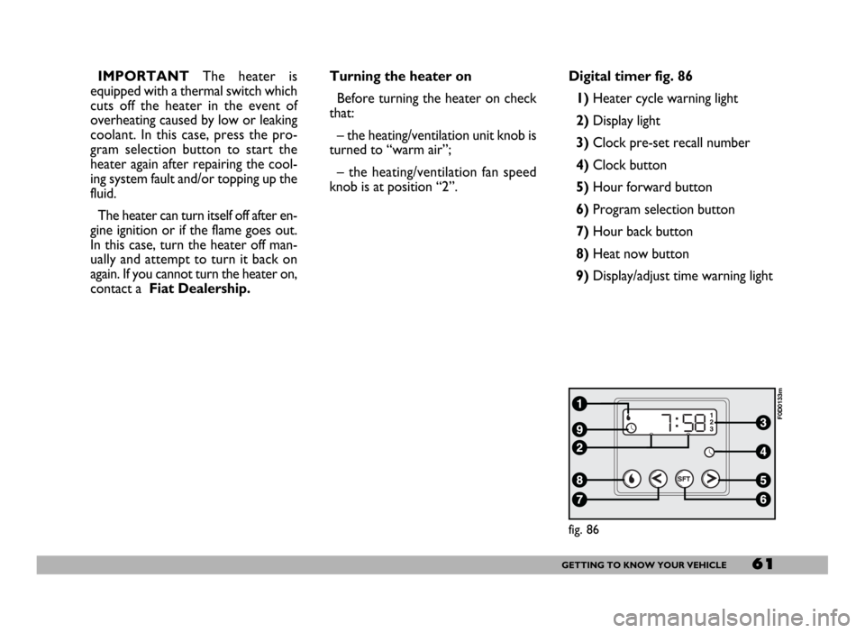
knob is at position “2”.Digital timer fig. 86
1) Heater cycle warning light
2)Display light
3)Clock pre-set recall number
4)Clock button
5)Hour forward button
6)Program selection button
7)Hour back button
8) Heat now button
9) Display/adjust time warning light
fig. 86
F0D0133m
Page 64 of 258

63GETTING TO KNOW YOUR VEHICLE
IMPORTANTTo recall other pre-
set times, press button 6within 10
seconds.
– press button 5or 7to select the
starting time required within 10 sec-
onds.
IMPORTANTStarting time disap-
pears and the number 3(correspond-
ing to the selected preset time) ap-
pears on the display to confirm the
starting time has been entered.
Deleting a programmed
starting time fig. 89
To delete the programmed starting
time, press button 6briefly: the dis-
play light will go off and number 3cor-
responding to the selected preset
time will disappear.Recalling a pre-set time fig. 90
Press the button 6repeatedly until
the required preset starting time ap-
pears on the display (number 3). After
10 seconds, the time will disappear,
number 3and the display will light up
thus confirming starting time has been
entered.
IMPORTANTTo change or delete
pre-set times, follow the instructions
in the paragraphs above.Turning the heater off
According to the operation mode
(automatic or manual), the heater can
be turned off:
–automatically,after the preset
period of time (60 minutes when the
display light is red);
– manuallyby pressing the “heat
now” button on the timer.
In each case, the heater warning light,
the display and the passenger com-
partment fan will be turned off and the
heater flame will be blown out.
The coolant circulation pump will
run for approximately two minutes af-
ter the heater has been turned off to
dispose of as much heat as possible.
During this phase the heater can, how-
ever, be turned on.
fig. 90
F0D0135m
Page 116 of 258

115GETTING THE BEST OUT OF YOUR VEHICLE
Moving the lever back to position D
the gearbox instantly resumes the au-
tomatic mode selecting the ratio ac-
cording to the driving characteristics.
IMPORTANTThe electronic con-
trol unit is programmed to change
gear one at a time, therefore repeat-
ed fast actuations will not result in re-
peated engagements of the gears. The
higher or lower gear is engaged mov-
ing the lever to the (+) or (–) position
when the previous request has been
performed.
In the event of a fault to the sequen-
tial manual system, the system will se-
lect the automatic mode.FAILURE INDICATIONS
Automatic gearbox faults are indi-
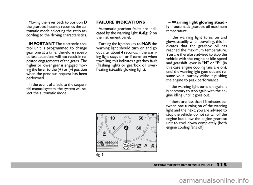
cated by the warning light A-fig. 9 on
the instrument panel.
Turning the ignition key to MARthe
warning light should turn on and go
out after about 4 seconds. If the warn-
ing light stays on or if turns on when
travelling, this indicates a gearbox fault
(flashing light) or gearbox oil over-
heating (steadily glowing light).– Warning light glowing steadi-
ly= automatic gearbox oil maximum
temperature.
If the warning light turns on and
glows steadily when travelling, this in-
dicates that the gearbox oil has
reached the maximum temperature.
You are therefore advised to stop the
vehicle with the engine at idle speed
and gearshift lever in “N” or “P” (in
this case engine cooling fans are on),
until the warning light goes out and re-
sume your journey without pushing
the engine to peak performance.
If the warning light turns on again, it
is necessary to stop again with the en-
gine idling until it goes out.
If there are less than 15 minutes be-
tween one turning on of the warning
light and the next, you are advised to
stop the vehicle, do not switch off the
engine but allow the engine-gearbox
unit to cool down completely (both
engine cooling fans off).
fig. 9
F0D0192m
Page 126 of 258

125GETTING THE BEST OUT OF YOUR VEHICLE
Electric devices
Use electric devices for the neces-
sary time only. The heated rear win-
dow, fog lights, windscreen wipers,
heater fan require large amounts of
electricity and increasing the request
for power will also increase fuel con-
sumption (up to +25% when driving in
towns).
Climate control system
The climate control system is an ad-
ditional load which greatly affects the
engine leading to higher consumption.
When the temperature outside the
vehicle allows it, use the air vents
where possible.
DRIVING STYLE
Starting
Do not warm the engine when the
vehicle is stationary or at high or low
speed: in this way the engine will warm
up gradually increasing consumption
and emissions. You should drive off
slowly straight away avoiding high revs
so that the engine will warm up more
quickly.Unnecessary actions
Avoid revving the engine when
stopped at traffic lights or before
switching off the engine and avoid dou-
bling the clutch as these actions have
no purpose on modern vehicles and
serve only to increase consumption
and pollution.
Gear selections
As soon as the traffic and road con-
ditions allow it, shift to a higher gear.
Using a low gear to liven up accelera-
tion greatly increases consumption. In
the same way improper use of high
gears will increase consumption, emis-
sions and engine wear.
On passenger transportation versions
fitted with 2.3, 2.8 JTD and 2.8 JTD
POWER engines, fuel consumption can
be optimised by starting (on level road)
in 2nd gear instead of 1st gear.Top speeds
Fuel consumption increases consid-
erably as speed increases. Your speed
should be kept as even as possible and
superfluous braking and acceleration
avoided as this increases both con-
sumption and emissions.
Acceleration
Accelerating violently increasing the
revs will greatly affect consumption
and emissions; acceleration should be
gradual and should not exceed the
maximum torque.
Page 154 of 258

153IN AN EMERGENCY
System/Component
CBA (battery fusebox)
Body-builders’ current socket
Alternator
Alternator (2.0 - 2.0 JTD with heating system)
Alternator (2.8 JTD with heating system - 2.0 JTD
with climate control system)
CVM protection
CFO protection
CFO (optional fusebox under the dashboard on passenger’s side
for LH drive versions, on driver’s side for RH drive versions)
Webasto unit
Additional climate control
Chronotachograph
Phone
Alarm
Remote control
ABI for right power window
ABI for door lock
Alarm blinker
Rotating lights (Ambulance versions)
Webasto timer
ABI for left power window
Food box power
Additional heater fan
Left heated rear window
Door mirror defrosting device
Right heated rear window
Driver’s seat warmerFuse no.
F 73
F 72
F 72
F 72
F 70
F 71
F 61
F 56
F 34
F 34
F 34
F 34
F 48
F 38
F 60
F 63
F 58
F 47
F 59
F 57
F 54
F 41
F 40
F 45Ampere
70
125
70
100
150
80
20
30
10
10
10
10
20
20
10
30
5
20
15
15
15
10
15
15Location
Fig. 34
Fig. 34
Fig. 34
Fig. 34
Fig. 34
Fig. 34
Fig. 38
Fig. 38
Fig. 38
Fig. 38
Fig. 38
Fig. 38
Fig. 38
Fig. 38
Fig. 38
Fig. 38
Fig. 38
Fig. 38
Fig. 38
Fig. 38
Fig. 38
Fig. 38
Fig. 38
Fig. 38
Page 155 of 258

154IN AN EMERGENCY
System/Component
Rear current socket
Siren (Ambulance versions)
Suction fan (Minibus versions)
Current socket for special set-up
CFB (main fusebox under the dashboard on driver’s side for
LH drive versions, on passenger’s side for RH drive versions)
Windscreen washer pump
Cigar lighter
Cab heater fan
Direction indicators
Hazard lights
Instrument panel
Cab lights
EOBD diagnostic socket
Rear fog lights
Radio
Front current socket
Headlight washer pump
Front right-hand side light
Rear right-hand side light
Front left-hand side light
Rear left-hand side light
Number plate lights
Side/taillight warning light
Control lights
PCA (Ambulance - Minibus versions)
Radio
ABI
Door power window controlLocation
Fig. 38
Fig. 38
Fig. 38
Fig. 38
Fig. 36
Fig. 36
Fig. 36
Fig. 36
Fig. 36
Fig. 36
Fig. 36
Fig. 36
Fig. 36
Fig. 36
Fig. 36
Fig. 36
Fig. 36
Fig. 36
Fig. 36
Fig. 36
Fig. 36
Fig. 36
Fig. 36
Fig. 36
Fig. 36
Fig. 36
Fig. 36 Ampere
20
20
20
10
15
15
30
10
10
10
10
10
7,5
15
20
15
5
5
5
5
5
5
5
10
7.5
7.5
7.5 Fuse no.
F 64
F 64
F 64
F 65
F 43
F 44
F 55
F 53
F 53
F 53
F 39
F 39
F 33
F 32
F 52
F 49
F 12
F 12
F 13
F 13
F 24
F 24
F 24
F 51
F 25
F 35
F 35
Page 156 of 258

155IN AN EMERGENCY
System/Component
ABS control unit
Airbag control unit
Power mirrors
Cruise control
Phone
Chronotachograph
Remote control
Alarm
Brake lights
Instrument panel
PCC
Ignition switch
Cab fan (with Webasto system)
Webasto control unit
Cab fan (with climate control)
CVM (engine compartment fusebox)
Radiator fan low-speed resistor (2.0 with climate control system)
Engine control unit (2.0 with climate control system)
Engine cooling fan (2.0 with climate control system)
Engine control unit (2.0 with climate control system)
Engine cooling fan (2.0 with climate control system)
Engine control unit (2.0 with climate control system)
CFB protection
E.I. primary services
E.I. primary services
E.I. secondary services
Horn
Steering column stalk controlFuse no.
F 42
F 50
F 27
F 27
F 27
F 27
F 27
F 27
F 26
F 37
F 37
F 31
F 55
F 55
F 55
F 06
F 06
F 06
F 06
F 07
F 07
F 01
F 17
F 22
F 11
F 10
F 10Ampere
7.5
7.5
7.5
7.5
7.5
7.5
7.5
7.5
7.5
10
10
10
30
30
30
40
40
40
40
40
40
60
5
20
10
15
15Location
Fig. 36
Fig. 36
Fig. 36
Fig. 36
Fig. 36
Fig. 36
Fig. 36
Fig. 36
Fig. 36
Fig. 36
Fig. 36
Fig. 36
Fig. 36
Fig. 36
Fig. 36
Fig. 41
Fig. 41
Fig. 41
Fig. 41
Fig. 41
Fig. 41
Fig. 41
Fig. 41
Fig. 41
Fig. 41
Fig. 41
Fig. 41