Page 354 of 462
Downloaded from www.Manualslib.com manuals search engine 348
CLUTCH
GEARBOX
TRANSMISSION
C4 - XSARA - XSARA PICASSOTIGHTENING TORQUES: AL4 AUTOMATIC GEARBOX
Engines: NFU - RFJ
B2CP3EED
B2CP3X8C
Tightening torques (m.daN).
(8) Fixing of converter on diaphragm
Pre-tightening: 1 ± 0,1
Tightening: 3 ± 0,3
(9)Plug fixing: 0,8 ± 0,2
(10)Gearbox fixing on engine: 5,2 ± 1
Hydraulic block fixing.
Centre the hydraulic block, using screws (11) and (12)
Pre-tighten
(no strict order): 0,9
Slacken: All 7 screws
Tighten
(respect the order indicated): 0,75
NOTE: The screw (11)is shouldered.
Angl.-t2-page306-360-2005 9/01/06 10:20 Page 348
Page 355 of 462
Downloaded from www.Manualslib.com manuals search engine 349
CLUTCH
GEARBOX
TRANSMISSION
Engines: NFU - RFJ
B2CP3EGC
(13)Fixing of selector lever position switch: 1,5 ± 0,2
(14)Oil filler plug: 2,4 ± 0,4
TIGHTENING TORQUES: AL4 AUTOMATIC GEARBOXC4 - XSARA - XSARA PICASSO
Angl.-t2-page306-360-2005 9/01/06 10:20 Page 349
Page 358 of 462

Downloaded from www.Manualslib.com manuals search engine 352
CLUTCH
GEARBOX
TRANSMISSION
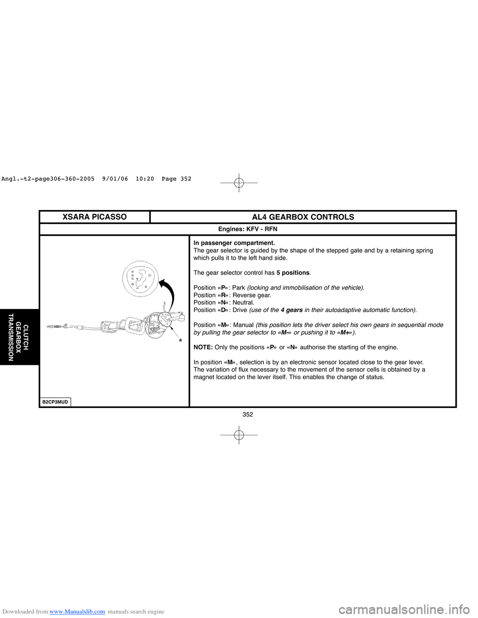
AL4 GEARBOX CONTROLS
In passenger compartment.
The gear selector is guided by the shape of the stepped gate and by a retaining spring
which pulls it to the left hand side.
The gear selector control has 5 positions.
Position «P»: Park
(locking and immobilisation of the vehicle).
Position «R»: Reverse gear.
Position «N»: Neutral.
Position «D»: Drive
(use of the 4 gearsin their autoadaptive automatic function).
Position «M»: Manual (this position lets the driver select his own gears in sequential mode
by pulling the gear selector to «M-»or pushing it to «M+»).
NOTE:Only the positions «P»or «N»authorise the starting of the engine.
In position «M», selection is by an electronic sensor located close to the gear lever.
The variation of flux necessary to the movement of the sensor cells is obtained by a
magnet located on the lever itself. This enables the change of status.
Engines: KFV - RFN
XSARA PICASSO
B2CP3MUD
Angl.-t2-page306-360-2005 9/01/06 10:20 Page 352
Page 359 of 462
Downloaded from www.Manualslib.com manuals search engine 353
CLUTCH
GEARBOX
TRANSMISSION
AL4 GEARBOX CONTROLS
Gearbox end.
The automatic gearbox is controlled by a cable.
«c»or «d»Push-button.
(1)Control lever with ball-joint
(2)Automatic adjustment
(pull out the button to adjust the control, push it in to lock the
adjustment of the control)
(3)Sleeve stop
(4)Selection control locking clip (5)on the sleeve stop (3)
Engines: KFV - RFN
C4 - XSARA - XSARA PICASSO
B2CP3N7C
Angl.-t2-page306-360-2005 9/01/06 10:20 Page 353
Page 364 of 462
Downloaded from www.Manualslib.com manuals search engine 358
CLUTCH
GEARBOX
TRANSMISSION
RECOMMENDATIONS/PRECAUTIONS: AL4 AUTOMATIC GEARBOX (SHIFT LOCK)
SHIFT LOCK.
NOTE: The«shift lock» is a system that locks the gear selection lever in position«P».
Unlocking the «SHIFT LOCK»
(normal operation).
- Switch on the ignition.
- Press the brake pedal and keep it pressed.
- Move the gear selection lever out of position«P».
Unlocking the «SHIFT LOCK»
(with an operating fault).
NOTE:It is impossible to unlock the«shift lock» with the«Normal operation» method.
The fault may originate from one of the following components:
- «Shift lock».
- Gear lever position switch.
- Automatic gearbox ECU.
- Electrical harnesses.
- Battery voltage.
Remove:
- Unlock the«shift lock» by pressing at «a» with a screwdriver placed in the gear
selection control gate.
- Move the gear selection lever out of position«P».
Engine: RFN
XSARA PICASSO
B2CP3N8C
Angl.-t2-page306-360-2005 9/01/06 10:20 Page 358
Page 365 of 462
Downloaded from www.Manualslib.com manuals search engine 359
CLUTCH
GEARBOX
TRANSMISSION
AL4 GEARBOX CONTROLS
Refitting.
Proceed in the opposite order to removal.
Lubricate the support (13).
New gear selection control.
Couple the ball-joint (6).
WARNING: Do not deform the selection lever on the automatic gearbox.
Push in the component (a)without bending the cable.
Check all the gear selection control positions.
Re-used gear selection control.
Release the component (a).
Couple the ball-joint (6).
Push in the component (a)without bending the cable.
Check all the gear selection control positions.
Engine: RFN
XSARA PICASSO
B2CP3NFD
Angl.-t2-page306-360-2005 9/01/06 10:20 Page 359
Page 366 of 462
Downloaded from www.Manualslib.com manuals search engine 360
CLUTCH
GEARBOX
TRANSMISSION
DRIVESHAFTS - GEARBOX
Tightening torques (m.daN)Gearbox oil seal mandrels
Vehicles GearboxDriveshaft Driveshaft
Engines
bearing nutRH side LH side Toolkit
C4
MA/5ET3J4 TU5JP4
XSARA TU3JP TU5JP4
C4EW10/DV6 7114-T.W 7114-T.X 7116-T
BE4/5All types
XSARA EW7/10J4B DW8
XSARA PICASSO DV6/DW10
C4ML6 DW10BTED4 9017-T.C 5701-T.A 9017-T
TU5JP4 EW10A 2 ± 0,2 32,5 ± 2,6
(-) 0338 J1 (-) 0338 H1
XSARATU5JP EW10J4
+ (-) 0338 J3 (-) 0338 H2
DW10ATED
AL4Seal extractor
RH / LH(-). 0338
XSARA PICASSO EW10J4 (-) 0338 C
(-) 0338 J1 (-) 0338 H1
+ (-) 0338 J3 (-) 0338 H2
Tightening torque (m.daN) for wheel bolts.
C4 = 9 ± 1 XSARA = 8,5 ± 0,8 XSARA PICASSO = 10 ± 1
Angl.-t2-page306-360-2005 9/01/06 10:20 Page 360
Page 394 of 462

Downloaded from www.Manualslib.com manuals search engine 388
AXLES
SUSPENSION
STEERING
H1 = R1 – L1 H1’ = R1 – L1’
H1 = From the front suspension arm linkage bolt axis to the ground.
R1 =Radius of the front wheel when laden.
L1 =From the centre of the wheel to the front suspension arm linkage
bolt axis.
H1' =From the front jacking point to the ground.
L1' =From the front jacking point to the radius of the front wheel when
laden.H2 = R2 - L2
H2 = From the rear axle silentblock face to the ground.
R2 =Radius of the rear wheel when laden.
L2 =From the centre of the wheel to the rear axle silentblock face.
AXLE GEOMETRY
Measurements at reference height
NOTE: To make the setting of reference height easier, it is acceptable to take the measurement from the flange of the jacking point.
WARNING: The values shown should only be used as guides. In case of doubt, check the settings at reference height
Rear heightFront height
B3CP05BCB3CP058DB3DP079C
XSARA PICASSO
Conditions for checking and adjusting: Tyres inflated to correct pressures. Vehicle at reference height. Steering rack locked at mid point(see corresponding operation).
Angl.-t2-page361-397-2005 9/01/06 10:22 Page 388