2005 CHRYSLER VOYAGER Frame
[x] Cancel search: FramePage 1932 of 2339
INSTALLATION
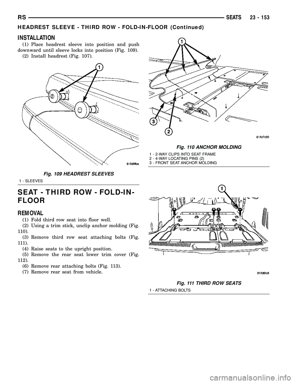
(1) Place headrest sleeve into position and push
downward until sleeve locks into position (Fig. 109).
(2) Install headrest (Fig. 107).
SEAT - THIRD ROW - FOLD-IN-
FLOOR
REMOVAL
(1) Fold third row seat into floor well.
(2) Using a trim stick, unclip anchor molding (Fig.
110).
(3) Remove third row seat attaching bolts (Fig.
111).
(4) Raise seats to the upright position.
(5) Remove the rear seat lower trim cover (Fig.
112).
(6) Remove rear attaching bolts (Fig. 113).
(7) Remove rear seat from vehicle.
Fig. 109 HEADREST SLEEVES
1 - SLEEVES
Fig. 110 ANCHOR MOLDING
1 - 2-WAY CLIPS INTO SEAT FRAME
2 - 4-WAY LOCATING PINS (2)
3 - FRONT SEAT ANCHOR MOLDING
Fig. 111 THIRD ROW SEATS
1 - ATTACHING BOLTS
RSSEATS23 - 153
HEADREST SLEEVE - THIRD ROW - FOLD-IN-FLOOR (Continued)
Page 1934 of 2339
(3) Fold the rear seat into the floor well.
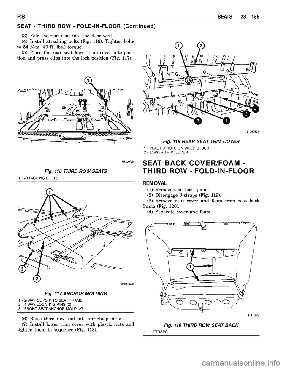
(4) Install attaching bolts (Fig. 116). Tighten bolts
to 54 N´m (40 ft. lbs.) torque.
(5) Place the rear seat lower trim cover into posi-
tion and press clips into the lock position (Fig. 117).
(6) Raise third row seat into upright position.
(7) Install lower trim cover with plastic nuts and
tighten them in sequence (Fig. 118).
SEAT BACK COVER/FOAM -
THIRD ROW - FOLD-IN-FLOOR
REMOVAL
(1) Remove seat back panel.
(2) Disengage J-straps (Fig. 119).
(3) Remove seat cover and foam from seat back
frame (Fig. 120).
(4) Separate cover and foam.
Fig. 116 THIRD ROW SEATS
1 - ATTACHING BOLTS
Fig. 117 ANCHOR MOLDING
1 - 2-WAY CLIPS INTO SEAT FRAME
2 - 4-WAY LOCATING PINS (2)
3 - FRONT SEAT ANCHOR MOLDING
Fig. 118 REAR SEAT TRIM COVER
1 - PLASTIC NUTS ON WELD STUDS
2 - LOWER TRIM COVER
Fig. 119 THIRD ROW SEAT BACK
1 - J-STRAPS
RSSEATS23 - 155
SEAT - THIRD ROW - FOLD-IN-FLOOR (Continued)
Page 1935 of 2339
INSTALLATION
(1) Place seat back foam into cover.
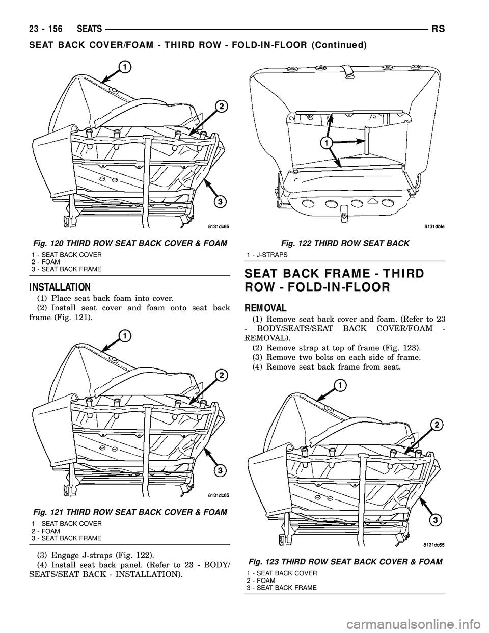
(2) Install seat cover and foam onto seat back
frame (Fig. 121).
(3) Engage J-straps (Fig. 122).
(4) Install seat back panel. (Refer to 23 - BODY/
SEATS/SEAT BACK - INSTALLATION).
SEAT BACK FRAME - THIRD
ROW - FOLD-IN-FLOOR
REMOVAL
(1) Remove seat back cover and foam. (Refer to 23
- BODY/SEATS/SEAT BACK COVER/FOAM -
REMOVAL).
(2) Remove strap at top of frame (Fig. 123).
(3) Remove two bolts on each side of frame.
(4) Remove seat back frame from seat.
Fig. 120 THIRD ROW SEAT BACK COVER & FOAM
1 - SEAT BACK COVER
2 - FOAM
3 - SEAT BACK FRAME
Fig. 121 THIRD ROW SEAT BACK COVER & FOAM
1 - SEAT BACK COVER
2 - FOAM
3 - SEAT BACK FRAME
Fig. 122 THIRD ROW SEAT BACK
1 - J-STRAPS
Fig. 123 THIRD ROW SEAT BACK COVER & FOAM
1 - SEAT BACK COVER
2 - FOAM
3 - SEAT BACK FRAME
23 - 156 SEATSRS
SEAT BACK COVER/FOAM - THIRD ROW - FOLD-IN-FLOOR (Continued)
Page 1936 of 2339
INSTALLATION
(1) Place seat back frame into position.
(2) Install two bolts on each side of seat back
frame.
(3) Install strap at top of frame (Fig. 123).
(4) Install seat back cover and foam. (Refer to 23 -
BODY/SEATS/SEAT BACK COVER - INSTALLA-
TION).
SEAT BELT CENTER LAP BELT
- FOLD-IN-FLOOR
REMOVAL
(1) Set third row seat in the upright position.
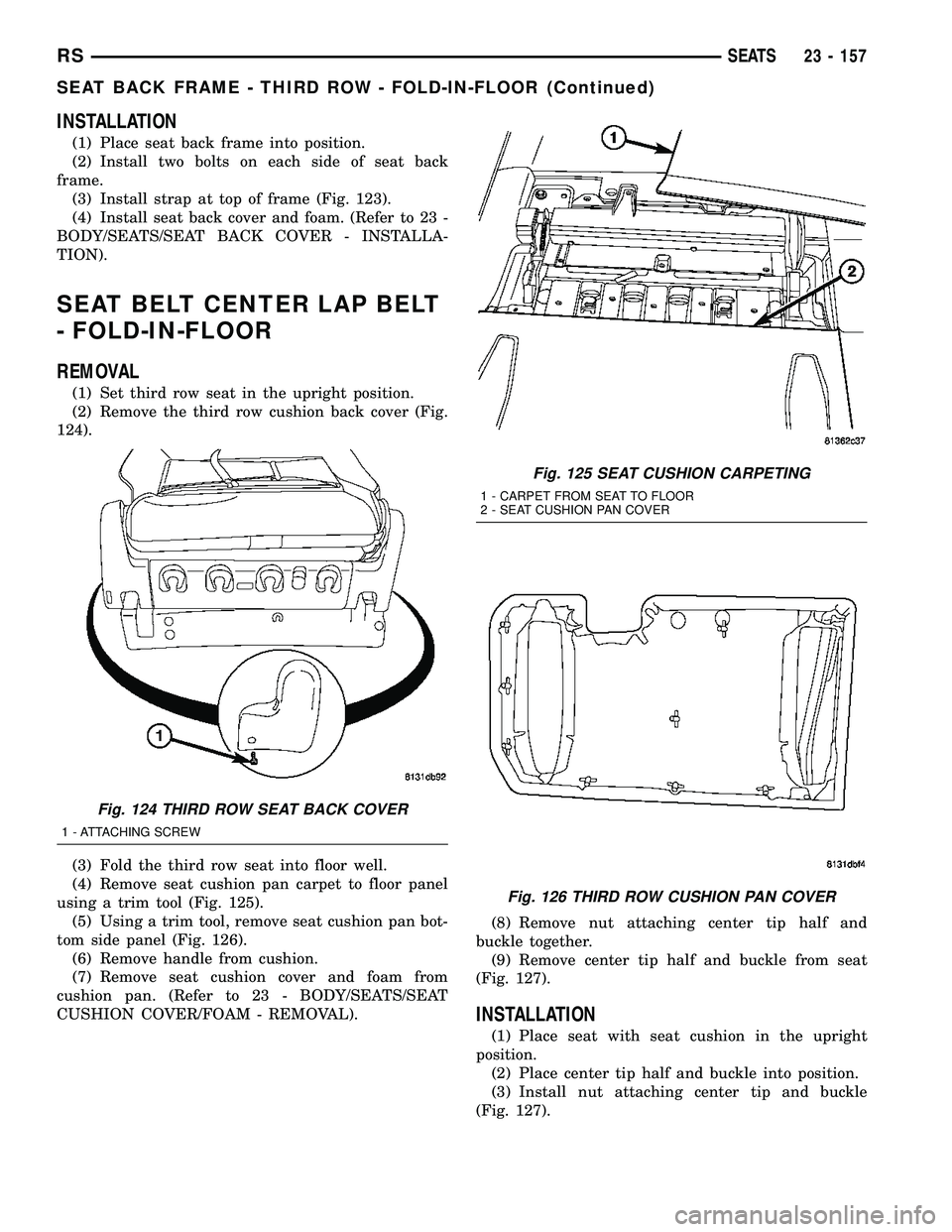
(2) Remove the third row cushion back cover (Fig.
124).
(3) Fold the third row seat into floor well.
(4) Remove seat cushion pan carpet to floor panel
using a trim tool (Fig. 125).
(5) Using a trim tool, remove seat cushion pan bot-
tom side panel (Fig. 126).
(6) Remove handle from cushion.
(7) Remove seat cushion cover and foam from
cushion pan. (Refer to 23 - BODY/SEATS/SEAT
CUSHION COVER/FOAM - REMOVAL).(8) Remove nut attaching center tip half and
buckle together.
(9) Remove center tip half and buckle from seat
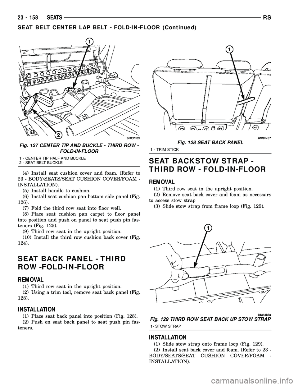
(Fig. 127).
INSTALLATION
(1) Place seat with seat cushion in the upright
position.
(2) Place center tip half and buckle into position.
(3) Install nut attaching center tip and buckle
(Fig. 127).
Fig. 124 THIRD ROW SEAT BACK COVER
1 - ATTACHING SCREW
Fig. 125 SEAT CUSHION CARPETING
1 - CARPET FROM SEAT TO FLOOR
2 - SEAT CUSHION PAN COVER
Fig. 126 THIRD ROW CUSHION PAN COVER
RSSEATS23 - 157
SEAT BACK FRAME - THIRD ROW - FOLD-IN-FLOOR (Continued)
Page 1937 of 2339
(4) Install seat cushion cover and foam. (Refer to
23 - BODY/SEATS/SEAT CUSHION COVER/FOAM -
INSTALLATION).
(5) Install handle to cushion.
(6) Install seat cushion pan bottom side panel (Fig.
126).
(7) Fold the third row seat into floor well.
(8) Place seat cushion pan carpet to floor panel
into position and push on panel to seat push pin fas-
teners (Fig. 125).
(9) Third row seat in the upright position.
(10) Install the third row cushion back cover (Fig.
124).
SEAT BACK PANEL - THIRD
ROW -FOLD-IN-FLOOR
REMOVAL
(1) Third row seat in the upright position.
(2) Using a trim tool, remove seat back panel (Fig.
128).
INSTALLATION
(1) Place seat back panel into position (Fig. 128).
(2) Push on seat back panel to seat push pin fas-
teners.
SEAT BACKSTOW STRAP -
THIRD ROW - FOLD-IN-FLOOR
REMOVAL
(1) Third row seat in the upright position.
(2) Remove seat back cover and foam as necessary
to access stow strap
(3) Slide stow strap from frame loop (Fig. 129).
INSTALLATION
(1) Slide stow strap onto frame loop (Fig. 129).
(2) Install seat back cover and foam. (Refer to 23 -
BODY/SEATS/SEAT CUSHION COVER/FOAM -
INSTALLATION).
Fig. 127 CENTER TIP AND BUCKLE - THIRD ROW -
FOLD-IN-FLOOR
1 - CENTER TIP HALF AND BUCKLE
2 - SEAT BELT BUCKLE
Fig. 128 SEAT BACK PANEL
1 - TRIM STICK
Fig. 129 THIRD ROW SEAT BACK UP STOW STRAP
1- STOW STRAP
23 - 158 SEATSRS
SEAT BELT CENTER LAP BELT - FOLD-IN-FLOOR (Continued)
Page 1939 of 2339
(5) Fold seat into floor well.
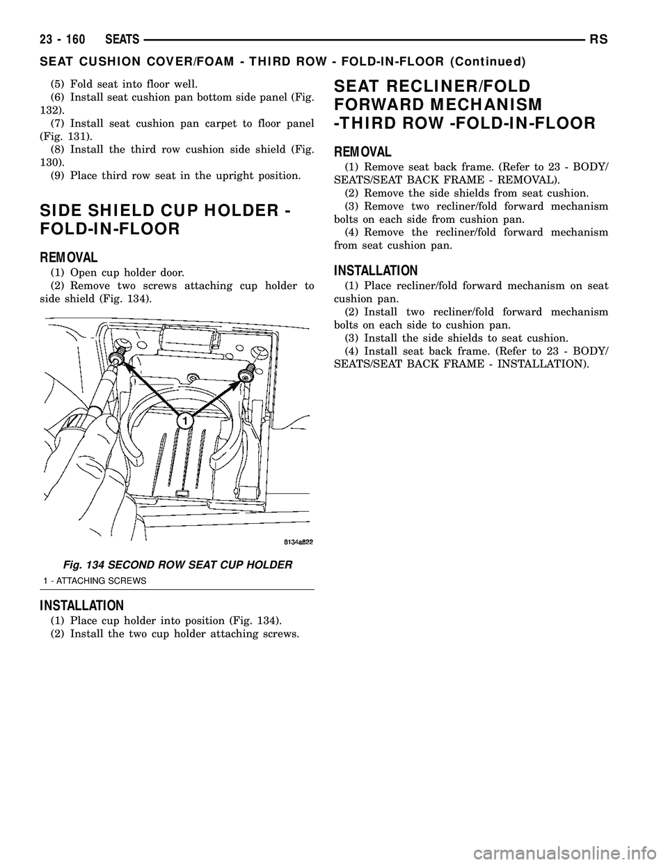
(6) Install seat cushion pan bottom side panel (Fig.
132).
(7) Install seat cushion pan carpet to floor panel
(Fig. 131).
(8) Install the third row cushion side shield (Fig.
130).
(9) Place third row seat in the upright position.
SIDE SHIELD CUP HOLDER -
FOLD-IN-FLOOR
REMOVAL
(1) Open cup holder door.
(2) Remove two screws attaching cup holder to
side shield (Fig. 134).
INSTALLATION
(1) Place cup holder into position (Fig. 134).
(2) Install the two cup holder attaching screws.
SEAT RECLINER/FOLD
FORWARD MECHANISM
-THIRD ROW -FOLD-IN-FLOOR
REMOVAL
(1) Remove seat back frame. (Refer to 23 - BODY/
SEATS/SEAT BACK FRAME - REMOVAL).
(2) Remove the side shields from seat cushion.
(3) Remove two recliner/fold forward mechanism
bolts on each side from cushion pan.
(4) Remove the recliner/fold forward mechanism
from seat cushion pan.
INSTALLATION
(1) Place recliner/fold forward mechanism on seat
cushion pan.
(2) Install two recliner/fold forward mechanism
bolts on each side to cushion pan.
(3) Install the side shields to seat cushion.
(4) Install seat back frame. (Refer to 23 - BODY/
SEATS/SEAT BACK FRAME - INSTALLATION).
Fig. 134 SECOND ROW SEAT CUP HOLDER
1 - ATTACHING SCREWS
23 - 160 SEATSRS
SEAT CUSHION COVER/FOAM - THIRD ROW - FOLD-IN-FLOOR (Continued)
Page 1940 of 2339
STATIONARY GLASS
TABLE OF CONTENTS
page page
WINDSHIELD
DESCRIPTION........................161
WARNING
WINDSHIELD SAFETY PRECAUTIONS....161
REMOVAL............................161
INSTALLATION........................162
SLIDING DOOR GLASS
REMOVAL............................163INSTALLATION........................163
QUARTER WINDOW
REMOVAL............................164
INSTALLATION........................164
LIFTGATE GLASS
REMOVAL............................164
INSTALLATION........................164
WINDSHIELD
DESCRIPTION
The windshield is attached to the window frame
with urethane adhesive. The urethane adhesive is
applied cold and seals the surface area between the
window opening and the glass. The primer adheres
the urethane adhesive to the windshield.
It is difficult to salvage a windshield during the
removal operation. The windshield is part of the
structural support for the roof. The urethane bonding
used to secure the windshield to the fence is difficult
to cut or clean from any surface. If the moldings are
set in urethane, it would also be unlikely they could
be salvaged. Before removing the windshield, check
the availability of the windshield and moldings from
the parts supplier.
WARNING
WINDSHIELD SAFETY PRECAUTIONS
WARNING: DO NOT OPERATE THE VEHICLE
WITHIN 24 HOURS OF WINDSHIELD INSTALLATION.
IT TAKES AT LEAST 24 HOURS FOR URETHANE
ADHESIVE TO CURE. IF IT IS NOT CURED, THE
WINDSHIELD MAY NOT PERFORM PROPERLY IN
AN ACCIDENT.
URETHANE ADHESIVES ARE APPLIED AS A SYS-
TEM. USE GLASS CLEANER, GLASS PREP SOL-
VENT, GLASS PRIMER, PVC (VINYL) PRIMER AND
PINCH WELD (FENCE) PRIMER PROVIDED BY THE
ADHESIVE MANUFACTURER. IF NOT, STRUCTURAL
INTEGRITY COULD BE COMPROMISED.
DAIMLERCHRYSLER DOES NOT RECOMMEND
GLASS ADHESIVE BY BRAND. TECHNICIANS
SHOULD REVIEW PRODUCT LABELS AND TECHNI-
CAL DATA SHEETS, AND USE ONLY ADHESIVESTHAT THEIR MANUFACTURES WARRANT WILL
RESTORE A VEHICLE TO THE REQUIREMENTS OF
FMVSS 212. TECHNICIANS SHOULD ALSO INSURE
THAT PRIMERS AND CLEANERS ARE COMPATIBLE
WITH THE PARTICULAR ADHESIVE USED.
BE SURE TO REFER TO THE URETHANE MANU-
FACTURER'S DIRECTIONS FOR CURING TIME
SPECIFICATIONS, AND DO NOT USE ADHESIVE
AFTER ITS EXPIRATION DATE.
VAPORS THAT ARE EMITTED FROM THE URE-
THANE ADHESIVE OR PRIMER COULD CAUSE
PERSONAL INJURY. USE THEM IN A WELL-VENTI-
LATED AREA.
SKIN CONTACT WITH URETHANE ADHESIVE
SHOULD BE AVOIDED. PERSONAL INJURY MAY
RESULT.
ALWAYS WEAR EYE AND HAND PROTECTION
WHEN WORKING WITH GLASS.
CAUTION: Protect all painted and trimmed surfaces
from coming in contact with urethane or primers.
Be careful not to damage painted surfaces when
removing moldings or cutting urethane around
windshield.
REMOVAL
WINDSHIELD REMOVAL ± EXTERIOR METHOD
The urethane adhesive holding the windshield to
the opening pinch weld (fence) can be cut using a
sharp cold knife from the exterior of the vehicle.
Using the cold knife method is effective if the wind-
shield is already broken. If the glass must be sal-
vaged, cutting the urethane adhesive from the
interior of the vehicle using a reciprocating or oscil-
lating power knife is recommended.
(1) Remove inside rear view mirror.
(2) Remove windshield wiper arms.
(3) Remove cowl cover.
RSSTATIONARY GLASS23 - 161
Page 1945 of 2339
WEATHERSTRIP/SEALS
TABLE OF CONTENTS
page page
FRONT DOOR GLASS RUN WEATHERSTRIP
REMOVAL............................166
INSTALLATION........................166
FRONT DOOR OUTER BELT MOLDING
REMOVAL............................167
INSTALLATION........................167
FRONT DOOR WEATHERSTRIP
REMOVAL............................168INSTALLATION........................168
SLIDING DOOR WEATHERSTRIP
REMOVAL............................168
INSTALLATION........................168
FRONT DOOR INNER BELT MOLDING
REMOVAL............................168
INSTALLATION........................168
FRONT DOOR GLASS RUN
WEATHERSTRIP
REMOVAL
(1) Remove door frame closeout moldings.
(2) Pull weatherstrip from glass run channel at
rear of door frame, working from the bottom to the
top.
(3) Disengage clip attaching weatherstrip to door
frame.
(4) Pull weatherstrip from lip along top of door
frame (Fig. 1).
(5) Remove door trim panel.
(6) Remove door speaker, if equipped.
(7) Remove watershed as necessary to gain access
to screw attaching front lower corner of glass run
weatherstrip to inner door panel.
(8) Remove screw attaching glass run weatherstrip
to inner door panel.
(9) Remove inner belt weatherstrip.
(10) Pull weatherstrip from front glass run chan-
nel.
(11) Remove glass run weatherstrip from vehicle.
INSTALLATION
(1) Position glass run weatherstrip on vehicle (Fig.
1).
(2) Insert A-pillar section of the glass run into door
through belt line and lower to bottom of door using
molded corners as a guide.
NOTE: Care must be taken not to damage the medal
bracket when installing through the belt opening.
(3) Locate the top corner portion of the B-pillar
glass run section onto the roll frame and slide it up
until the part bottoms out on the header portion of
the roll frame.
NOTE: Do not JAM the corner into place.
(4) Install the entire B-pillar glass run onto roll
frame.
(5) Working from the B-pillar forward install the
first eight to twelve inches of the header glass run
onto the roll frame.
NOTE: Use care not to push or pull the header sec-
tion and the molded corner out of location.
23 - 166 WEATHERSTRIP/SEALSRS