2005 CHRYSLER VOYAGER Front door
[x] Cancel search: Front doorPage 1873 of 2339
LEFT D-PILLAR TRIM PANEL
REMOVAL
(1) Remove rear header trim cover.
(2) Remove liftgate sill plate.
(3) Remove second row seat belt turning loop on
long wheel base vehicle.
(4) Remove bolt attaching second row seat belt
lower anchor to quarter on short wheel base vehicle.
(5) Disengage hidden clips attaching trim to D-pil-
lar.
(6) Disconnect speaker wire connector, if equipped.
(7) Pass seat belt through slot in D-pillar trim
panel on short wheel base vehicle.
(8) Remove D-pillar trim from vehicle.
INSTALLATION
(1) Pass seat belt through slot in D-pillar trim
panel on short wheel base vehicle.
(2) Position D-pillar trim panel on vehicle.
(3) Connect speaker wire connector to speaker, if
equipped.
(4) Align locating pins on backside of trim panel to
mating holes in inner quarter panel.
(5) Engage hidden clips attaching trim to D-pillar.
(6) Install bolt attaching second row seat belt
lower anchor to quarter on short wheel base vehicle.
Tighten all seat belt bolts to 39 N´m (29 ft. lbs.).
(7) Install second row seat belt turning loop on
long wheel base vehicle.
(8) Install liftgate sill plate.
(9) Install rear header trim cover.
LEFT QUARTER TRIM PANEL
REMOVAL
CAUTION: Disconnect the negative cable clamp
from battery post. Damage to accessory feed circuit
can result.
(1) Remove first row seat.
(2) Remove second row seat, if equipped.
(3) Remove front door sill plate on three door vehi-
cle.
(4) Remove sliding door sill plate on four door
vehicle.
(5) Remove left quarter trim bolster.
(6) Remove C-pillar trim panel.
(7) Remove left D-pillar trim panel.
(8) Remove first row seat belt anchor.
(9) Remove second row seat belt anchor on long
wheel base vehicle.
(10) Remove screws attaching quarter trim to
quarter panel from bolster area.(11) Remove screws attaching rear edge of quarter
trim to attaching bracket or inner quarter trim
panel.
(12) Disconnect wire connector from accessory
power outlet, if equipped.
(13) Remove quarter trim from quarter panel.
(14) Pass front seat belt and turning loop through
slot in quarter trim panel on three door vehicle.
(15) Pass first row seat belt through slot in quar-
ter trim panel.
(16) Pass second row seat belt, if equipped,
through slot in quarter trim panel on long wheel
base vehicle.
(17) Remove quarter trim panel from vehicle.
INSTALLATION
(1) Position quarter trim panel on vehicle.
(2) Pass second row seat belt, if equipped, through
slot in quarter trim panel on long wheel base vehicle.
(3) Pass first row seat belt through slot in quarter
trim panel.
(4) Connect wire connector into accessory power
outlet, if equipped.
(5) Align locating pins on backside of trim panel to
mating holes in inner panels.
(6) Position quarter trim panel on inner quarter
panel.
(7) Install screws attaching rear edge of quarter
trim to attaching bracket or inner quarter panel.
(8) Install screws attaching quarter trim to inner
quarter panel in bolster area.
(9) Install second row seat belts anchor on long
wheel base vehicle. Tighten all seat belt bolts to 39
N´m (29 in. lbs.) torque.
(10) Install first row seat belt anchor.
(11) Install left D-pillar trim panel.
(12) Install C-pillar trim panel.
(13) Install upper left B-pillar trim on three door
vehicle.
(14) Install left quarter trim bolster.
(15) Install front door sill plate on three door vehi-
cle.
(16) Install sliding door sill plate on four door
vehicle.
(17) Install second row seat, if equipped.
(18) Install first row seat.
(19) Connect the battery negative cable.
LIFTGATE SILL PLATE
REMOVAL
(1) Disengage hidden clips holding sill plate to lift-
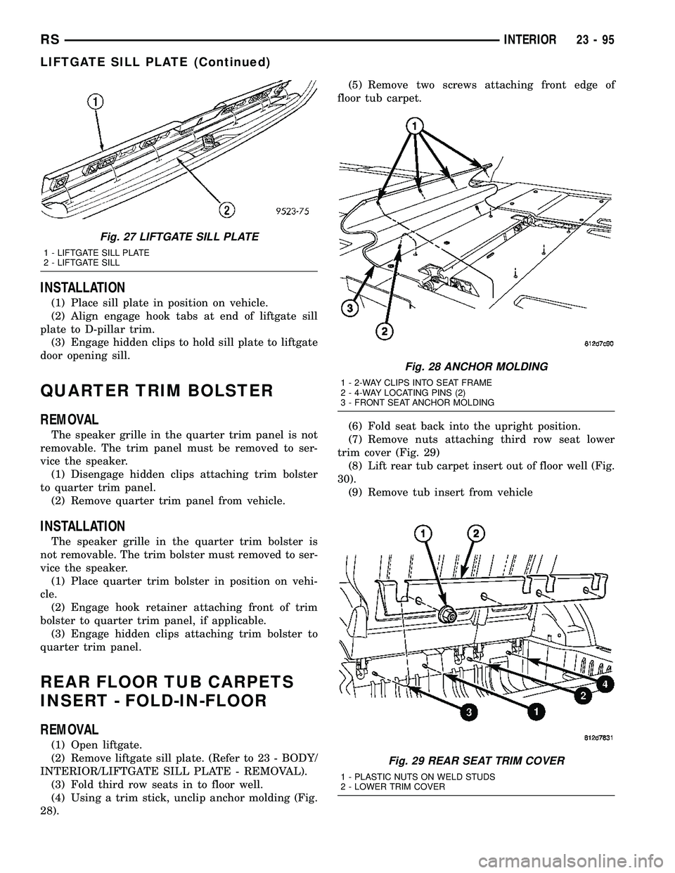
gate door opening sill (Fig. 27).
(2) Remove sill plate from vehicle.
23 - 94 INTERIORRS
Page 1874 of 2339
INSTALLATION
(1) Place sill plate in position on vehicle.
(2) Align engage hook tabs at end of liftgate sill
plate to D-pillar trim.
(3) Engage hidden clips to hold sill plate to liftgate
door opening sill.
QUARTER TRIM BOLSTER
REMOVAL
The speaker grille in the quarter trim panel is not
removable. The trim panel must be removed to ser-
vice the speaker.
(1) Disengage hidden clips attaching trim bolster
to quarter trim panel.
(2) Remove quarter trim panel from vehicle.
INSTALLATION
The speaker grille in the quarter trim bolster is
not removable. The trim bolster must removed to ser-
vice the speaker.
(1) Place quarter trim bolster in position on vehi-
cle.
(2) Engage hook retainer attaching front of trim
bolster to quarter trim panel, if applicable.
(3) Engage hidden clips attaching trim bolster to
quarter trim panel.
REAR FLOOR TUB CARPETS
INSERT - FOLD-IN-FLOOR
REMOVAL
(1) Open liftgate.
(2) Remove liftgate sill plate. (Refer to 23 - BODY/
INTERIOR/LIFTGATE SILL PLATE - REMOVAL).
(3) Fold third row seats in to floor well.
(4) Using a trim stick, unclip anchor molding (Fig.
28).(5) Remove two screws attaching front edge of
floor tub carpet.
(6) Fold seat back into the upright position.
(7) Remove nuts attaching third row seat lower
trim cover (Fig. 29)
(8) Lift rear tub carpet insert out of floor well (Fig.
30).
(9) Remove tub insert from vehicle
Fig. 27 LIFTGATE SILL PLATE
1 - LIFTGATE SILL PLATE
2 - LIFTGATE SILL
Fig. 28 ANCHOR MOLDING
1 - 2-WAY CLIPS INTO SEAT FRAME
2 - 4-WAY LOCATING PINS (2)
3 - FRONT SEAT ANCHOR MOLDING
Fig. 29 REAR SEAT TRIM COVER
1 - PLASTIC NUTS ON WELD STUDS
2 - LOWER TRIM COVER
RSINTERIOR23-95
LIFTGATE SILL PLATE (Continued)
Page 1876 of 2339
INSTALLATION
(1) Place bezel in position in HVAC duct opening.
(2) Push inward on bezel until clips snap in place.
Verify that all four clips have been engaged to the
bezel and that the bezel is flush to the headlining
(3) Position HVAC louver to bezel.
(4) Snap both ends of the louver into HVAC bezel.
RIGHT QUARTER TRIM PANEL
REMOVAL
CAUTION: Disconnect the battery negative cable.
Damage to accessory feed circuit can result.
(1) Remove first row seat.
(2) Remove second row seat.
(3) Remove sliding door sill trim panel.
(4) Remove quarter trim bolster.
(5) Remove D-pillar trim panel.
(6) Remove first row seat belt anchor.
(7) Remove second row seat belt anchor.
(8) Remove screws attaching quarter trim to quar-
ter panel from bolster area.
(9) Remove screws attaching rear edge of quarter
trim to attaching bracket.
(10) Disengage hidden clips attaching front of
quarter trim to quarter panel rearward of sliding
door opening and at locators.
(11) Remove quarter trim from quarter panel.
(12) Disconnect speaker wire connector on LWB
quarter trim panel with rear air conditioning.
(13) Pass second row seat belt through slot in trim
panel on long wheel base vehicle.
(14) Pass first row seat belt through slot in trim
panel.
(15) Remove quarter trim panel from vehicle.
INSTALLATION
(1) Position quarter trim panel on vehicle.
(2) Pass first row seat belt through slot in trim
panel.
(3) Pass second row seat belt through access hole
in trim panel on long wheel base vehicle.
(4) Connect wire connector into speaker on LWB
with rear air conditioning.
(5) Align locating pins on backside of trim panel to
mating holes in inner quarter panel.
(6) Engage hidden clips attaching front of quarter
trim to quarter panel rearward of sliding door open-
ing and at locators.
(7) Install screws attaching rear edge of quarter
trim to attaching bracket.
(8) Install screws attaching quarter trim to inner
quarter panel in bolster area.(9) Install second row seat belt anchor on long
wheel base vehicle. Tighten all seat belt bolts to 39
N´m (29 ft. lbs.) torque.
(10) Install first row seat belt anchor.
(11) Install D-pillar trim panel.
(12) Install C-pillar trim panel.
(13) Install quarter trim bolster.
(14) Install sliding door sill trim panel.
(15) Install second row seat, if equipped.
(16) Install first row seat.
(17) Connect the battery negative cable.
REAR VIEW MIRROR
REMOVAL
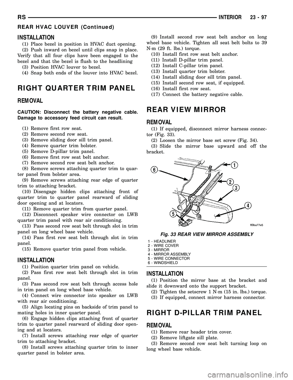
(1) If equipped, disconnect mirror harness connec-
tor (Fig. 33).
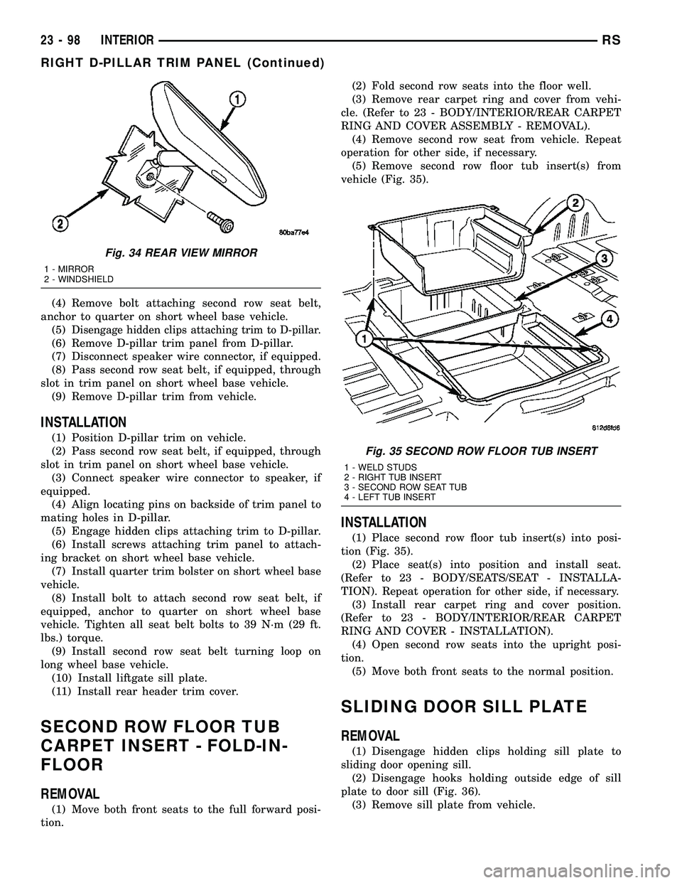
(2) Loosen the mirror base set screw (Fig. 34).
(3) Slide the mirror base upward and off the
bracket.
INSTALLATION
(1) Position the mirror base at the bracket and
slide it downward onto the support bracket.
(2) Tighten the setscrew 1 N´m (15 in. lbs.) torque.
(3) If equipped, connect mirror harness connector.
RIGHT D-PILLAR TRIM PANEL
REMOVAL
(1) Remove rear header trim cover.
(2) Remove liftgate sill plate.
(3) Remove second row seat belt turning loop on
long wheel base vehicle.
Fig. 33 REAR VIEW MIRROR ASSEMBLY
1 - HEADLINER
2 - WIRE COVER
3 - MIRROR
4 - MIRROR ASSEMBLY
5 - WIRE CONNECTOR
6 - WINDSHIELD
RSINTERIOR23-97
REAR HVAC LOUVER (Continued)
Page 1877 of 2339
(4) Remove bolt attaching second row seat belt,
anchor to quarter on short wheel base vehicle.
(5)
Disengage hidden clips attaching trim to D-pillar.
(6) Remove D-pillar trim panel from D-pillar.
(7) Disconnect speaker wire connector, if equipped.
(8) Pass second row seat belt, if equipped, through
slot in trim panel on short wheel base vehicle.
(9) Remove D-pillar trim from vehicle.
INSTALLATION
(1) Position D-pillar trim on vehicle.
(2) Pass second row seat belt, if equipped, through
slot in trim panel on short wheel base vehicle.
(3) Connect speaker wire connector to speaker, if
equipped.
(4) Align locating pins on backside of trim panel to
mating holes in D-pillar.
(5) Engage hidden clips attaching trim to D-pillar.
(6) Install screws attaching trim panel to attach-
ing bracket on short wheel base vehicle.
(7) Install quarter trim bolster on short wheel base
vehicle.
(8) Install bolt to attach second row seat belt, if
equipped, anchor to quarter on short wheel base
vehicle. Tighten all seat belt bolts to 39 N´m (29 ft.
lbs.) torque.
(9) Install second row seat belt turning loop on
long wheel base vehicle.
(10) Install liftgate sill plate.
(11) Install rear header trim cover.
SECOND ROW FLOOR TUB
CARPET INSERT - FOLD-IN-
FLOOR
REMOVAL
(1) Move both front seats to the full forward posi-
tion.(2) Fold second row seats into the floor well.
(3) Remove rear carpet ring and cover from vehi-
cle. (Refer to 23 - BODY/INTERIOR/REAR CARPET
RING AND COVER ASSEMBLY - REMOVAL).
(4) Remove second row seat from vehicle. Repeat
operation for other side, if necessary.
(5) Remove second row floor tub insert(s) from
vehicle (Fig. 35).
INSTALLATION
(1) Place second row floor tub insert(s) into posi-
tion (Fig. 35).
(2) Place seat(s) into position and install seat.
(Refer to 23 - BODY/SEATS/SEAT - INSTALLA-
TION). Repeat operation for other side, if necessary.
(3) Install rear carpet ring and cover position.
(Refer to 23 - BODY/INTERIOR/REAR CARPET
RING AND COVER - INSTALLATION).
(4) Open second row seats into the upright posi-
tion.
(5) Move both front seats to the normal position.
SLIDING DOOR SILL PLATE
REMOVAL
(1) Disengage hidden clips holding sill plate to
sliding door opening sill.
(2) Disengage hooks holding outside edge of sill
plate to door sill (Fig. 36).
(3) Remove sill plate from vehicle.
Fig. 34 REAR VIEW MIRROR
1 - MIRROR
2 - WINDSHIELD
Fig. 35 SECOND ROW FLOOR TUB INSERT
1 - WELD STUDS
2 - RIGHT TUB INSERT
3 - SECOND ROW SEAT TUB
4 - LEFT TUB INSERT
23 - 98 INTERIORRS
RIGHT D-PILLAR TRIM PANEL (Continued)
Page 1941 of 2339
(4) Remove A-pillar trim panels.
(5) Place protective covers over instrument panel
and hood.
(6) Remove windshield molding. Using pliers, pull
outward on molding at the bottom of A-pillars.
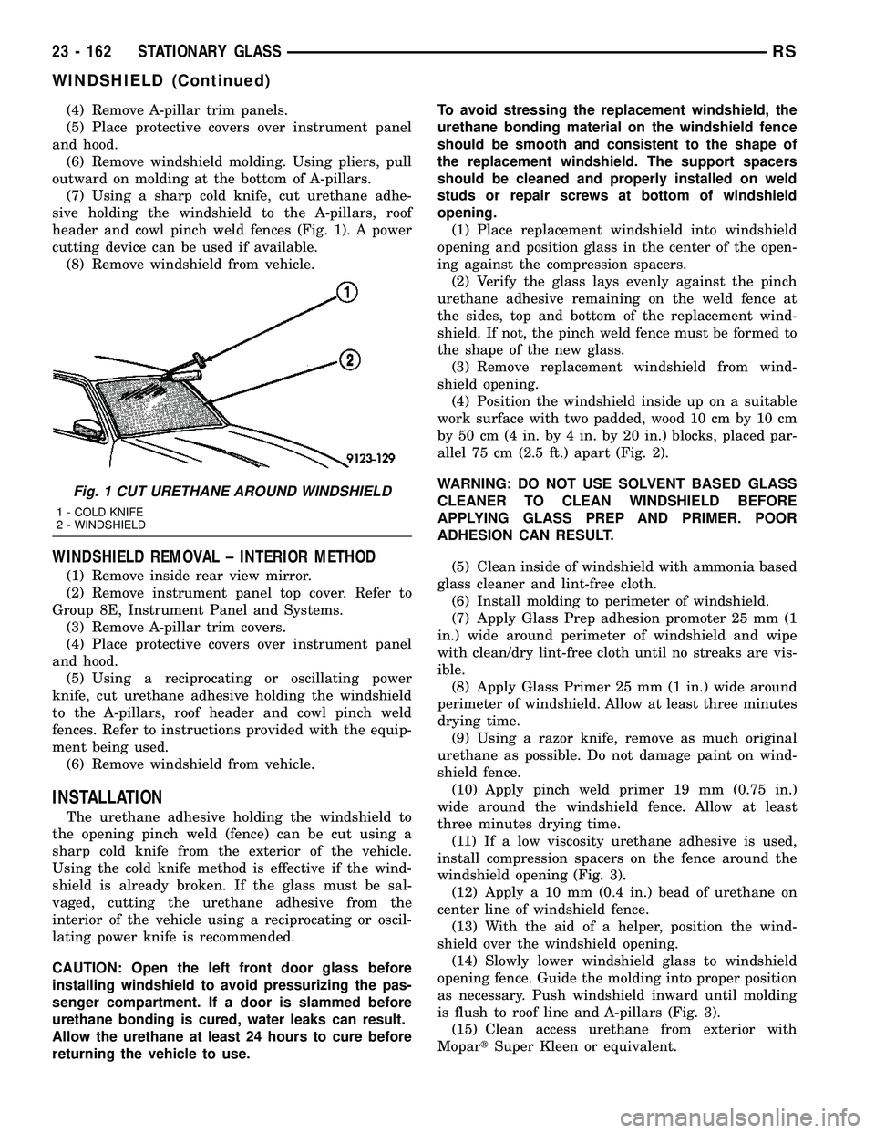
(7) Using a sharp cold knife, cut urethane adhe-
sive holding the windshield to the A-pillars, roof
header and cowl pinch weld fences (Fig. 1). A power
cutting device can be used if available.
(8) Remove windshield from vehicle.
WINDSHIELD REMOVAL ± INTERIOR METHOD
(1) Remove inside rear view mirror.
(2) Remove instrument panel top cover. Refer to
Group 8E, Instrument Panel and Systems.
(3) Remove A-pillar trim covers.
(4) Place protective covers over instrument panel
and hood.
(5) Using a reciprocating or oscillating power
knife, cut urethane adhesive holding the windshield
to the A-pillars, roof header and cowl pinch weld
fences. Refer to instructions provided with the equip-
ment being used.
(6) Remove windshield from vehicle.
INSTALLATION
The urethane adhesive holding the windshield to
the opening pinch weld (fence) can be cut using a
sharp cold knife from the exterior of the vehicle.
Using the cold knife method is effective if the wind-
shield is already broken. If the glass must be sal-
vaged, cutting the urethane adhesive from the
interior of the vehicle using a reciprocating or oscil-
lating power knife is recommended.
CAUTION: Open the left front door glass before
installing windshield to avoid pressurizing the pas-
senger compartment. If a door is slammed before
urethane bonding is cured, water leaks can result.
Allow the urethane at least 24 hours to cure before
returning the vehicle to use.To avoid stressing the replacement windshield, the
urethane bonding material on the windshield fence
should be smooth and consistent to the shape of
the replacement windshield. The support spacers
should be cleaned and properly installed on weld
studs or repair screws at bottom of windshield
opening.
(1) Place replacement windshield into windshield
opening and position glass in the center of the open-
ing against the compression spacers.
(2) Verify the glass lays evenly against the pinch
urethane adhesive remaining on the weld fence at
the sides, top and bottom of the replacement wind-
shield. If not, the pinch weld fence must be formed to
the shape of the new glass.
(3) Remove replacement windshield from wind-
shield opening.
(4) Position the windshield inside up on a suitable
work surface with two padded, wood 10 cm by 10 cm
by 50 cm (4 in. by 4 in. by 20 in.) blocks, placed par-
allel 75 cm (2.5 ft.) apart (Fig. 2).
WARNING: DO NOT USE SOLVENT BASED GLASS
CLEANER TO CLEAN WINDSHIELD BEFORE
APPLYING GLASS PREP AND PRIMER. POOR
ADHESION CAN RESULT.
(5) Clean inside of windshield with ammonia based
glass cleaner and lint-free cloth.
(6) Install molding to perimeter of windshield.
(7) Apply Glass Prep adhesion promoter 25 mm (1
in.) wide around perimeter of windshield and wipe
with clean/dry lint-free cloth until no streaks are vis-
ible.
(8) Apply Glass Primer 25 mm (1 in.) wide around
perimeter of windshield. Allow at least three minutes
drying time.
(9) Using a razor knife, remove as much original
urethane as possible. Do not damage paint on wind-
shield fence.
(10) Apply pinch weld primer 19 mm (0.75 in.)
wide around the windshield fence. Allow at least
three minutes drying time.
(11) If a low viscosity urethane adhesive is used,
install compression spacers on the fence around the
windshield opening (Fig. 3).
(12) Apply a 10 mm (0.4 in.) bead of urethane on
center line of windshield fence.
(13) With the aid of a helper, position the wind-
shield over the windshield opening.
(14) Slowly lower windshield glass to windshield
opening fence. Guide the molding into proper position
as necessary. Push windshield inward until molding
is flush to roof line and A-pillars (Fig. 3).
(15) Clean access urethane from exterior with
MopartSuper Kleen or equivalent.
Fig. 1 CUT URETHANE AROUND WINDSHIELD
1 - COLD KNIFE
2 - WINDSHIELD
23 - 162 STATIONARY GLASSRS
WINDSHIELD (Continued)
Page 1943 of 2339
QUARTER WINDOW
REMOVAL
(1) Remove C-pillar trim.
(2) Open quarter glass to vent position.
(3) Disengage quarter window retainer from vent
motor arm.
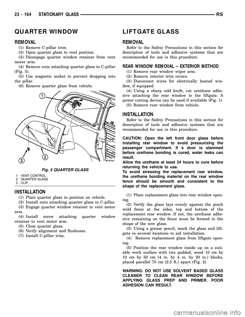
(4) Remove nuts attaching quarter glass to C-pillar
(Fig. 5).
(5) Use magnetic socket to prevent dropping into
the pillar.
(6) Remove quarter glass from vehicle.
INSTALLATION
(1) Place quarter glass in position on vehicle.
(2) Install nuts attaching quarter glass to C-pillar.
(3) Engage quarter window retainer to vent motor
arm.
(4) Install screw attaching quarter window
retainer to vent motor arm.
(5) Close quarter glass.
(6) Verify alignment and flushness.
(7) Install C-pillar trim.
LIFTGATE GLASS
REMOVAL
Refer to the Safety Precautions in this section for
description of tools and adhesive systems that are
recommended for use in this procedure.
REAR WINDOW REMOVAL ± EXTERIOR METHOD
(1) Remove rear window wiper arm.
(2) Remove interior trim covers.
(3) Disconnect wires for electrically heated win-
dow, if equipped.
(4) Using a sharp cold knife, cut urethane adhe-
sive attaching the rear window to the liftgate. A
power cutting device can be used if available (Fig. 1).
(5) Remove rear window from vehicle.
INSTALLATION
Refer to the Safety Precautions in this section for
description of tools and adhesive systems that are
recommended for use in this procedure.
CAUTION: Open the left front door glass before
installing rear window to avoid pressurizing the
passenger compartment. If a door is slammed
before urethane bonding is cured, water leaks can
result.
Allow the urethane at least 24 hours to cure before
returning the vehicle to use.
To avoid stressing the replacement rear window,
the urethane bonding material on the rear window
fence should be smooth and consistent to the
shape of the replacement glass.
(1) Place replacement glass into rear window open-
ing.
(2) Verify the glass lays evenly against the pinch
weld fence at the sides, top and bottom of the
replacement rear window. If not, the urethane adhe-
sive remaining on the fence must be formed to the
shape of the new glass.
(3) Using a grease pencil, mark the glass and lift-
gate in several locations to aid installation.
(4) Remove replacement glass from liftgate open-
ing.
(5) Position the rear window inside up on a suit-
able work surface with two padded, wood 10 cm by
10 cm by 50 cm (4 in. by 4 in. by 20 in.) blocks,
placed parallel 75 cm (2.5 ft.) apart (Fig. 2).
WARNING: DO NOT USE SOLVENT BASED GLASS
CLEANER TO CLEAN REAR WINDOW BEFORE
APPLYING GLASS PREP AND PRIMER. POOR
ADHESION CAN RESULT.
Fig. 5 QUARTER GLASS
1 - VENT CONTROL
2 - QUARTER GLASS
3 - CLIP
23 - 164 STATIONARY GLASSRS
Page 1945 of 2339
WEATHERSTRIP/SEALS
TABLE OF CONTENTS
page page
FRONT DOOR GLASS RUN WEATHERSTRIP
REMOVAL............................166
INSTALLATION........................166
FRONT DOOR OUTER BELT MOLDING
REMOVAL............................167
INSTALLATION........................167
FRONT DOOR WEATHERSTRIP
REMOVAL............................168INSTALLATION........................168
SLIDING DOOR WEATHERSTRIP
REMOVAL............................168
INSTALLATION........................168
FRONT DOOR INNER BELT MOLDING
REMOVAL............................168
INSTALLATION........................168
FRONT DOOR GLASS RUN
WEATHERSTRIP
REMOVAL
(1) Remove door frame closeout moldings.
(2) Pull weatherstrip from glass run channel at
rear of door frame, working from the bottom to the
top.
(3) Disengage clip attaching weatherstrip to door
frame.
(4) Pull weatherstrip from lip along top of door
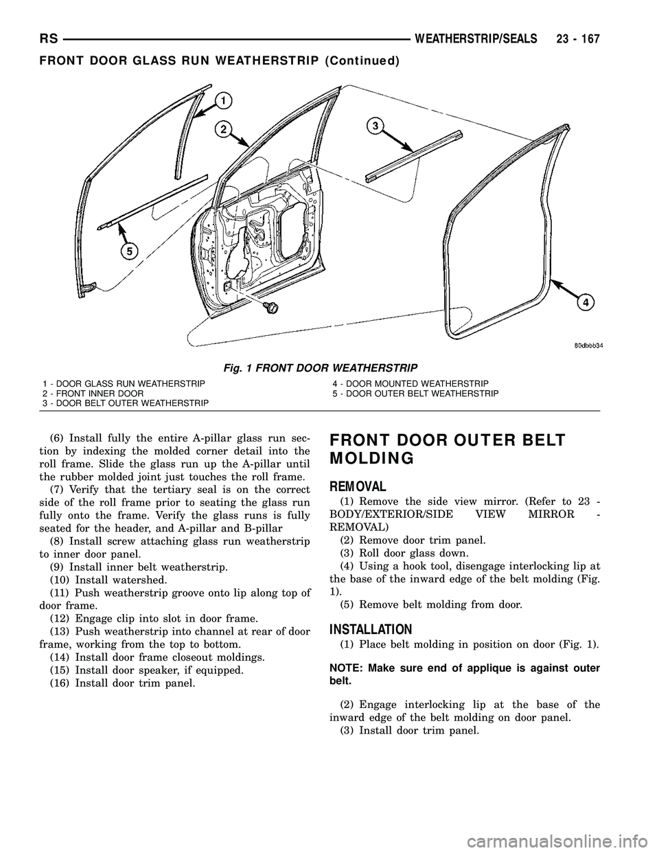
frame (Fig. 1).
(5) Remove door trim panel.
(6) Remove door speaker, if equipped.
(7) Remove watershed as necessary to gain access
to screw attaching front lower corner of glass run
weatherstrip to inner door panel.
(8) Remove screw attaching glass run weatherstrip
to inner door panel.
(9) Remove inner belt weatherstrip.
(10) Pull weatherstrip from front glass run chan-
nel.
(11) Remove glass run weatherstrip from vehicle.
INSTALLATION
(1) Position glass run weatherstrip on vehicle (Fig.
1).
(2) Insert A-pillar section of the glass run into door
through belt line and lower to bottom of door using
molded corners as a guide.
NOTE: Care must be taken not to damage the medal
bracket when installing through the belt opening.
(3) Locate the top corner portion of the B-pillar
glass run section onto the roll frame and slide it up
until the part bottoms out on the header portion of
the roll frame.
NOTE: Do not JAM the corner into place.
(4) Install the entire B-pillar glass run onto roll
frame.
(5) Working from the B-pillar forward install the
first eight to twelve inches of the header glass run
onto the roll frame.
NOTE: Use care not to push or pull the header sec-
tion and the molded corner out of location.
23 - 166 WEATHERSTRIP/SEALSRS
Page 1946 of 2339
(6) Install fully the entire A-pillar glass run sec-
tion by indexing the molded corner detail into the
roll frame. Slide the glass run up the A-pillar until
the rubber molded joint just touches the roll frame.
(7) Verify that the tertiary seal is on the correct
side of the roll frame prior to seating the glass run
fully onto the frame. Verify the glass runs is fully
seated for the header, and A-pillar and B-pillar
(8) Install screw attaching glass run weatherstrip
to inner door panel.
(9) Install inner belt weatherstrip.
(10) Install watershed.
(11) Push weatherstrip groove onto lip along top of
door frame.
(12) Engage clip into slot in door frame.
(13) Push weatherstrip into channel at rear of door
frame, working from the top to bottom.
(14) Install door frame closeout moldings.
(15) Install door speaker, if equipped.
(16) Install door trim panel.FRONT DOOR OUTER BELT
MOLDING
REMOVAL
(1) Remove the side view mirror. (Refer to 23 -
BODY/EXTERIOR/SIDE VIEW MIRROR -
REMOVAL)
(2) Remove door trim panel.
(3) Roll door glass down.
(4) Using a hook tool, disengage interlocking lip at
the base of the inward edge of the belt molding (Fig.
1).
(5) Remove belt molding from door.
INSTALLATION
(1) Place belt molding in position on door (Fig. 1).
NOTE: Make sure end of applique is against outer
belt.
(2) Engage interlocking lip at the base of the
inward edge of the belt molding on door panel.
(3) Install door trim panel.
Fig. 1 FRONT DOOR WEATHERSTRIP
1 - DOOR GLASS RUN WEATHERSTRIP
2 - FRONT INNER DOOR
3 - DOOR BELT OUTER WEATHERSTRIP4 - DOOR MOUNTED WEATHERSTRIP
5 - DOOR OUTER BELT WEATHERSTRIP
RSWEATHERSTRIP/SEALS23 - 167
FRONT DOOR GLASS RUN WEATHERSTRIP (Continued)