2005 CHRYSLER VOYAGER Servo
[x] Cancel search: ServoPage 2180 of 2339
MODE DOOR ACTUATOR
DESCRIPTION
The mode door actuator is a reversible, 12-volt
Direct Current (DC), servo motor. The single mode
door actuator is located on the driver's side end of
the HVAC housing, close to the top of the distribution
housing. The mode door actuator is mechanically con-
nected to the mode door.
The mode door actuator is interchangeable with
the actuators for the blend air door(s) and the recir-
culation air door. Each actuator is contained within
an identical black molded plastic housing with an
integral wire connector receptacle. Two integral
mounting tabs allow the actuator to be secured with
two screws to the distribution housing. Each actuator
also has an identical output shaft with splines that
connects it to the linkage that drives the mode door.
The mode door actuator does not require mechanical
indexing to the mode door linkage, as it is electroni-
cally calibrated by the heater-A/C control module.
OPERATION
The mode door actuator is connected to the A/C-
heater control through the vehicle electrical system
by a dedicated two-wire lead and connector from the
HVAC wire harness. The mode door actuator can
move the mode door in two directions. When the A/C-
heater control pulls the voltage on one side of the
motor connection high and the other connection low,
the mode door will move in one direction. When the
A/C-heater control reverses the polarity of the volt-
age to the motor, the mode door moves in the oppo-
site direction. When the A/C-heater control makes
the voltage to both connections high or both connec-
tions low, the mode door stops and will not move.
These same motor connections also provide a feed-
back signal to the A/C-heater control. This feedback
signal allows the A/C-heater control to monitor the
operation and relative position of the mode door
actuator and the mode door. The A/C-heater control
learns the mode door stop positions during the cali-
bration procedure and will store a diagnostic trouble
code (DTC) for any problems it detects in the mode
door actuator circuits.
The mode door actuator can be diagnosed using a
DRBIIItscan tool. Refer to Body Diagnostic Proce-
dures for more information. The mode door actuator
cannot be adjusted or repaired and, if damaged or
faulty, it must be replaced.
REMOVAL
WARNING: ON VEHICLES EQUIPPED WITH AIR-
BAGS, DISABLE THE AIRBAG SYSTEM BEFORE
ATTEMPTING ANY STEERING WHEEL, STEERING
COLUMN, OR INSTRUMENT PANEL COMPONENT
DIAGNOSIS OR SERVICE. DISCONNECT AND ISO-
LATE THE BATTERY NEGATIVE (GROUND) CABLE,
THEN WAIT TWO MINUTES FOR THE AIRBAG SYS-
TEM CAPACITOR TO DISCHARGE BEFORE PER-
FORMING FURTHER DIAGNOSIS OR SERVICE. THIS
IS THE ONLY SURE WAY TO DISABLE THE AIRBAG
SYSTEM. FAILURE TO TAKE THE PROPER PRE-
CAUTIONS COULD RESULT IN ACCIDENTAL AIR-
BAG DEPLOYMENT AND POSSIBLE PERSONAL
INJURY.
(1) Disconnect and isolate the battery negative
cable.
(2) Remove the silencer from beneath the driver
side end of the instrument panel (Refer to 23 -
BODY/INSTRUMENT PANEL/INSTRUMENT
PANEL SILENCER - REMOVAL).
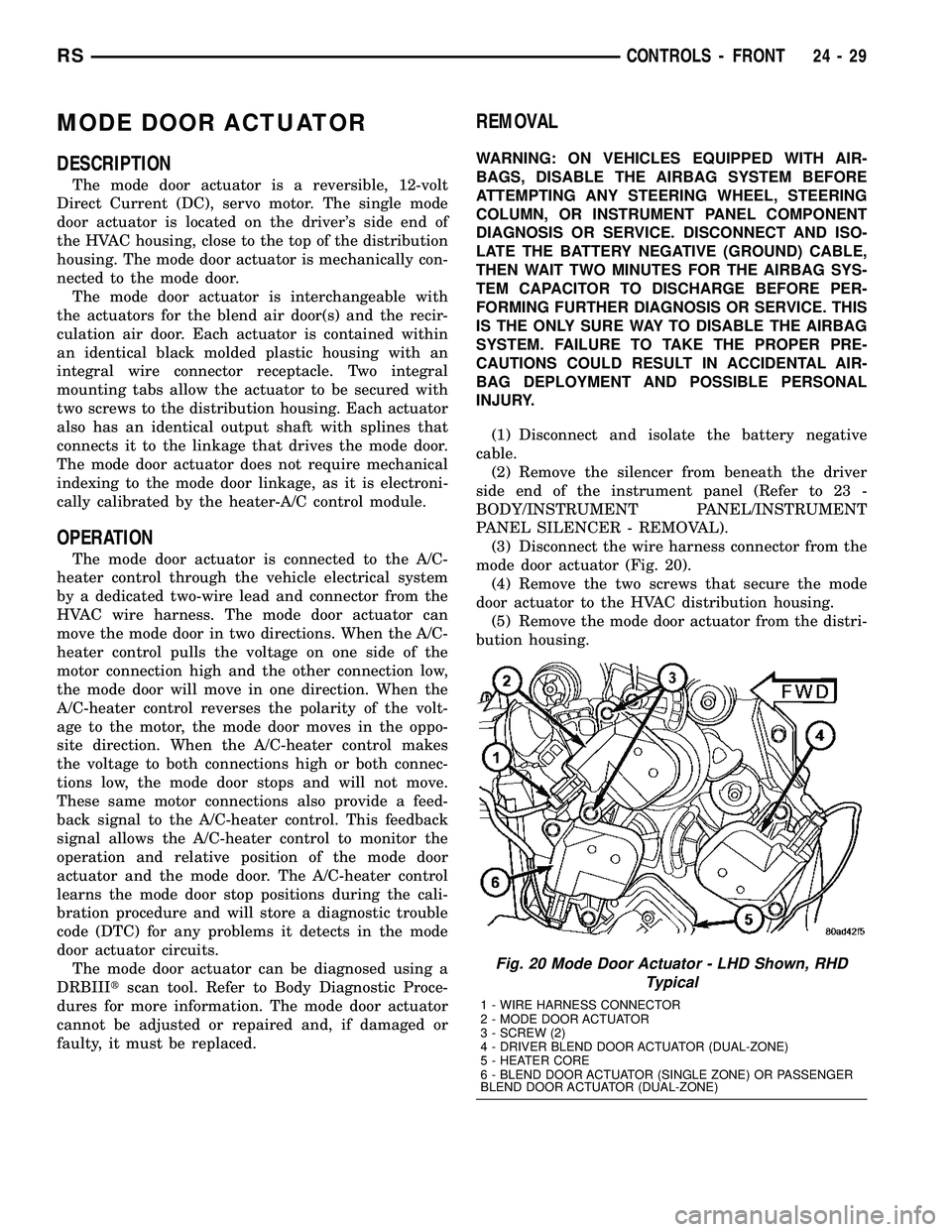
(3) Disconnect the wire harness connector from the
mode door actuator (Fig. 20).
(4) Remove the two screws that secure the mode
door actuator to the HVAC distribution housing.
(5) Remove the mode door actuator from the distri-
bution housing.
Fig. 20 Mode Door Actuator - LHD Shown, RHD
Typical
1 - WIRE HARNESS CONNECTOR
2 - MODE DOOR ACTUATOR
3 - SCREW (2)
4 - DRIVER BLEND DOOR ACTUATOR (DUAL-ZONE)
5 - HEATER CORE
6 - BLEND DOOR ACTUATOR (SINGLE ZONE) OR PASSENGER
BLEND DOOR ACTUATOR (DUAL-ZONE)
RSCONTROLS - FRONT24-29
Page 2182 of 2339
(1) Disconnect and isolate the negative battery
cable.
(2) Remove the glove box from the instrument
panel (Refer to 23 - BODY/INSTRUMENT PANEL/
GLOVE BOX - REMOVAL).
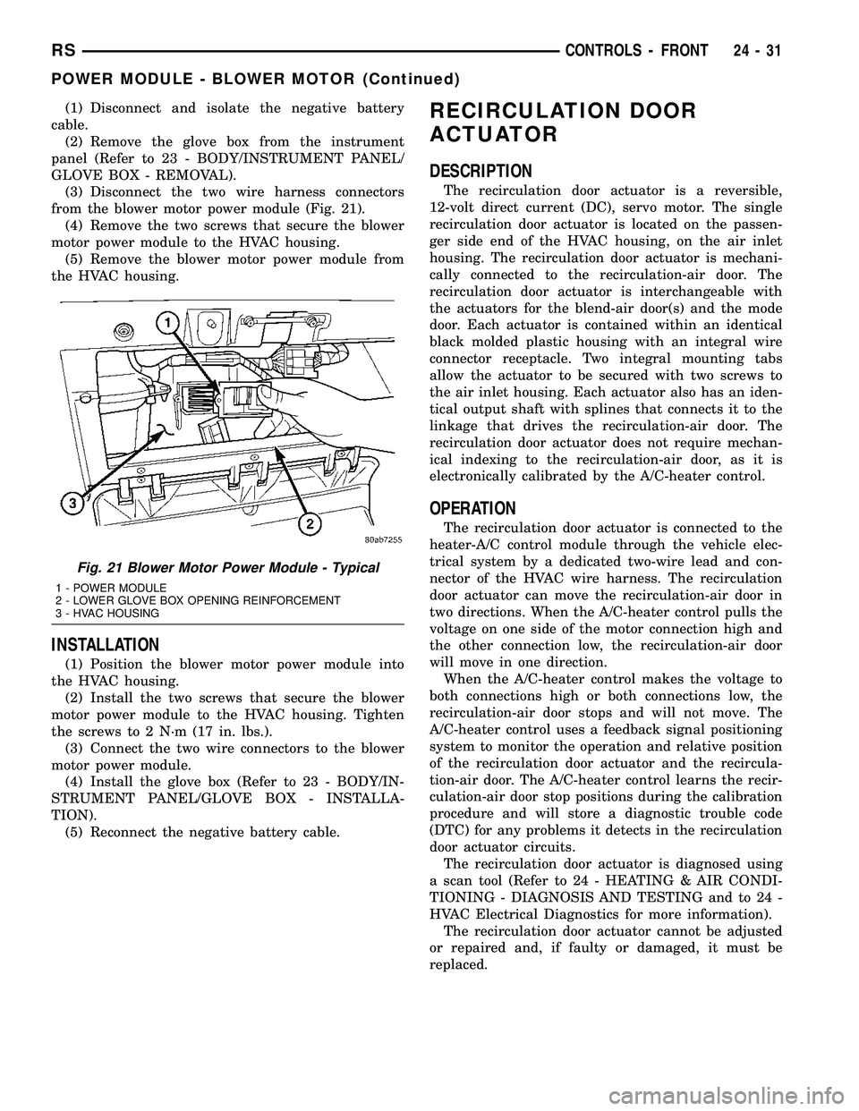
(3) Disconnect the two wire harness connectors
from the blower motor power module (Fig. 21).
(4) Remove the two screws that secure the blower
motor power module to the HVAC housing.
(5) Remove the blower motor power module from
the HVAC housing.
INSTALLATION
(1) Position the blower motor power module into
the HVAC housing.
(2) Install the two screws that secure the blower
motor power module to the HVAC housing. Tighten
the screws to 2 N´m (17 in. lbs.).
(3) Connect the two wire connectors to the blower
motor power module.
(4) Install the glove box (Refer to 23 - BODY/IN-
STRUMENT PANEL/GLOVE BOX - INSTALLA-
TION).
(5) Reconnect the negative battery cable.
RECIRCULATION DOOR
ACTUATOR
DESCRIPTION
The recirculation door actuator is a reversible,
12-volt direct current (DC), servo motor. The single
recirculation door actuator is located on the passen-
ger side end of the HVAC housing, on the air inlet
housing. The recirculation door actuator is mechani-
cally connected to the recirculation-air door. The
recirculation door actuator is interchangeable with
the actuators for the blend-air door(s) and the mode
door. Each actuator is contained within an identical
black molded plastic housing with an integral wire
connector receptacle. Two integral mounting tabs
allow the actuator to be secured with two screws to
the air inlet housing. Each actuator also has an iden-
tical output shaft with splines that connects it to the
linkage that drives the recirculation-air door. The
recirculation door actuator does not require mechan-
ical indexing to the recirculation-air door, as it is
electronically calibrated by the A/C-heater control.
OPERATION
The recirculation door actuator is connected to the
heater-A/C control module through the vehicle elec-
trical system by a dedicated two-wire lead and con-
nector of the HVAC wire harness. The recirculation
door actuator can move the recirculation-air door in
two directions. When the A/C-heater control pulls the
voltage on one side of the motor connection high and
the other connection low, the recirculation-air door
will move in one direction.
When the A/C-heater control makes the voltage to
both connections high or both connections low, the
recirculation-air door stops and will not move. The
A/C-heater control uses a feedback signal positioning
system to monitor the operation and relative position
of the recirculation door actuator and the recircula-
tion-air door. The A/C-heater control learns the recir-
culation-air door stop positions during the calibration
procedure and will store a diagnostic trouble code
(DTC) for any problems it detects in the recirculation
door actuator circuits.
The recirculation door actuator is diagnosed using
a scan tool (Refer to 24 - HEATING & AIR CONDI-
TIONING - DIAGNOSIS AND TESTING and to 24 -
HVAC Electrical Diagnostics for more information).
The recirculation door actuator cannot be adjusted
or repaired and, if faulty or damaged, it must be
replaced.
Fig. 21 Blower Motor Power Module - Typical
1 - POWER MODULE
2 - LOWER GLOVE BOX OPENING REINFORCEMENT
3 - HVAC HOUSING
RSCONTROLS - FRONT24-31
POWER MODULE - BLOWER MOTOR (Continued)
Page 2185 of 2339
INSTALLATION
(1) Position the rear A/C-heater control onto the
bezel or video screen housing, depending on applica-
tion.
(2) Install the three screws that secure the rear
A/C-heater control to the bezel or video screen hous-
ing. Tighten the screws to 2 N´m (17 in. lbs.).(3) If the rear A/C-heater control is to be mounted
into the headliner, position the rear A/C-heater con-
trol near the headliner and connect the wire harness
connector to the rear of the control.
(4) Insert the locator tabs on the back of the rear
control bezel over the forward edge of the headliner
opening.
(5) Slide the rear A/C-heater control bezel forward
far enough to align the snap clips on the bezel with
the receptacles on the headliner and by using hand
pressure, press the top edge of the bezel upward
until the two snap clips fully seat into their recepta-
cles.
(6) If the rear A/C-heater control is mounted to the
video screen housing, install the video screen to the
headliner (Refer to 8 - ELECTRICAL/AUDIO/VIDEO
SCREEN - INSTALLATION).
(7) Reconnect the negative battery cable.
(8) Using the DRB-IIItscan tool, reset the Rear
Temperature Selector calibration values.
(9) Verify that the Actuator Calibration of the
Front Control has passed. If an Actuator Calibration
has not passed correct any errors before proceeding
further.
(10) Rotate the Rear Temperature Selector counter
clockwise to the Cold Position, allow the Selector to
remain in the Cold Position for 5 seconds.
(11) Rotate the Rear Temperature Selector Clock-
wise to the Hot Position, allow the Selector to remain
in the Cold Position for 5 seconds.
(12) Calibration is now complete.
BLEND DOOR ACTUATOR
DESCRIPTION
The rear blend door actuator is a reversible,
12-volt Direct Current (DC), servo motor. The single
blend door actuator is located on the outboard side of
the rear HVAC housing, below the mode door actua-
tor. The blend door actuator is mechanically con-
nected to the blend air door.
The rear blend door actuator is interchangeable
with the actuator for the mode door. Each actuator is
contained within an identical black molded plastic
housing with an integral wire connector receptacle.
Two integral mounting tabs allow the actuator to be
secured with two screws to the rear HVAC housing.
Each actuator also has an identical output shaft with
splines that connects it to the pivot or linkage of the
proper door. The rear blend door actuator does not
require mechanical indexing to the blend air door
pivot, as it is electronically calibrated by the front
heater-A/C control module.
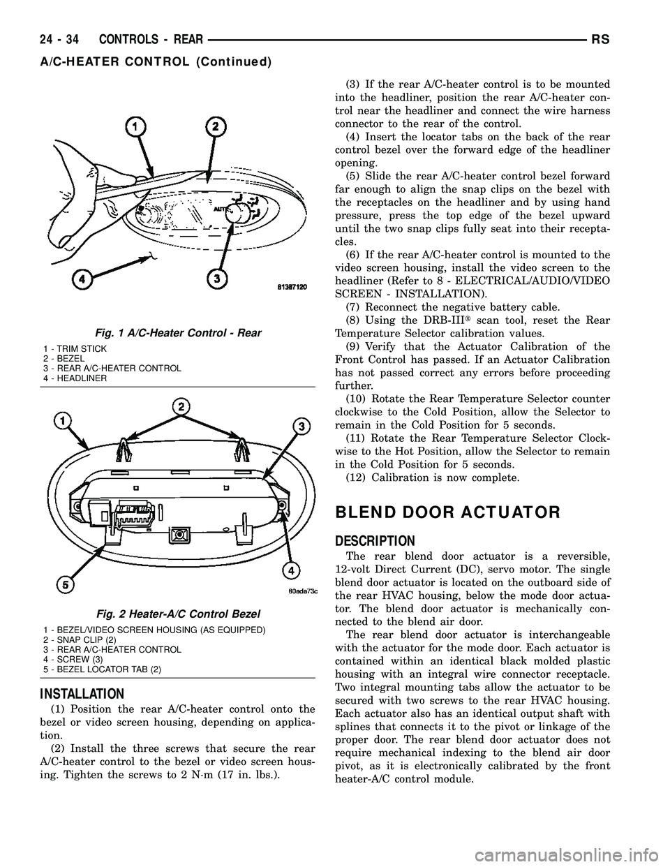
Fig. 1 A/C-Heater Control - Rear
1 - TRIM STICK
2 - BEZEL
3 - REAR A/C-HEATER CONTROL
4 - HEADLINER
Fig. 2 Heater-A/C Control Bezel
1 - BEZEL/VIDEO SCREEN HOUSING (AS EQUIPPED)
2 - SNAP CLIP (2)
3 - REAR A/C-HEATER CONTROL
4 - SCREW (3)
5 - BEZEL LOCATOR TAB (2)
24 - 34 CONTROLS - REARRS
A/C-HEATER CONTROL (Continued)
Page 2190 of 2339
INSTALLATION
(1) Position the rear blower motor resistor block
into the rear HVAC housing.
(2) Install the two screws that secure the rear
blower motor resistor block to the rear HVAC hous-
ing. Tighten the screws to 2 N´m (17 in. lbs.).
(3) Connect the rear HVAC wire harness connector
to the rear blower motor resistor block.
(4) Reinstall the right quarter trim panel and
right D-pillar trim panel onto the quarter inner
panel (Refer to 23 - BODY/INTERIOR/QUARTER
TRIM PANEL - INSTALLATION).
(5) Reconnect the battery negative cable.
MODE DOOR ACTUATOR -
REAR
DESCRIPTION
The rear mode door actuator is a reversible, 12-volt
Direct Current (DC), servo motor. The mode door
actuator is located on the outboard side of the rear
HVAC housing, above the blend door actuator. The
mode door actuator is mechanically connected to the
mode door.
The rear mode door actuator is interchangeable
with the actuator for the blend door. Each actuator is
contained within an identical black molded plastic
housing with an integral wire connector receptacle.
Two integral mounting tabs allow the actuator to be
secured with two screws to the rear HVAC housing.
Each actuator also has an identical output shaft with
splines that connects it to the pivot or linkage of the
proper door. The rear mode door actuator does not
require mechanical indexing to the mode door pivot,
as it is electronically calibrated by the front heater-
A/C control module.
OPERATION
The rear mode door actuator is connected to the
front heater-A/C control module through the vehicle
electrical system by a dedicated two-wire take out
and connector of the rear HVAC wire harness. The
rear mode door actuator can move the mode door in
two directions. When the front heater-A/C control
module pulls the voltage on one side of the motor
connection high and the other connection low, the
rear mode door will move in one direction. When themodule reverses the polarity of the voltage to the
motor, the rear mode door moves in the opposite
direction. When the module makes the voltage to
both connections high or both connections low, the
mode door stops and will not move. These same
motor connections also provide a feedback signal to
the front heater-A/C control module. This feedback
signal allows the module to monitor the operation
and relative positions of the rear mode door actuator
and the mode door. The front heater-A/C control mod-
ule learns the rear mode door stop positions during
the calibration procedure and will store a Diagnostic
Trouble Code (DTC) for any problems it detects in
the mode door actuator circuits.
The rear mode door actuator can be diagnosed
using a DRBIIItscan tool. Refer to Body Diagnostic
Procedures for more information. The rear mode door
actuator cannot be adjusted or repaired and, if dam-
aged or faulty, it must be replaced.
REMOVAL
(1) Disconnect and isolate the battery negative
cable.
(2) Remove the right quarter trim panel and right
D-pillar trim panel from the quarter inner panel
(Refer to 23 - BODY/INTERIOR/QUARTER TRIM
PANEL - REMOVAL).
(3) Remove the two screws that secure the top of
the quarter trim panel attaching bracket to the quar-
ter inner panel.
(4) Remove the screw that secures the back of the
rear HVAC housing to the right D-pillar.
(5) Remove the screw that secures the front of the
rear HVAC housing to the right quarter inner panel.
(6) Carefully pull the top of the rear HVAC hous-
ing away from the right quarter inner panel far
enough to reach between the rear HVAC housing and
the quarter inner panel to access the rear mode door
actuator (Fig. 7).
(7) Remove the two screws that secure the mode
door actuator to the rear HVAC housing.
(8) Pull the mode door actuator away from the
rear HVAC housing far enough to disengage the
actuator output shaft from the mode door linkage.
(9) Raise the mode door actuator far enough to
access and disconnect the rear HVAC wire harness
connector from the actuator
RSCONTROLS - REAR24-39
BLOWER MOTOR RESISTOR BLOCK (Continued)
Page 2243 of 2339
(7) Lubricate a new rubber O-ring seal with clean
refrigerant oil and install it on the liquid line fitting.
(8) Reconnect the A/C liquid line to the receiver/
drier.
(9) Install the bolt that secures the A/C liquid line
to the receiver/drier. Tighten the bolt to 11 N´m (97
in. lbs.).
(10) If equipped, reinstall the A/C ground strap
eyelet terminal connector onto the weld stud on the
top of the right front strut tower (if equipped).
(11) If equipped, install the nut that secures the
A/C ground strap to the weld stud. Tighten the nut
to 12 N´m (106 in. lbs.)
(12) Install the A/C pressure transducer (Refer to
24 - HEATING & AIR CONDITIONING/CONTROLS
- FRONT/A/C PRESSURE TRANSDUCER - INSTAL-
LATION).
(13) Connect the drain tube to the wiper module
drain on the right side of the engine compartment.
(14) Install the air cleaner housing into the right
side of the engine compartment.
(15) On RHD models, install the liquid line into
the retaining bracket located at the top of the dash
panel.
(16) If the vehicle is equipped with the optional
rear heating-A/C system, go to Step 17. If the vehicle
does not have the optional rear heating-A/C system,
go to Step 23.
(17) Raise and support the vehicle.
(18) Remove the tape or plugs from the A/C liquid
line extension fitting and the underbody liquid line
fitting.
(19) Lubricate a new rubber O-ring seal with clean
refrigerant oil and install it on the underbody liquid
line fitting.
(20) Connect the A/C liquid line extension fitting
to the underbody liquid line fitting. Tighten the fit-
tings to 23 N´m (17 ft. lbs.).
(21) Install a new tie strap just forward of the con-
nections between the underbody plumbing and the
engine compartment plumbing for the rear heating-
A/C system.
(22) Lower the vehicle.
(23) Reconnect the negative battery cable.
(24) Evacuate the refrigerant system (Refer to 24 -
HEATING & AIR CONDITIONING/PLUMBING -
FRONT/REFRIGERANT - STANDARD PROCE-
DURE - REFRIGERANT SYSTEM EVACUATE).
(25) Charge the refrigerant system (Refer to 24 -
HEATING & AIR CONDITIONING/PLUMBING -
FRONT/REFRIGERANT - STANDARD PROCE-
DURE - REFRIGERANT SYSTEM CHARGE).RECEIVER / DRIER
DESCRIPTION
The receiver/drier is mounted in a bracket secured
to the right front strut tower in the engine compart-
ment. The receiver/drier is connected between the
front and rear sections of the liquid line between the
condenser outlet and the evaporator inlet. The receiv-
er/drier cannot be repaired. If the receiver/drier is
faulty or damaged, or if the refrigerant system has
been contaminated or left open to the atmosphere for
an indeterminable period or if the A/C compressor
has failed, it must be replaced.
OPERATION
The receiver/drier performs a filtering action to
prevent foreign material in the refrigerant from con-
taminating the expansion valve. Desiccant inside the
receiver/drier canister absorbs any moisture which
may have entered and become trapped within the
refrigerant system. In addition, during periods of
high demand air conditioner operation, the receiver/
drier acts as a reservoir to store surplus refrigerant.
Refrigerant enters the receiver/drier as a high-pres-
sure, low temperature liquid.
REMOVAL
WARNING: REFER TO THE APPLICABLE WARN-
INGS AND CAUTIONS FOR THIS SYSTEM BEFORE
PERFORMING THE FOLLOWING OPERATION (Refer
to 24 - HEATING & AIR CONDITIONING/PLUMBING -
FRONT - WARNING - A/C PLUMBING) and (Refer to
24 - HEATING & AIR CONDITIONING/PLUMBING -
FRONT - CAUTION - A/C PLUMBING).
(1) Recover the refrigerant from the refrigerant
system (Refer to 24 - HEATING & AIR CONDITION-
ING/PLUMBING - FRONT/REFRIGERANT - STAN-
DARD PROCEDURE - REFRIGERANT
RECOVERY).
(2) Remove the air cleaner housing from the right
side of the engine compartment.
(3) Remove the bolt that secures the liquid line
front section fitting to the top of the receiver/drier
(Fig. 30).
(4) Disconnect the liquid line fitting from the
receiver/drier inlet port.
(5) Remove the O-ring seal from the liquid line fit-
ting and discard.
(6) Install plugs in, or tape over the opened liquid
line fitting and the receiver/drier inlet port.
24 - 92 PLUMBING - FRONTRS
LIQUID LINE (Continued)
Page 2310 of 2339
COVER - RIGHT - INSTALLATION,CYLINDER HEAD ..................... 9-106
COVER - RIGHT - REMOVAL, CYLINDER HEAD .............................. 9-106
COVER/FOAM - SECOND ROW - FOLD-IN-FLOOR - INSTALLATION, SEAT
BACK ............................. 23-133
COVER/FOAM - SECOND ROW - FOLD-IN-FLOOR - REMOVAL, SEAT
BACK ............................. 23-133
COVER/FOAM - THIRD ROW - FOLD-IN-FLOOR - INSTALLATION, SEAT
BACK ............................. 23-156
COVER/FOAM - THIRD ROW - FOLD-IN-FLOOR - INSTALLATION, SEAT
CUSHION .......................... 23-159
COVER/FOAM - THIRD ROW - FOLD-IN-FLOOR - REMOVAL, SEAT
BACK ............................. 23-155
COVER/FOAM - THIRD ROW - FOLD-IN-FLOOR - REMOVAL, SEAT
CUSHION .......................... 23-159
COVER/FOAM -SECOND ROW - FOLD-IN-FLOOR - INSTALLATION, SEAT
CUSHION .......................... 23-136
COVER/FOAM -SECOND ROW - FOLD-IN-FLOOR - REMOVAL, SEAT
CUSHION .......................... 23-136
COVER(S) - DESCRIPTION, CYLINDER HEAD .............................. 9-105
COVER(S) - INSTALLATION, TIMING BELT ............................... 9-64
COVERS - QUAD BUCKET, 50/50 SPLIT, BENCH - INSTALLATION, SEAT BACK
HINGE ............................ 23-146
COVERS - QUAD BUCKET, 50/50 SPLIT, BENCH - REMOVAL, SEAT BACK HINGE. . . 23-146
COVER(S) - REMOVAL, TIMING BELT ......9-63
COWL GRILLE - INSTALLATION .........23-50
COWL GRILLE - REMOVAL .............23-50
COWL TRIM - INSTALLATION ...........23-88
COWL TRIM - REMOVAL ...............23-88
C-PILLAR - INSTALLATION, SEAT BELT HEIGHT ADJUSTE R-BOR............. 8O-38
C-PILLAR - REMOVAL, SEAT BELT HEIGHT ADJUSTE R-BOR............. 8O-38
C-PILLAR TRIM - INSTALLATION ........23-88
C-PILLAR TRIM - REMOVAL ............23-88
CRADLE CROSSMEMBER - DESCRIPTION, FRONT .................13-14
CRADLE CROSSMEMBER THREAD REPAIR - DESCRIPTION, FRONT .........13-14
CRANK - INSTALLATION, WINDOW .......23-21
CRANK - REMOVAL, WINDOW ..........23-21
CRANKSHAFT - INSPECTION .............9-38
CRANKSHAFT - INSTALLATION ...........9-39
CRANKSHAFT - REMOVAL ..............9-37
CRANKSHAFT END PLAY - STANDARD PROCEDURE ......................... 9-37
CRANKSHAFT END PLAY - STANDARD PROCEDURE, MEASURING .............9-128
CRANKSHAFT MAIN BEARINGS - INSTALLATION ....................... 9-127
CRANKSHAFT MAIN BEARINGS - REMOVAL .......................... 9-127
CRANKSHAFT OIL SEAL - FRONT - INSTALLATION ................... 9-130,9-42
CRANKSHAFT OIL SEAL - FRONT - REMOVAL ...................... 9-130,9-41
CRANKSHAFT OIL SEAL - REAR - INSTALLATION ................... 9-131,9-42
CRANKSHAFT OIL SEAL - REAR - REMOVAL ...................... 9-131,9-42
CRANKSHAFT POSITION SENSOR - DESCRIPTION ....................... 14-29
CRANKSHAFT POSITION SENSOR - OPERATION ......................... 14-29
CRANKSHAFT POSITION SENSOR - REMOVAL .......................... 14-30
CRANKSHAFT REAR OIL SEAL RETAINER - INSTALLATION ..................... 9-132
CRANKSHAFT REAR OIL SEAL RETAINER - REMOVAL ......................... 9-132
CRANKSHAFT SPROCKET - INSTALLATION ................... 9-160,9-67
CRANKSHAFT SPROCKET - REMOVAL ....9-159,
9-66 CROSSBAR - INSTALLATION, LUGGAGE
RACK .............................. 23-59
CROSSBAR - REMOVAL, LUGGAGE RACK . 23-58
CROSSMEMBER - DESCRIPTION, FRONT CRADLE ............................ 13-14
CROSSMEMBER - INSTALLATION, UPPER RADIATOR .................... 23-56
CROSSMEMBER - REMOVAL, UPPER RADIATOR .......................... 23-56
CROSSMEMBER MOUNT BUSHINGS - INSTALLATION, FRONT ................13-17
CROSSMEMBER MOUNT BUSHINGS - REMOVAL, FRONT .................... 13-17
CROSSMEMBER THREAD REPAIR - DESCRIPTION, FRONT CRADLE .........13-14
CROSS-OVER PIPE - 3.3/3.8L - INSTALLATION ........................ 11-6
CROSS-OVER PIPE - 3.3/3.8L - REMOVAL ........................... 11-6
CUP HOLDER - FOLD-IN-FLOOR - INSTALLATION, SIDE SHIELD ..........23-160
CUP HOLDER - FOLD-IN-FLOOR - REMOVAL, SIDE SHIELD ..............23-160
CUP HOLDER - INSTALLATION ..........23-65
CUP HOLDER - INSTALLATION, QUAD BUCKET SEAT SIDE SHIELD - NO .......23-143
CUP HOLDER - REMOVAL ..............23-65
CUP HOLDER - REMOVAL, QUAD BUCKET SEAT SIDE SHIELD - NO .......23-143
CURB HEIGHT MEASUREMENT - STANDARD PROCEDURE ................2-55
CURTAIN AIRBAG - DESCRIPTION .......8O-12
CURTAIN AIRBAG - INSTALLATION .......8O-16
CURTAIN AIRBAG - OPERATION .........8O-13
CURTAIN AIRBAG - REMOVAL ..........8O-14
CUSHION - INSTALLATION, FRONT SEAT . 23-118
CUSHION - INSTALLATION, QUAD SEAT . . 23-141
CUSHION - INSTALLATION, STABILIZER BAR.................................2-4
CUSHION - OCS - INSTALLATION, FRONT SEAT ............................. 23-120
CUSHION - OCS - REMOVAL, FRONT SEAT ............................. 23-119
CUSHION - REMOVAL, FRONT SEAT .....23-117
CUSHION - REMOVAL, QUAD SEAT .....23-141
CUSHION - REMOVAL, STABILIZER BAR ....2-4
CUSHION COVER - QUAD BUCKET, 50/50 SPLIT, BENCH - INSTALLATION, SEAT . . . 23-144
CUSHION COVER - QUAD BUCKET, 50/50 SPLIT, BENCH - REMOVAL, SEAT .......23-144
CUSHION COVER/FOAM - THIRD ROW - FOLD-IN-FLOOR - INSTALLATION, SEAT . . 23-159
CUSHION COVER/FOAM - THIRD ROW - FOLD-IN-FLOOR - REMOVAL, SEAT ......23-159
CUSHION COVER/FOAM -SECOND ROW - FOLD-IN-FLOOR - INSTALLATION, SEAT . . 23-136
CUSHION COVER/FOAM -SECOND ROW - FOLD-IN-FLOOR - REMOVAL, SEAT ......23-136
CUSHION PAN PANEL-THIRD ROW - FOLD-IN-FLOOR - INSTALLATION,
BOTTOM OF SEAT ................... 23-152
CUSHION PAN PANEL-THIRD ROW - FOLD-IN-FLOOR - REMOVAL, BOTTOM
OF SEAT........................... 23-152
CUSHION SIDE COVER - INSTALLATION, FRONT SEAT ....................... 23-121
CUSHION SIDE COVER - OCS - INSTALLATION, FRONT SEAT ..........23-122
CUSHION SIDE COVER - OCS - REMOVAL, FRONT SEAT ..............23-121
CUSHION SIDE COVER - REMOVAL, FRONT SEAT ....................... 23-120
CUSHION SIDE SHIELD - SECOND ROW - FOLD-IN-FLOOR - INSTALLATION,
SEAT ............................. 23-138
CUSHION SIDE SHIELD - SECOND ROW - FOLD-IN-FLOOR - REMOVAL, SEAT ....23-138
CV BOOT - INNER - INSTALLATION ........3-7
CV BOOT - INNER - REMOVAL ............3-6
CV BOOT - OUTER - INSTALLATION .......3-11
CV BOOT - OUTER - REMOVAL ...........3-10
CYCLE, STANDARD PROCEDURE - POWER LIFTGATE LEARN ...............8N-8
CYCLE, STANDARD PROCEDURE - POWER SLIDING DOOR LEARN .........8N-48
CYLINDER - DESCRIPTION, KEY/LOCK ....19-20
CYLINDER - DESCRIPTION, STANDARD 4 . . . 8I-9
CYLINDER - INSTALLATION, KEY/LOCK . . . 19-20CYLINDER - INSTALLATION, LOCK . . 23-19,23-42
CYLINDER - INSTALLATION, SUPPORT
....23-43
CYLINDER - OPERATION, KEY/LOCK ......19-20
CYLINDER - REMOVAL, KEY/LOCK .......19-20
CYLINDER - REMOVAL, LOCK ......23-19,23-42
CYLINDER - REMOVAL, SUPPORT .......23-42
CYLINDER BLEEDING - STANDARD PROCEDURE, MASTER .................5-36
CYLINDER BORE FITTING - STANDARD PROCEDURE, PISTON TO ...............9-44
CYLINDER BORE HONING - STANDARD PROCEDURE .................... 9-115,9-36
CYLINDER COMBUSTION PRESSURE LEAKAGE TEST - DIAGNOSIS AND
TESTING ......................... 9-85,9-9
CYLINDER COMPRESSION PRESSURE TEST - DIAGNOSIS AND TESTING .....9-85,9-9
CYLINDER (FLUID RESERVOIR) - ASSEMBLY, MASTER ................... 5-39
CYLINDER (FLUID RESERVOIR) - DISASSEMBLY, MASTER ................5-38
CYLINDER HEAD - CLEANING .......9-103,9-26
CYLINDER HEAD - DESCRIPTION ....9-102,9-25
CYLINDER HEAD - INSPECTION .....9-104,9-27
CYLINDER HEAD - INSTALLATION . . . 9-104,9-27
CYLINDER HEAD - REMOVAL .......9-103,9-26
CYLINDER HEAD COVER - CLEANING ......9-31
CYLINDER HEAD COVER - INSPECTION ....9-31
CYLINDER HEAD COVER - INSTALLATION ......................... 9-32
CYLINDER HEAD COVER - LEFT - INSTALLATION ....................... 9-107
CYLINDER HEAD COVER - LEFT - REMOVAL .......................... 9-107
CYLINDER HEAD COVER - REMOVAL ......9-31
CYLINDER HEAD COVER - RIGHT - INSTALLATION ....................... 9-106
CYLINDER HEAD COVER - RIGHT - REMOVAL .......................... 9-106
CYLINDER HEAD COVER(S) - DESCRIPTION ....................... 9-105
CYLINDER HEAD GASKET - DIAGNOSIS AND TESTING ................... 9-102,9-25
CYLINDER HEAD OFF - INSTALLATION . . . 9-111, 9-33
CYLINDER HEAD OFF - REMOVAL . . . 9-109,9-33
CYLINDER HEAD ON - INSTALLATION ....9-111,
9-33
CYLINDER HEAD ON - REMOVAL ....9-111,9-33
CYLINDER LOCK SWITCH - EXPORT - DESCRIPTION, DOOR .................8N-22
CYLINDER LOCK SWITCH - EXPORT - OPERATION, DOOR ................... 8N-22
CYLINDER LOCK SWITCH, EXPORT - DOOR ............................. 8N-22
CYLINDERS - INSPECTION, WHEEL .......5-62
CYLINDERS - INSTALLATION, WHEEL .....5-62
CYLINDERS - REMOVAL, WHEEL .........5-62
DAMAGED OR WORN THREADS - STANDARD PROCEDURE, REPAIR OF . . 9-10,9-88
DAMPER - INSTALLATION, VIBRATION . . . 9-132, 9-49
DAMPER - REMOVAL, VIBRATION . . . 9-132,9-48
DATA BUS COMMUNICATION RECEIVE - PCM INPUT - OPERATION ..............8E-14
DATA LINK CONNECTOR - DESCRIPTION . . . 8E-6
DATA LINK CONNECTOR - OPERATION .....8E-6
DAY / NIGHT MIRROR - DESCRIPTION, AUTOMATIC ........................ 8N-28
DAY / NIGHT MIRROR - OPERATION, AUTOMATIC ........................ 8N-28
DAY / NIGHT MIRROR, DIAGNOSIS AND TESTING - AUTOMATIC ................8N-28
DEAERATION - DIAGNOSIS AND TESTING, COOLING SYSTEM .............7-4
DECOUPLER PULLEY - DESCRIPTION, GENERATOR ........................ 8F-28
DECOUPLER PULLEY - DIAGNOSIS AND TESTING, GENERATOR ................8F-28
DECOUPLER PULLEY - INSTALLATION, GENERATOR ........................ 8F-29
DECOUPLER PULLEY - OPERATION, GENERATOR ........................ 8F-28
DECOUPLER PULLEY - REMOVAL, GENERATOR ........................ 8F-29
DEFINITION, DESCRIPTION - TRIP ........25-1
DEFLECTOR - INSTALLATION, WIND .....23-174
DEFLECTOR - REMOVAL, WIND ........23-174
RS INDEX9
Description Group-Page Description Group-Page Description Group-Page
Page 2321 of 2339

LWB - INSTALLATION, SEAT BELT &RETRACTOR - SECOND ROW - RIGHT
OUTBOARD WITH REAR HVAC ..........8O-41
LWB - REMOVAL, SEAT BELT & RETRACTOR - SECOND ROW - RIGHT
OUTBOARD WITH REAR HVAC ..........8O-41
MACHINING - STANDARD PROCEDURE, BRAKE ROTOR ....................... 5-58
MAIN BEARING FITTING - STANDARD PROCEDURE ........................ 9-125
MAIN BEARINGS - INSTALLATION, CRANKSHAFT ....................... 9-127
MAIN BEARINGS - REMOVAL, CRANKSHAFT ....................... 9-127
MANAGER - DESCRIPTION, TASK ........25-25
MANAGER - OPERATION, TASK .........25-25
MANIFOLD - CLEANING, EXHAUST ........9-63
MANIFOLD - DESCRIPTION, INTAKE . . 9-147,9-60
MANIFOLD - INSPECTION, EXHAUST ......9-63
MANIFOLD - INSTALLATION, EXHAUST ....9-63
MANIFOLD - INSTALLATION, LOWER INTAKE ............................ 9-151
MANIFOLD - INSTALLATION, UPPER INTAKE ............................ 9-149
MANIFOLD - LEFT - CLEANING, EXHAUST ........................... 9-154
MANIFOLD - LEFT - INSPECTION, EXHAUST ........................... 9-155
MANIFOLD - LEFT - INSTALLATION, EXHAUST ........................... 9-155
MANIFOLD - LEFT - REMOVAL, EXHAUST . 9-154
MANIFOLD - LOWER - CLEANING, INTAKE ............................ 9-151
MANIFOLD - LOWER - INSPECTION, INTAKE ........................ 9-151,9-62
MANIFOLD - LOWER - INSTALLATION, INTAKE ............................. 9-62
MANIFOLD - LOWER - REMOVAL, INTAKE ............................. 9-62
MANIFOLD - REMOVAL, EXHAUST ........9-63
MANIFOLD - REMOVAL, LOWER INTAKE . . 9-150
MANIFOLD - REMOVAL, UPPER INTAKE . . . 9-148
MANIFOLD - RIGHT - CLEANING, EXHAUST ........................... 9-153
MANIFOLD - RIGHT - INSPECTION, EXHAUST ........................... 9-153
MANIFOLD - RIGHT - INSTALLATION, EXHAUST ........................... 9-153
MANIFOLD - RIGHT - REMOVAL, EXHAUST ........................... 9-152
MANIFOLD - UPPER - INSPECTION, INTAKE ............................. 9-61
MANIFOLD - UPPER - INSTALLATION, INTAKE ............................. 9-61
MANIFOLD - UPPER - REMOVAL, INTAKE . . 9-60
MANIFOLD LEAKS - DIAGNOSIS AND TESTING, INTAKE ................ 9-147,9-60
MANIFOLD STRIPPED THREAD REPAIR - STANDARD PROCEDURE ...............9-147
MANIFOLD VACUUM PORT REPAIR - STANDARD PROCEDURE, INTAKE ........9-148
MANUAL - INSTALLATION, WINDOW REGULATOR ........................ 23-23
MANUAL - OCS - INSTALLATION, FRONT SEAT RISER ........................ 23-123
MANUAL - OCS - REMOVAL, FRONT SEAT RISER ........................ 23-123
MANUAL - REMOVAL, WINDOW REGULATOR ........................ 23-22
MANUAL ADJUSTER - INSTALLATION, FRONT SEAT TRACK .................23-126
MANUAL ADJUSTER - REMOVAL, FRONT SEAT TRACK ....................... 23-125
MANUAL DUAL ZONE, DESCRIPTION ......24-2
MANUAL DUAL ZONE, OPERATION ........24-5
MANUAL SINGLE ZONE, DESCRIPTION ....24-2
MANUAL SINGLE ZONE, OPERATION ......24-4
MANUAL TEMPERATURE CONTROL SYSTEM, OPERATION ................24-113
MANUAL THREE ZONE, DESCRIPTION .....24-2
MANUAL THREE ZONE, OPERATION .......24-5
MAP SENSOR - DESCRIPTION ..........14-34
MAP SENSOR - OPERATION ............14-34
MASTER CYLINDER BLEEDING - STANDARD PROCEDURE ................5-36
MASTER CYLINDER (FLUID RESERVOIR) - ASSEMBLY ......................... 5-39MASTER CYLINDER (FLUID RESERVOIR)
- DISASSEMBLY ...................... 5-38
MATCH MOUNTING - STANDARD PROCEDURE, TIRE AND WHEEL ..........22-7
MATS - INSTALLATION, CARPETS AND FLOOR ............................. 23-81
MATS - REMOVAL, CARPETS AND FLOOR ............................. 23-81
MEASUREMENT - STANDARD PROCEDURE, CURB HEIGHT .............2-55
MEASUREMENT AND ADJUSTMENT, ADJUSTMENTS - DIFFERENTIAL
BEARING PRELOAD ................... 21-79
MEASUREMENTS - SPECIFICATIONS, GAP AND FLUSH .................... 23-177
MEASURING BEARING CLEARANCE USING PLASTIGAGE - STANDARD
PROCEDURE ..................... 9-12,9-86
MEASURING CAMSHAFT END PLAY - STANDARD PROCEDURE ................9-29
MEASURING CONNECTING ROD BEARING CLEARANCE - STANDARD
PROCEDURE ........................ 9-123
MEASURING CRANKSHAFT END PLAY - STANDARD PROCEDURE ...............9-128
MEASURING TIMING CHAIN WEAR - STANDARD PROCEDURE ...............9-155
MECHANICAL - DIAGNOSIS AND TESTING, ENGINE DIAGNOSIS ........9-6,9-82
MECHANISM -SECOND ROW -FOLD-IN- FLOOR - INSTALLATION, SEAT
RECLINER/FORWARD FOLDING ........23-137
MECHANISM -SECOND ROW -FOLD-IN- FLOOR - REMOVAL, SEAT RECLINER/
FORWARD FOLDING .................23-137
MECHANISM -THIRD ROW -FOLD-IN- FLOOR - INSTALLATION, SEAT
RECLINER/FOLD FORWARD ...........23-160
MECHANISM -THIRD ROW -FOLD-IN- FLOOR - REMOVAL, SEAT RECLINER/
FOLD FORWARD .................... 23-160
MEMORIES, OPERATION - FUEL CORRECTION OR ADAPTIVE ............14-24
MEMORY SEAT/MIRROR MODULE - DESCRIPTION ........................ 8E-9
MEMORY SEAT/MIRROR MODULE - OPERATION .......................... 8E-9
MEMORY SEAT/MIRROR MODULE, DIAGNOSIS AND TESTING ..............8E-9
MEMORY SWITCH - DESCRIPTION ......8N-36
MEMORY SWITCH - OPERATION ........8N-36
MEMORY SWITCH, DIAGNOSIS AND TESTING ........................... 8N-37
MEMORY SYSTEM, DESCRIPTION .......8N-32
MEMORY SYSTEM, DIAGNOSIS AND TESTING ........................... 8N-33
MEMORY SYSTEM, OPERATION .........8N-33
MESSAGE CENTER - INSTALLATION ......8M-1
MESSAGE CENTER - REMOVAL ..........8M-1
MICRO 420 BATTERY TESTER, STANDARD PROCEDURE ...............8F-15
MINI-TRIP COMPUTER, DIAGNOSIS AND TESTING - COMPASS .................8M-10
MIRROR - DESCRIPTION, AUTOMATIC DAY / NIGHT ........................ 8N-28
MIRROR - INSTALLATION, GLASS- OUTSIDE REARVIEW .................. 23-61
MIRROR - INSTALLATION, REAR VIEW . . . 23-97
MIRROR - INSTALLATION, SIDE VIEW ....23-60
MIRROR - OPERATION, AUTOMATIC DAY / NIGHT ............................ 8N-28
MIRROR - REMOVAL, GLASS-OUTSIDE REARVIEW .......................... 23-61
MIRROR - REMOVAL, REAR VIEW .......23-97
MIRROR - REMOVAL, SIDE VIEW ........23-60
MIRROR - REMOVAL, SIDEVIEW ........8N-30
MIRROR, DIAGNOSIS AND TESTING - AUTOMATIC DAY / NIGHT ..............8N-28
MIRROR SWITCH - EXPORT - DESCRIPTION, POWER FOLDAWAY ......8N-29
MIRROR SWITCH - EXPORT - INSTALLATION, POWER FOLDAWAY ......8N-30
MIRROR SWITCH - EXPORT - OPERATION, POWER FOLDAWAY ........8N-29
MIRROR SWITCH - EXPORT - REMOVAL, POWER FOLDAWAY .................. 8N-29
MIRRORS - DESCRIPTION, HEATED .......8G-6
MIRRORS - DESCRIPTION, POWER ......8N-26 MIRRORS - OPERATION, HEATED
........8G-6
MIRRORS - OPERATION, POWER ........8N-26
MIRRORS, DIAGNOSIS AND TESTING - POWER ............................ 8N-27
MODE DOOR ACTUATOR - DESCRIPTION . . 24-29
MODE DOOR ACTUATOR - INSTALLATION ....................... 24-30
MODE DOOR ACTUATOR - OPERATION . . . 24-29
MODE DOOR ACTUATOR - REAR - DESCRIPTION ....................... 24-39
MODE DOOR ACTUATOR - REAR - INSTALLATION ....................... 24-40
MODE DOOR ACTUATOR - REAR - OPERATION ......................... 24-39
MODE DOOR ACTUATOR - REAR - REMOVAL .......................... 24-39
MODE DOOR ACTUATOR - REMOVAL .....24-29
MODE, OPERATION - DRB III TS TAT E
DISPLAY TEST ....................... 25-10
MODELS, INSTALLATION - RG ..........24-27
MODELS, INSTALLATION - RS ..........24-28
MODELS, REMOVAL - RG ..............24-27
MODELS, REMOVAL - RS ..............24-27
MODES OF OPERATION - OPERATION ....14-22
MODULE - BLOWER MOTOR - DESCRIPTION, POWER ................24-30
MODULE - BLOWER MOTOR - INSTALLATION, POWER ...............24-31
MODULE - BLOWER MOTOR - OPERATION, POWER .................. 24-30
MODULE - BLOWER MOTOR - REMOVAL, POWER ................... 24-30
MODULE - DESCRIPTION, BODY CONTROL ........................... 8E-2
MODULE - DESCRIPTION, FRONT CONTROL ........................... 8E-7
MODULE - DESCRIPTION, FUEL PUMP ....14-8
MODULE - DESCRIPTION, HEATED SEAT . . . 8E-8
MODULE - DESCRIPTION, INTEGRATED POWER ..........................8W -97-1
MODULE - DESCRIPTION, MEMORY SEAT/MIRROR ........................ 8E-9
MODULE - DESCRIPTION, OCCUPANT CLASSIFICATION ..................... 8O-25
MODULE - DESCRIPTION, PARK ASSIST . . . 8B-4
MODULE - DESCRIPTION, POWER LIFTGATE CONTROL .................. 8E-10
MODULE - DESCRIPTION, SENTRY KEY REMOTE ENTRY ...................... 8Q-3
MODULE - DESCRIPTION, SLIDING DOOR CONTROL ..................... 8E-18
MODULE - DIAGNOSIS AND TESTING, SENTRY KEY REMOTE ENTRY ...........8Q-5
MODULE - EXPORT - DESCRIPTION, ANTENNA .......................... 8A-10
MODULE - EXPORT - OPERATION, ANTENNA .......................... 8A-10
MODULE - INSTALLATION, BODY CONTROL ........................... 8E-4
MODULE - INSTALLATION, HANDS FREE . . . 8T-3
MODULE - INSTALLATION, INTEGRATED POWER ..........................8W -97-2
MODULE - INSTALLATION, OCCUPANT CLASSIFICATION ..................... 8O-26
MODULE - INSTALLATION, PARK ASSIST . . 8B-6
MODULE - INSTALLATION, SENTRY KEY REMOTE ENTRY ...................... 8Q-6
MODULE - INSTALLATION, WIPER .......8R-14
MODULE - OPERATION, BODY CONTROL . . . 8E-3
MODULE - OPERATION, FRONT CONTROL ........................... 8E-7
MODULE - OPERATION, FUEL PUMP ......14-9
MODULE - OPERATION, HEATED SEAT .....8E-8
MODULE - OPERATION, INTEGRATED POWER ..........................8W -97-2
MODULE - OPERATION, MEMORY SEAT/MIRROR ........................ 8E-9
MODULE - OPERATION, OCCUPANT CLASSIFICATION ..................... 8O-25
MODULE - OPERATION, PARK ASSIST .....8B-5
MODULE - OPERATION, POWER LIFTGATE CONTROL .................. 8E-10
MODULE - OPERATION, SENTRY KEY REMOTE ENTRY ...................... 8Q-4
MODULE - OPERATION, SLIDING DOOR CONTROL .......................... 8E-18
MODULE - REAR BLOWER MOTOR - DESCRIPTION, POWER ................24-40
20 INDEXRS
Description Group-Page Description Group-Page Description Group-Page
Page 2327 of 2339
RELIEF VALVE, OPERATION - HIGHPRESSURE ......................... 24-72
REMOTE ENTRY MODULE - DESCRIPTION, SENTRY KEY .............8Q-3
REMOTE ENTRY MODULE - DIAGNOSIS AND TESTING, SENTRY KEY .............8Q-5
REMOTE ENTRY MODULE - INSTALLATION, SENTRY KEY ............8Q-6
REMOTE ENTRY MODULE - OPERATION, SENTRY KEY ......................... 8Q-4
REMOTE ENTRY MODULE - REMOVAL, SENTRY KEY ......................... 8Q-6
REMOTE ENTRY SYSTEM - DIAGNOSIS AND TESTING, SENTRY KEY .............8Q-3
REMOTE KEYLESS ENTRY TRANSMITTER PROGRAMMING -
STANDARD PROCEDURE ..............8N-24
REMOTE SWITCH, DIAGNOSIS AND TESTING ........................... 8N-30
REMOTE SWITCHES - DESCRIPTION .....8A-16
REMOTE SWITCHES - OPERATION .......8A-16
REMOTE SWITCHES, DIAGNOSIS AND TESTING ........................... 8A-16
REPAIR - DESCRIPTION, FRONT CRADLE CROSSMEMBER THREAD ..............13-14
REPAIR - STANDARD PROCEDURE, INTAKE MANIFOLD VACUUM PORT ......9-148
REPAIR - STANDARD PROCEDURE, MANIFOLD STRIPPED THREAD ..........9-147
REPAIR - STANDARD PROCEDURE, PLASTIC BODY PANEL .................23-3
REPAIR OF DAMAGED OR WORN THREADS - STANDARD PROCEDURE . . 9-10,9-88
REPAIR PROCEDURE, STANDARD PROCEDURE - GRID ................... 8G-5
REPAIRING - STANDARD PROCEDURE, TIRE LEAK .......................... 22-17
REQUIREMENTS - DESCRIPTION, FUEL .....0-4
REQUIREMENTS - DIESEL ENGINE - DESCRIPTION, FUEL ....................0-6
REQUIREMENTS, DESCRIPTION - ENGINE COOLING SYSTEM ..............24-1
RESERVOIR - DESCRIPTION, VACUUM ....8P-6
RESERVOIR - INSTALLATION, VACUUM ....8P-6
RESERVOIR - INSTALLATION, WASHER . . . 8R-13
RESERVOIR - OPERATION, VACUUM ......8P-6
RESERVOIR - REMOVAL, VACUUM ........8P-6
RESERVOIR - REMOVAL, WASHER ......8R-12
RESET - STANDARD PROCEDURE, PARKING BRAKE AUTOMATIC
ADJUSTER TENSION ................... 5-64
RESISTANCE, SPECIFICATIONS - SPARK PLUG CABLE ......................... 8I-2
RESISTANCE TEST - DIAGNOSIS AND TESTING, FEED CIRCUIT ...............8F-35
RESISTOR BLOCK - DESCRIPTION, BLOWER MOTOR ............... 24-24,24-37
RESISTOR BLOCK - OPERATION, BLOWER MOTOR ............... 24-24,24-37
RESISTOR BLOCK, DIAGNOSIS AND TESTING - FRONT BLOWER MOTOR ......24-25
RESISTOR BLOCK, DIAGNOSIS AND TESTING - REAR BLOWER MOTOR ......24-38
RESONATOR - INSTALLATION ............11-9
RESONATOR - REMOVAL ...............11-9
RESTRAINT ANCHOR - DESCRIPTION, CHILD .............................. 8O-9
RESTRAINT ANCHOR - OPERATION, CHILD ............................. 8O-10
RESTRAINT CONTROLLER - DESCRIPTION, OCCUPANT .............8O-27
RESTRAINT CONTROLLER - INSTALLATION, OCCUPANT ............8O-29
RESTRAINT CONTROLLER - OPERATION, OCCUPANT ......................... 8O-28
RESTRAINT CONTROLLER - REMOVAL, OCCUPANT ......................... 8O-29
RESTRAINTS - DESCRIPTION ............8O-2
RESTRAINTS - OPERATION .............8O-4
RESTRICTION CHECK - DIAGNOSIS AND TESTING, EXHAUST SYSTEM ............11-2
RETAINER - INSTALLATION, CRANKSHAFT REAR OIL SEAL ..........9-132
RETAINER - INSTALLATION, PLASTIC GROCERY BAG ..................... 23-149
RETAINER - REMOVAL, CRANKSHAFT REAR OIL SEAL ...................... 9-132RETAINER - REMOVAL, PLASTIC
GROCERY BAG ..................... 23-149
RETRACTOR - FIRST ROW - OUTBOARD - INSTALLATION, SEAT BELT ...........8O-40
RETRACTOR - FIRST ROW - OUTBOARD - REMOVAL, SEAT BELT ...............8O-39
RETRACTOR - OUTBOARD - FRONT - INSTALLATION, SEAT BELT .............8O-39
RETRACTOR - OUTBOARD - FRONT - REMOVAL, SEAT BELT ................8O-38
RETRACTOR - SECOND ROW - LEFT OUTBOARD - INSTALLATION, SEAT
BELT .............................. 8O-42
RETRACTOR - SECOND ROW - LEFT OUTBOARD - REMOVAL, SEAT BELT .....8O-42
RETRACTOR - SECOND ROW - RIGHT OUTBOARD - INSTALLATION, SEAT
BELT .............................. 8O-40
RETRACTOR - SECOND ROW - RIGHT OUTBOARD - REMOVAL, SEAT BELT .....8O-40
RETRACTOR - SECOND ROW - RIGHT OUTBOARD WITH REAR HVAC - LWB -
INSTALLATION, SEAT BELT .............8O-41
RETRACTOR - SECOND ROW - RIGHT OUTBOARD WITH REAR HVAC - LWB -
REMOVAL, SEAT BELT ................8O-41
RETURN - PCM INPUT - OPERATION, SENSOR ............................ 8E-14
RETURN HOSE - INSTALLATION, HEATER . 24-89
RETURN HOSE - REMOVAL, HEATER .....24-88
RING AND COVER - FOLD-IN-FLOOR - INSTALLATION, CARPET TRIM ..........23-84
RING AND COVER - FOLD-IN-FLOOR - REMOVAL, CARPET TRIM ..............23-84
RING, FITTING - PISTON ................9-47
RING FITTING - STANDARD PROCEDURE, PISTON .................9-124
RINGS - INSTALLATION, PISTON ........9-124
RINGS - REMOVAL, PISTON ............9-124
RISER - 50/50 SPLIT - INSTALLATION, BENCH SEAT ....................... 23-145
RISER - 50/50 SPLIT - REMOVAL, BENCH SEAT ....................... 23-145
RISER - INSTALLATION, LUGGAGE RACK . . 23-58
RISER - INSTALLATION, QUAD BUCKET SEAT ............................. 23-143
RISER - MANUAL - OCS - INSTALLATION, FRONT SEAT ..........23-123
RISER - MANUAL - OCS - REMOVAL, FRONT SEAT ....................... 23-123
RISER - REMOVAL, LUGGAGE RACK .....23-57
RISER - REMOVAL, QUAD BUCKET SEAT . 23-143
RISER - SECOND ROW - FOLD-IN-FLOOR - INSTALLATION, SEAT BASE ..........23-135
RISER - SECOND ROW - FOLD-IN-FLOOR - REMOVAL, SEAT BASE ..............23-134
RISER - SECOND ROW - INSTALLATION, BENCH SEAT ....................... 23-145
RISER - SECOND ROW - REMOVAL, BENCH SEAT ....................... 23-145
RISER - THIRD ROW - INSTALLATION, BENCH SEAT ....................... 23-145
RISER - THIRD ROW - REMOVAL, BENCH SEAT ....................... 23-145
RISER LATCH LOCKING LINK - INSTALLATION, SEAT .................23-151
RISER LATCH LOCKING LINK - REMOVAL, SEAT .................... 23-151
ROAD TEST - DIAGNOSIS AND TESTING . . . 8P-3
ROAD TEST - DIAGNOSIS AND TESTING . 21-150, 21-5
ROCKER ARMS - DESCRIPTION .........9-112
ROCKER ARMS - INSPECTION ...........9-35
ROCKER ARMS - INSTALLATION .........9-35
ROCKER ARMS - OPERATION ...........9-112
ROCKER ARMS - REMOVAL .............9-35
ROCKER ARMS AND SHAFT - ASSEMBLY . 9-113
ROCKER ARMS AND SHAFT - DISASSEMBLY ....................... 9-113
ROCKER ARMS AND SHAFT - INSTALLATION ....................... 9-113
ROCKER ARMS AND SHAFT - REMOVAL . . 9-112
ROD - DESCRIPTION, LIFT GEAR & LINK . 8N-16
ROD - DESCRIPTION, PISTON & CONNECTING .................... 9-119,9-44
ROD - INSTALLATION, LIFT GEAR & LINK .............................. 8N-17
ROD - INSTALLATION, OUTER TIE .......19-35 ROD - INSTALLATION, PISTON &
CONNECTING ......................... 9-45
ROD - OPERATION, LIFT GEAR & LINK . . . 8N-16
ROD - REMOVAL, LIFT GEAR & LINK .....8N-16
ROD - REMOVAL, OUTER TIE ...........19-34
ROD - REMOVAL, PISTON & CONNECTING ......................... 9-44
ROD - SECOND ROW - FOLD-IN-FLOOR - INSTALLATION, SEAT PROP ...........23-140
ROD - SECOND ROW - FOLD-IN-FLOOR - REMOVAL, SEAT PROP ...............23-139
ROD BEARING CLEARANCE - STANDARD PROCEDURE, MEASURING
CONNECTING ........................ 9-123
ROD, FITTING - CONNECTING ............9-46
RODS - STANDARD PROCEDURE, FITTING CONNECTING .................9-119
ROOF JOINT MOLDING - INSTALLATION . . 23-60
ROOF JOINT MOLDING - REMOVAL ......23-60
ROTATING ASSEMBLY - SECOND ROW - FOLD-IN-FLOOR - INSTALLATION,
ARMREST ......................... 23-130
ROTATING ASSEMBLY - SECOND ROW - FOLD-IN-FLOOR - REMOVAL,
ARMREST ......................... 23-130
ROTATION - STANDARD PROCEDURE, TIRE AND WHEEL ..................... 22-7
ROTOR - DIAGNOSIS AND TESTING, BRAKE .............................. 5-55
ROTOR - INSTALLATION, FRONT BRAKE . . . 5-59
ROTOR - REMOVAL, FRONT BRAKE .......5-59
ROTOR, EXPORT - BRAKE ................5-60
ROTOR MACHINING - STANDARD PROCEDURE, BRAKE ................... 5-58
ROTOR, SPECIFICATIONS - BRAKE ........5-60
RUNOUT, SPECIFICATIONS - TONE WHEEL ............................. 5-91
SAFETY PRECAUTIONS AND WARNINGS, WARNING ........................... 23-1
SAFETY PRECAUTIONS, WARNING - WINDSHIELD ....................... 23-161
SANDING/BUFFING & POLISHING - DESCRIPTION, FINESSE ..............23-101
SBEC CONTROLLER - INSTALLATION .....8E-17
SBEC CONTROLLER - REMOVAL .........8E-16
SCHEMATICS AND DIAGRAMS - 4XTE TRANSAXLE HYDRAULIC SCHEMATICS . . 21-199, 21-54
SCHEMATICS AND DIAGRAMS - SPECIAL TOOLS ............................. 21-68
SCHEMATICS, SCHEMATICS AND DIAGRAMS - 4XTE TRANSAXLE
HYDRAULIC ................... 21-199,21-54
SCREEN - DESCRIPTION, VIDEO ........8A-20
SCREEN - INSTALLATION, VIDEO ........8A-20
SCREEN - OPERATION, VIDEO ..........8A-20
SCREEN - REMOVAL, VIDEO ............8A-20
SCUFF PAD - INSTALLATION, REAR FASCIA .............................. 13-5
SCUFF PAD - REMOVAL, REAR FASCIA ....13-5
SEAL - ASSEMBLY, CALIPER PISTON . . 5-26,5-30
SEAL - DIAGNOSIS AND TESTING, RADIATOR CAP TO FILLER NECK .........7-28
SEAL - DISASSEMBLY, CALIPER PISTON . . . 5-24,
5-28
SEAL - FRONT - INSTALLATION, CRANKSHAFT OIL ................ 9-130,9-42
SEAL - FRONT - REMOVAL, CRANKSHAFT OIL ................ 9-130,9-41
SEAL - OIL PUMP - INSTALLATION .....21-113,
21-264
SEAL - OIL PUMP - REMOVAL . . . 21-113,21-264
SEAL - REAR - INSTALLATION, CRANKSHAFT OIL ................ 9-131,9-42
SEAL - REAR - REMOVAL, CRANKSHAFT OIL ........................... 9-131,9-42
SEAL RETAINER - INSTALLATION, CRANKSHAFT REAR OIL ...............9-132
SEAL RETAINER - REMOVAL, CRANKSHAFT REAR OIL ...............9-132
SEALERS, STANDARD PROCEDURE - FORM-IN-PLACE GASKETS ..........9-11,9-86
SEALING LOCATIONS - FOLD-IN-FLOOR ONLY - SPECIFICATIONS, BODY ........23-209
SEALING LOCATIONS - SPECIFICATIONS, BODY ............................. 23-183
SEALS - DESCRIPTION, VALVE STEM .....9-114
26 INDEXRS
Description Group-Page Description Group-Page Description Group-Page