2005 CHRYSLER VOYAGER Servo
[x] Cancel search: ServoPage 1374 of 2339
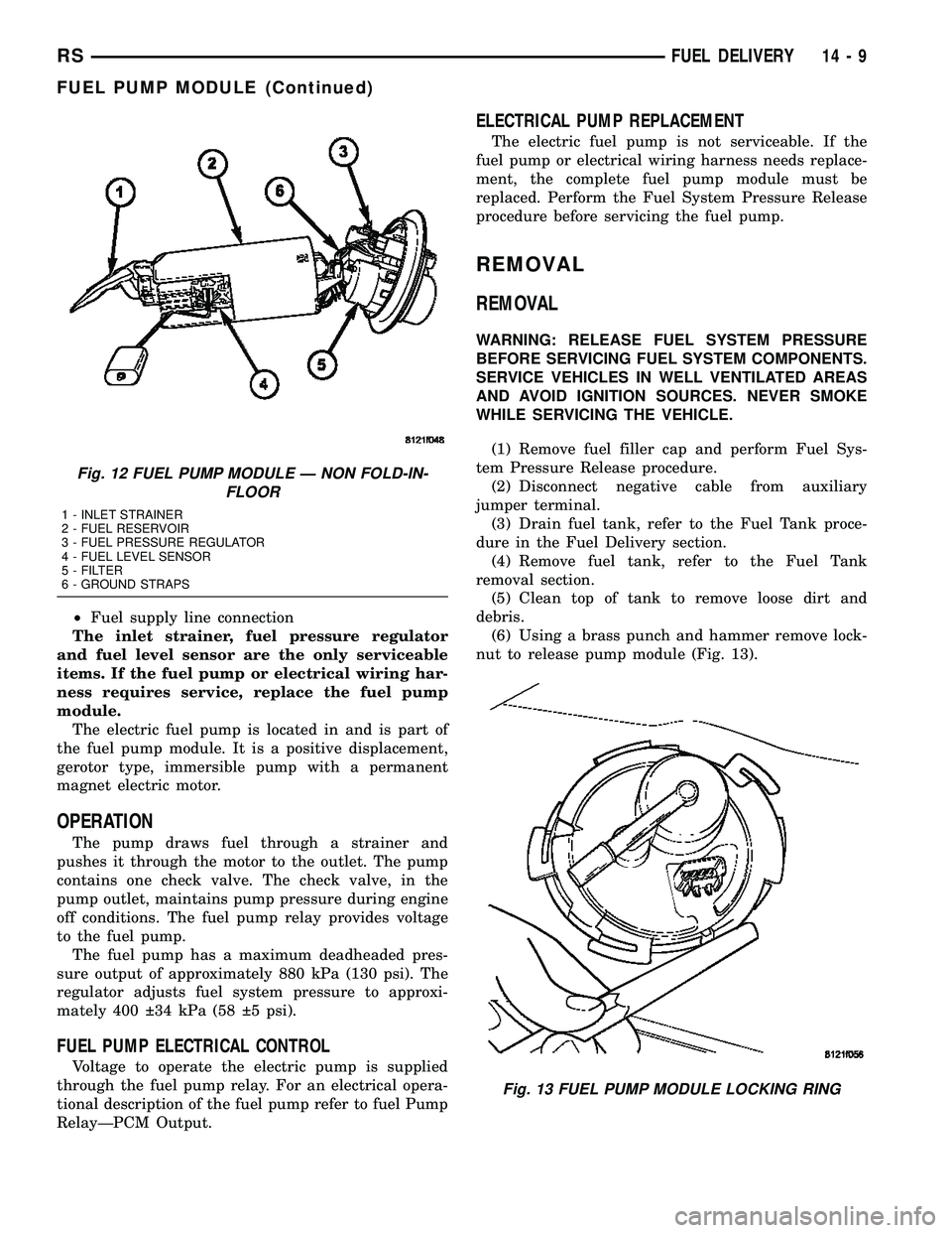
²Fuel supply line connection
The inlet strainer, fuel pressure regulator
and fuel level sensor are the only serviceable
items. If the fuel pump or electrical wiring har-
ness requires service, replace the fuel pump
module.
The electric fuel pump is located in and is part of
the fuel pump module. It is a positive displacement,
gerotor type, immersible pump with a permanent
magnet electric motor.
OPERATION
The pump draws fuel through a strainer and
pushes it through the motor to the outlet. The pump
contains one check valve. The check valve, in the
pump outlet, maintains pump pressure during engine
off conditions. The fuel pump relay provides voltage
to the fuel pump.
The fuel pump has a maximum deadheaded pres-
sure output of approximately 880 kPa (130 psi). The
regulator adjusts fuel system pressure to approxi-
mately 400 34 kPa (58 5 psi).
FUEL PUMP ELECTRICAL CONTROL
Voltage to operate the electric pump is supplied
through the fuel pump relay. For an electrical opera-
tional description of the fuel pump refer to fuel Pump
RelayÐPCM Output.
ELECTRICAL PUMP REPLACEMENT
The electric fuel pump is not serviceable. If the
fuel pump or electrical wiring harness needs replace-
ment, the complete fuel pump module must be
replaced. Perform the Fuel System Pressure Release
procedure before servicing the fuel pump.
REMOVAL
REMOVAL
WARNING: RELEASE FUEL SYSTEM PRESSURE
BEFORE SERVICING FUEL SYSTEM COMPONENTS.
SERVICE VEHICLES IN WELL VENTILATED AREAS
AND AVOID IGNITION SOURCES. NEVER SMOKE
WHILE SERVICING THE VEHICLE.
(1) Remove fuel filler cap and perform Fuel Sys-
tem Pressure Release procedure.
(2) Disconnect negative cable from auxiliary
jumper terminal.
(3) Drain fuel tank, refer to the Fuel Tank proce-
dure in the Fuel Delivery section.
(4) Remove fuel tank, refer to the Fuel Tank
removal section.
(5) Clean top of tank to remove loose dirt and
debris.
(6) Using a brass punch and hammer remove lock-
nut to release pump module (Fig. 13).
Fig. 12 FUEL PUMP MODULE Ð NON FOLD-IN-
FLOOR
1 - INLET STRAINER
2 - FUEL RESERVOIR
3 - FUEL PRESSURE REGULATOR
4 - FUEL LEVEL SENSOR
5 - FILTER
6 - GROUND STRAPS
Fig. 13 FUEL PUMP MODULE LOCKING RING
RSFUEL DELIVERY14-9
FUEL PUMP MODULE (Continued)
Page 1375 of 2339
WARNING: THE FUEL RESERVOIR OF THE FUEL
PUMP MODULE DOES NOT EMPTY OUT WHEN THE
TANK IS DRAINED. THE FUEL IN THE RESERVOIR
MAY SPILL OUT WHEN THE MODULE IS REMOVED.
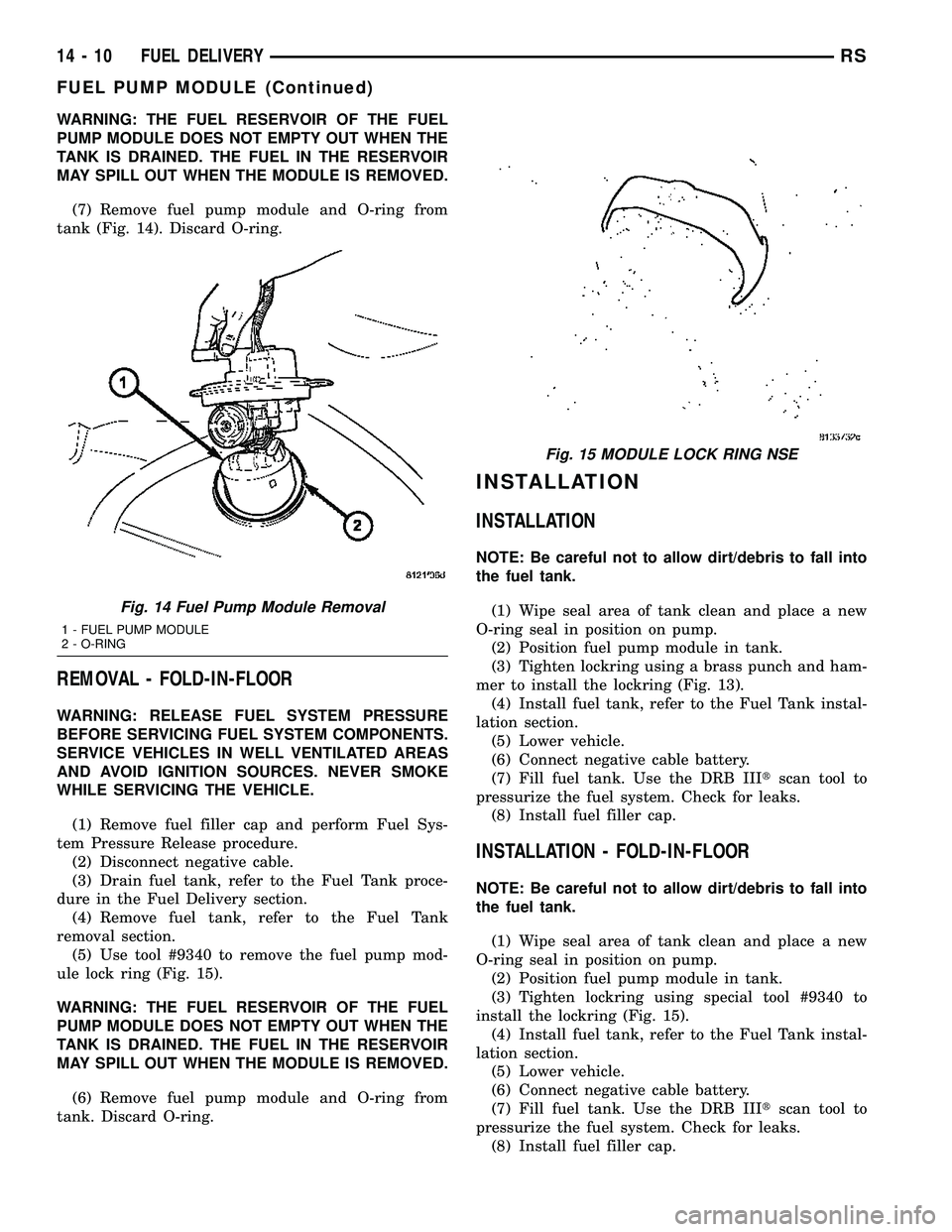
(7) Remove fuel pump module and O-ring from
tank (Fig. 14). Discard O-ring.
REMOVAL - FOLD-IN-FLOOR
WARNING: RELEASE FUEL SYSTEM PRESSURE
BEFORE SERVICING FUEL SYSTEM COMPONENTS.
SERVICE VEHICLES IN WELL VENTILATED AREAS
AND AVOID IGNITION SOURCES. NEVER SMOKE
WHILE SERVICING THE VEHICLE.
(1) Remove fuel filler cap and perform Fuel Sys-
tem Pressure Release procedure.
(2) Disconnect negative cable.
(3) Drain fuel tank, refer to the Fuel Tank proce-
dure in the Fuel Delivery section.
(4) Remove fuel tank, refer to the Fuel Tank
removal section.
(5) Use tool #9340 to remove the fuel pump mod-
ule lock ring (Fig. 15).
WARNING: THE FUEL RESERVOIR OF THE FUEL
PUMP MODULE DOES NOT EMPTY OUT WHEN THE
TANK IS DRAINED. THE FUEL IN THE RESERVOIR
MAY SPILL OUT WHEN THE MODULE IS REMOVED.
(6) Remove fuel pump module and O-ring from
tank. Discard O-ring.
INSTALLATION
INSTALLATION
NOTE: Be careful not to allow dirt/debris to fall into
the fuel tank.
(1) Wipe seal area of tank clean and place a new
O-ring seal in position on pump.
(2) Position fuel pump module in tank.
(3) Tighten lockring using a brass punch and ham-
mer to install the lockring (Fig. 13).
(4) Install fuel tank, refer to the Fuel Tank instal-
lation section.
(5) Lower vehicle.
(6) Connect negative cable battery.
(7) Fill fuel tank. Use the DRB IIItscan tool to
pressurize the fuel system. Check for leaks.
(8) Install fuel filler cap.
INSTALLATION - FOLD-IN-FLOOR
NOTE: Be careful not to allow dirt/debris to fall into
the fuel tank.
(1) Wipe seal area of tank clean and place a new
O-ring seal in position on pump.
(2) Position fuel pump module in tank.
(3) Tighten lockring using special tool #9340 to
install the lockring (Fig. 15).
(4) Install fuel tank, refer to the Fuel Tank instal-
lation section.
(5) Lower vehicle.
(6) Connect negative cable battery.
(7) Fill fuel tank. Use the DRB IIItscan tool to
pressurize the fuel system. Check for leaks.
(8) Install fuel filler cap.
Fig. 14 Fuel Pump Module Removal
1 - FUEL PUMP MODULE
2 - O-RING
Fig. 15 MODULE LOCK RING NSE
14 - 10 FUEL DELIVERYRS
FUEL PUMP MODULE (Continued)
Page 1382 of 2339
(8)For RGDisconnect the vent at the top of the
filler tube.
(9) Remove the ground strap.
(10) Remove filler tube at tank.
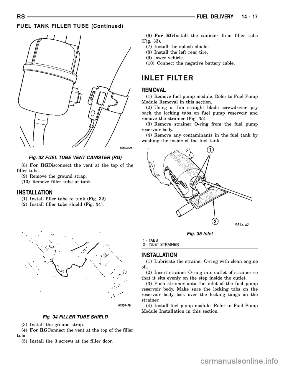
INSTALLATION
(1) Install filler tube to tank (Fig. 32).
(2) Install filler tube shield (Fig. 34).
(3) Install the ground strap.
(4)For RGConnect the vent at the top of the filler
tube.
(5) Install the 3 screws at the filler door.(6)For RGInstall the canister from filler tube
(Fig. 33).
(7) Install the splash shield.
(8) Install the left rear tire.
(9) lower vehicle.
(10) Connect the negative battery cable.
INLET FILTER
REMOVAL
(1) Remove fuel pump module. Refer to Fuel Pump
Module Removal in this section.
(2) Using a thin straight blade screwdriver, pry
back the locking tabs on fuel pump reservoir and
remove the strainer (Fig. 35).
(3) Remove strainer O-ring from the fuel pump
reservoir body.
(4) Remove any contaminants in the fuel tank by
washing the inside of the fuel tank.
INSTALLATION
(1) Lubricate the strainer O-ring with clean engine
oil.
(2) Insert strainer O-ring into outlet of strainer so
that it sits evenly on the step inside the outlet.
(3) Push strainer onto the inlet of the fuel pump
reservoir body. Make sure the locking tabs on the
reservoir body lock over the locking tangs on the
strainer.
(4) Install fuel pump module. Refer to Fuel Pump
Module Installation in this section.
Fig. 33 FUEL TUBE VENT CANISTER (RG)
Fig. 34 FILLER TUBE SHIELD
Fig. 35 Inlet
1 - TABS
2 - INLET STRAINER
RSFUEL DELIVERY14-17
FUEL TANK FILLER TUBE (Continued)
Page 1391 of 2339
The following components access or send informa-
tion on the PCI Bus.
²Instrument Panel
²Body Control Module
²Air Bag System Diagnostic Module
²Full ATC Display Head (if equipped)
²ABS Module
²Transmission Control Module
²Powertrain Control Module
²Travel Module
²SKIMSYSTEM DIAGNOSIS
OPERATION
The PCM can test many of its own input and out-
put circuits. If the PCM senses a fault in a major
system, the PCM stores a Diagnostic Trouble Code
(DTC) in memory.
For DTC information see On-Board Diagnostics
(Refer to 8 - ELECTRICAL/ELECTRONIC CON-
TROL MODULES/POWERTRAIN CONTROL MOD-
ULE - DESCRIPTION) .
SPECIFICATIONS
TORQUE
DESCRIPTION N´m Ft. Lbs. In. Lbs.
MAP SENSOR PLASTIC
MANIFOLD1.7 15
MAP SENSOR
ALUMINUM MANIFOLD3.3 30
POWER STEERING
RESERVOIR PLASTIC
MANIFOLD5.7 50
POWER STEERING
RESERVOIR ALUMINUM
MANIFOLD11.9 105
THROTTLE CABLE
BRACKET PLASTIC
MANIFOLD5.7 50
THROTTLE CABLE
BRACKET ALUMINUM
MANIFOLD11.9 105
EGR TUBE PLASTIC
MANIFOLD5.7 50
EGR TUBE ALUMINUM
MANIFOLD11.9 105
THROTTLE BODY BOLTS
2.4L28 20.65 250 50
THROTTLE BODY BOLTS
3.3/3.8L11.8 8.7 105 20
O2 Sensors 27 20
The composite manifolds uses special Plastic screws. The factory installed Plastic screws can be removed and
installed up to 5 times. Do not exceed the specified torque. These screws must be installed slowly (less than 600
rpms) to avoid melting the parent material. There are service repair screws avialable for repair. They require a
higher torque than the original screws..
14 - 26 FUEL INJECTIONRS
FUEL INJECTION (Continued)
Page 1403 of 2339

REMOVAL - UPSTREAM 1/1 - 3.3/3.8L
(1) Remove battery, refer to the Battery section for
more information.
(2) Remove the battery tray, refer to the Battery
section for more information.
(3) Disconnect the speed control vacuum harness
from servo.
(4) Disconnect the electrical connector from servo.
(5) Remove the speed control servo and bracket
and reposition.
(6) Use a socket such as the Snap-OntYA8875 or
equivalent to remove the sensor (Fig. 25).
(7) When the sensor is removed, the threads must
be cleaned with an 18 mm X 1.5 + 6E tap. If using
the original sensor, coat the threads with Loctite
771±64 anti-seize compound or equivalent.
REMOVAL - DOWNSTREAM 1/2 - 2.4/3.3/3.8L
(1) Disconnect the negative battery cable.
(2) Raise and support the vehicle.
(3) Disconnect the electrical connector (Fig. 26).
(4) Use a socket such as the Snap-OntYA8875 or
equivalent to remove the sensor (Fig. 27).
(5) When the sensor is removed, the threads must
be cleaned with an 18 mm X 1.5 + 6E tap. If using
the original sensor, coat the threads with Loctite
771±64 anti-seize compound or equivalent.
INSTALLATION
INSTALLATION - UPSTREAM 1/1 - 2.4L
The engines uses two heated oxygen sensors.
(1) After removing the sensor, the exhaust mani-
fold threads must be cleaned with an 18 mm X 1.5 +
6E tap. If reusing the original sensor, coat the sensor
threads with an anti-seize compound such as Loctite
771- 64 or equivalent. New sensors have compound
on the threads and do not require an additional coat-
ing.
Fig. 25 O2 SENSOR 1/1
Fig. 26 Downstream Oxygen Sensor (1/2)
1 - OXYGEN SENSOR CONNECTOR
2 - CATALYTIC CONVERTER
3 - DOWNSTREAM OXYGEN SENSOR
4 - ENGINE HARNESS CONNECTOR
Fig. 27 DOWNSTREAM 2/1 O2 SENSOR
14 - 38 FUEL INJECTIONRS
O2 SENSOR (Continued)
Page 1404 of 2339
(2) Install sensor and tighten to 27 N´m (20 ft.
lbs.) (Fig. 23).
(3) Connect the electrical connector for the O2 sen-
sor and install onto bracket.
(4) Lower vehicle.
(5) Connect the negative battery cable.
INSTALLATION - UPSTREAM 1/1 - 3.3/3.8L
The engines uses two heated oxygen sensors.
(1) After removing the sensor, the exhaust mani-
fold threads must be cleaned with an 18 mm X 1.5 +
6E tap. If reusing the original sensor, coat the sensor
threads with an anti-seize compound such as Loctite
771- 64 or equivalent. New sensors have compound
on the threads and do not require an additional coat-
ing.
(2) Install sensor and tighten to 27 N´m (20 ft.
lbs.).
(3) Connect the electrical connector for the O2 sen-
sor and install onto bracket.
(4) Connect the electrical connector for the speed
control servo.
(5) Install the speed control servo and bracket
refer to the Speed Control Servo for more informa-
tion.
(6) Connect the speed control vacuum harness to
servo.
(7) Install the battery tray, refer to the Battery
section for more information.
(8) Install battery, refer to the Battery section for
more information.
INSTALLATION DOWNSTREAM 2/1 -
2.4/3.3/3.8L
The O2S is located on the side of the catalytic con-
verter.
Threads of new oxygen sensors are factory coated
with anti-seize compound to aid in removal.DO
NOT add any additional anti-seize compound to
the threads of a new oxygen sensor.
(1) Install sensor and tighten to 27 N´m (20 ft.
lbs.).
(2) Connect the electrical connector.
(3) Lower vehicle.
(4) Install the negative battery cable.
THROTTLE BODY
DESCRIPTION
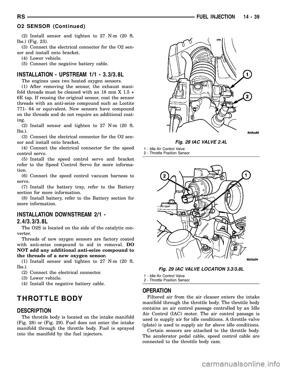
The throttle body is located on the intake manifold
(Fig. 28) or (Fig. 29). Fuel does not enter the intake
manifold through the throttle body. Fuel is sprayed
into the manifold by the fuel injectors.
OPERATION
Filtered air from the air cleaner enters the intake
manifold through the throttle body. The throttle body
contains an air control passage controlled by an Idle
Air Control (IAC) motor. The air control passage is
used to supply air for idle conditions. A throttle valve
(plate) is used to supply air for above idle conditions.
Certain sensors are attached to the throttle body.
The accelerator pedal cable, speed control cable are
connected to the throttle body cam.
Fig. 28 IAC VALVE 2.4L
1 - Idle Air Control Valve
2 - Throttle Position Sensor
Fig. 29 IAC VALVE LOCATION 3.3/3.8L
1 - Idle Air Control Valve
2 - Throttle Position Sensor
RSFUEL INJECTION14-39
O2 SENSOR (Continued)
Page 1408 of 2339
STEERING
TABLE OF CONTENTS
page page
STEERING
DESCRIPTION - POWER STEERING SYSTEM . . 1
OPERATION - POWER STEERING SYSTEM . . . 1
DIAGNOSIS AND TESTING
DIAGNOSIS AND TESTING - POWER
STEERING SYSTEM FLOW AND
PRESSURE TEST......................1
DIAGNOSIS AND TESTING - STEERING
SYSTEM DIAGNOSIS CHARTS............3SPECIFICATIONS
POWER STEERING FASTENER TORQUE . . . 9
SPECIAL TOOLS
POWER STEERING....................9
COLUMN..............................10
GEAR.................................26
PUMP.................................36
STEERING
DESCRIPTION - POWER STEERING SYSTEM
This vehicle comes with power steering as stan-
dard equipment. The power steering system consists
of these major components:
²POWER STEERING PUMP
²POWER STEERING GEAR
²POWER STEERING FLUID
²POWER STEERING FLUID COOLER (If
Equipped)
²POWER STEERING FLUID RESERVOIR
²POWER STEERING FLUID SUPPLY HOSE
²POWER STEERING FLUID PRESSURE HOSE
²POWER STEERING FLUID RETURN HOSE
For information on the first two components, refer
to their respective sections within this service man-
ual group. Information on all other components can
be found in POWER STEERING PUMP.
OPERATION - POWER STEERING SYSTEM
Turning of the steering wheel is converted into lin-
ear (side-to-side) travel through the meshing of the
helical pinion teeth with the rack teeth within the
steering gear. The lateral travel pushes and pulls the
tie rods to change the direction of the vehicle's front
wheels.
Power assist steering is provided by a belt driven
rotary type pump. It directs fluid through power
steering fluid hoses to the power steering gear where
it is used to assist the driver's turning effort.
Manual steering control of the vehicle can be main-
tained if power steering assist is lost. However,
under this condition, steering effort is significantly
increased.
DIAGNOSIS AND TESTING
DIAGNOSIS AND TESTING - POWER STEERING
SYSTEM FLOW AND PRESSURE TEST
ALL ENGINES
The following procedure is to be used to test the
operation of the power steering system on this vehi-
cle. This test will provide the flow rate of the power
steering pump along with the maximum relief pres-
sure. This test is to be performed to determine if the
power steering pump or power steering gear is not
functioning properly. The following flow and pressure
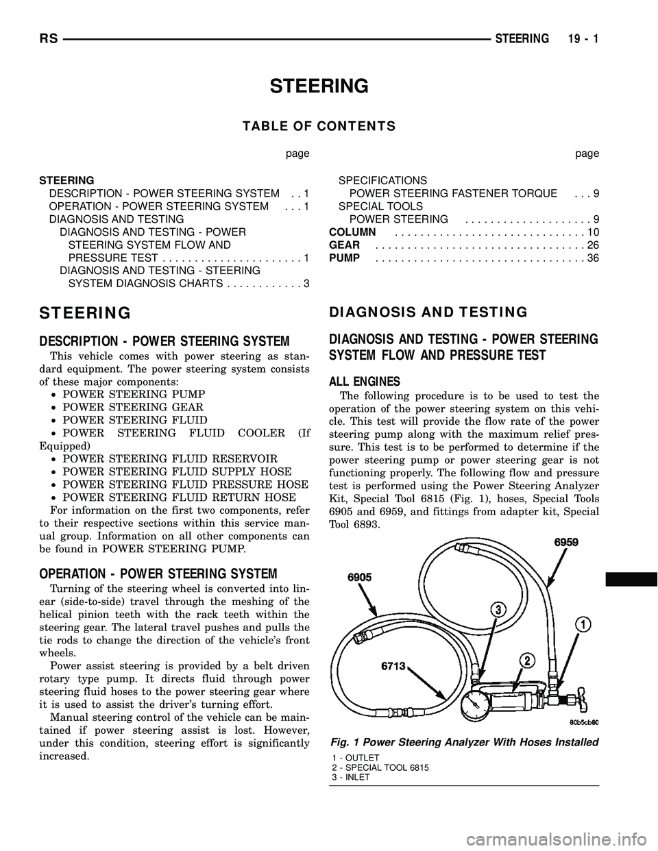
test is performed using the Power Steering Analyzer
Kit, Special Tool 6815 (Fig. 1), hoses, Special Tools
6905 and 6959, and fittings from adapter kit, Special
Tool 6893.
Fig. 1 Power Steering Analyzer With Hoses Installed
1 - OUTLET
2 - SPECIAL TOOL 6815
3 - INLET
RSSTEERING19-1
Page 1411 of 2339
CONDITION POSSIBLE CAUSES CORRECTION
4. Loose lower control arm mounting
bolts at front suspension
crossmember.4. Tighten control arm mounting bolts to
the specified torques.
5. Lower control arm pivot bushing
worn.5. Replace lower control arm pivot
bushing.
6. Loose strut assembly mounting
fasteners at tower or knuckle.6. Tighten strut assembly fasteners to
the specified torque.
7. Power steering fluid hose touching
the body of the vehicle.7. Adjust hose to proper position by
loosening, repositioning, and tightening
attachments to specified torque. Do not
bend tubing.
8. Damaged front suspension
crossmember.8. Replace front suspension
crossmember.
9. Stabilizer bar link ball joints worn. 9. Replace stabilizer bar link.
10. Lug nuts loose. 10. Tighten lug nuts to specifications.
11. Excessive Wheel bearing
free-play.11. Verify correct halfshaft hub nut
torque. Replace hub and bearing if
torque is okay.
12. Internal power steering gear
noise.12. Replace power steering gear.
POPPING NOISE 1. Worn outer tie rod. 1. Check ball joint for free-play;
Replace outer tie rod.
2. Loose inner tie rod. 2. Replace power steering gear.
CHIRP OR SQUEAL
(POWER STEERING
PUMP)1. Loose power steering pump drive
belt.1. Check and adjust power steering
pump drive belt to specifications or
replace automatic tensioner where
applicable. Replace belt if worn or
glazed.
2. Malfuctioning belt auto-tensioner 2. Replace belt auto-tensioner.
WHINE, GROWL, MOAN
OR GROAN (POWER
STEERING PUMP)***1. Low fluid level. 1. Fill power steering fluid reservoir to
proper level and check for leaks (make
sure all air is bled from the system
fluid).
2. Power steering hose touching
vehicle body or frame.2. Adjust hose to proper position by
loosening, repositioning, and tightening
fitting to specified torque. Do not bend
tubing. Replace hose if damaged.
3. Extremely low ambient
temperature.3. Some noise can be expected, but will
go away as vehicle warms. Replace
pump if noise is excessive.
4. Extreme wear of power steering
pump internal components.4. Replace power steering pump and
flush system as necessary.
19 - 4 STEERINGRS
STEERING (Continued)