2005 CHRYSLER CARAVAN body
[x] Cancel search: bodyPage 2238 of 2339
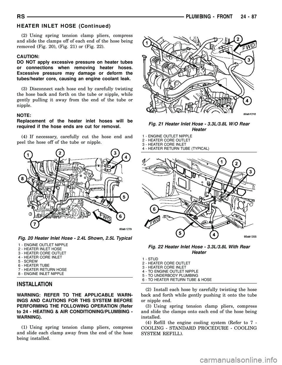
(2) Using spring tension clamp pliers, compress
and slide the clamps off of each end of the hose being
removed (Fig. 20), (Fig. 21) or (Fig. 22).
CAUTION:
DO NOT apply excessive pressure on heater tubes
or connections when removing heater hoses.
Excessive pressure may damage or deform the
tubes/heater core, causing an engine coolant leak.
(3) Disconnect each hose end by carefully twisting
the hose back and forth on the tube or nipple, while
gently pulling it away from the end of the tube or
nipple.
NOTE:
Replacement of the heater inlet hoses will be
required if the hose ends are cut for removal.
(4) If necessary, carefully cut the hose end and
peel the hose off of the tube or nipple.
INSTALLATION
WARNING: REFER TO THE APPLICABLE WARN-
INGS AND CAUTIONS FOR THIS SYSTEM BEFORE
PERFORMING THE FOLLOWING OPERATION (Refer
to 24 - HEATING & AIR CONDITIONING/PLUMBING -
WARNING).
(1) Using spring tension clamp pliers, compress
and slide each clamp away from the end of the hose
being installed.(2) Install each hose by carefully twisting the hose
back and forth while gently pushing it onto the tube
or nipple end.
(3) Using spring tension clamp pliers, compress
and slide the clamps onto each end of the hose being
installed.
(4) Refill the engine cooling system (Refer to 7 -
COOLING - STANDARD PROCEDURE - COOLING
SYSTEM REFILL).
Fig. 20 Heater Inlet Hose - 2.4L Shown, 2.5L Typical
1 - ENGINE OUTLET NIPPLE
2 - HEATER INLET HOSE
3 - HEATER CORE OUTLET
4 - HEATER CORE INLET
5 - SCREW
6 - HEATER TUBE
7 - HEATER RETURN HOSE
8 - ENGINE INLET NIPPLE
Fig. 21 Heater Inlet Hose - 3.3L/3.8L W/O Rear
Heater
1 - ENGINE OUTLET NIPPLE
2 - HEATER CORE OUTLET
3 - HEATER CORE INLET
4 - HEATER RETURN TUBE (TYPICAL)
Fig. 22 Heater Inlet Hose - 3.3L/3.8L With Rear
Heater
1 - STUD
2 - HEATER CORE OUTLET
3 - HEATER CORE INLET
4 - TO ENGINE OUTLET NIPPLE
5 - TO UNDERBODY PLUMBING
6 - TO HEATER RETURN TUBE & HOSE
RSPLUMBING - FRONT24-87
HEATER INLET HOSE (Continued)
Page 2240 of 2339
INSTALLATION
WARNING: REFER TO THE APPLICABLE WARN-
INGS AND CAUTIONS FOR THIS SYSTEM BEFORE
PERFORMING THE FOLLOWING OPERATION (Refer
to 24 - HEATING & AIR CONDITIONING/PLUMBING -
WARNING).
(1) Using spring tension clamp pliers, compress
and slide the clamp away from the end of the heater
return hose.
(2) Install each hose end by carefully twisting the
hose back and forth while gently pushing it onto the
tube.
(3) Using spring tension clamp pliers, compress
and slide the clamps onto each end of the heater
return hose.
(4) Refill the engine cooling system (Refer to 7 -
COOLING - STANDARD PROCEDURE).
LIQUID LINE
REMOVAL
WARNING: REFER TO THE APPLICABLE WARN-
INGS AND CAUTIONS FOR THIS SYSTEM BEFORE
PERFORMING THE FOLLOWING OPERATION (Refer
to 24 - HEATING & AIR CONDITIONING/PLUMBING -
FRONT - WARNING - A/C PLUMBING) and (Refer to
24 - HEATING & AIR CONDITIONING/PLUMBING -
FRONT - CAUTION - A/C PLUMBING).NOTE: The front A/C liquid line is serviced in two
sections. The front section connects between the
A/C condenser and the receiver/drier and includes
the high side service port. The rear section con-
nects between the receiver/drier and the expansion
valve and includes the fitting for the A/C pressure
transducer. On models equipped with the optional
rear heating-A/C system, the rear section of the
front A/C liquid line also includes a hose and tube
extension that connects the front liquid line to the
liquid line for the rear A/C system.
FRONT SECTION
(1) Recover the refrigerant from the refrigerant
system (Refer to 24 - HEATING & AIR CONDITION-
ING/PLUMBING - FRONT/REFRIGERANT - STAN-
DARD PROCEDURE - REFRIGERANT SYSTEM
RECOVERY).
(2) Disconnect and isolate the negative battery
cable.
(3) Remove the air cleaner housing from the right
side of the engine compartment.
(4) Remove the two large screws that secure the
front fascia and the outboard ends of the radiator
sight shield to the radiator closure panel crossmem-
ber (Fig. 26).
(5) Remove the five small screws that secure the
front fascia grille inserts to the radiator sight shield.
(6) Remove the radiator sight shield from the radi-
ator closure panel crossmember.
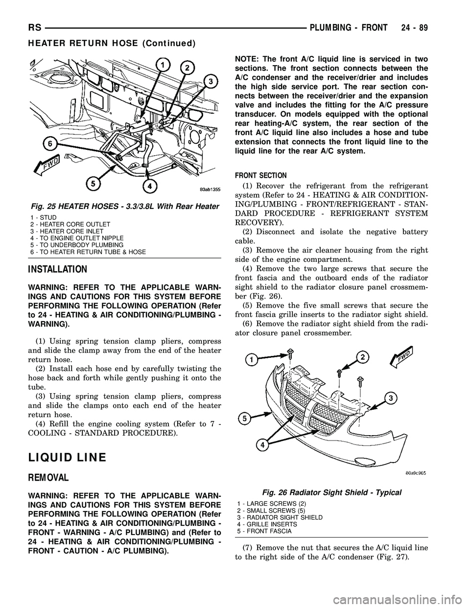
(7) Remove the nut that secures the A/C liquid line
to the right side of the A/C condenser (Fig. 27).
Fig. 25 HEATER HOSES - 3.3/3.8L With Rear Heater
1 - STUD
2 - HEATER CORE OUTLET
3 - HEATER CORE INLET
4 - TO ENGINE OUTLET NIPPLE
5 - TO UNDERBODY PLUMBING
6 - TO HEATER RETURN TUBE & HOSE
Fig. 26 Radiator Sight Shield - Typical
1 - LARGE SCREWS (2)
2 - SMALL SCREWS (5)
3 - RADIATOR SIGHT SHIELD
4 - GRILLE INSERTS
5 - FRONT FASCIA
RSPLUMBING - FRONT24-89
HEATER RETURN HOSE (Continued)
Page 2242 of 2339
(15) If the vehicle is equipped with the optional
rear heating-A/C system, go to Step 16. If the vehicle
is not equipped with the optional rear heating-A/C
system, go to Step 22.
(16) Raise and support the vehicle.
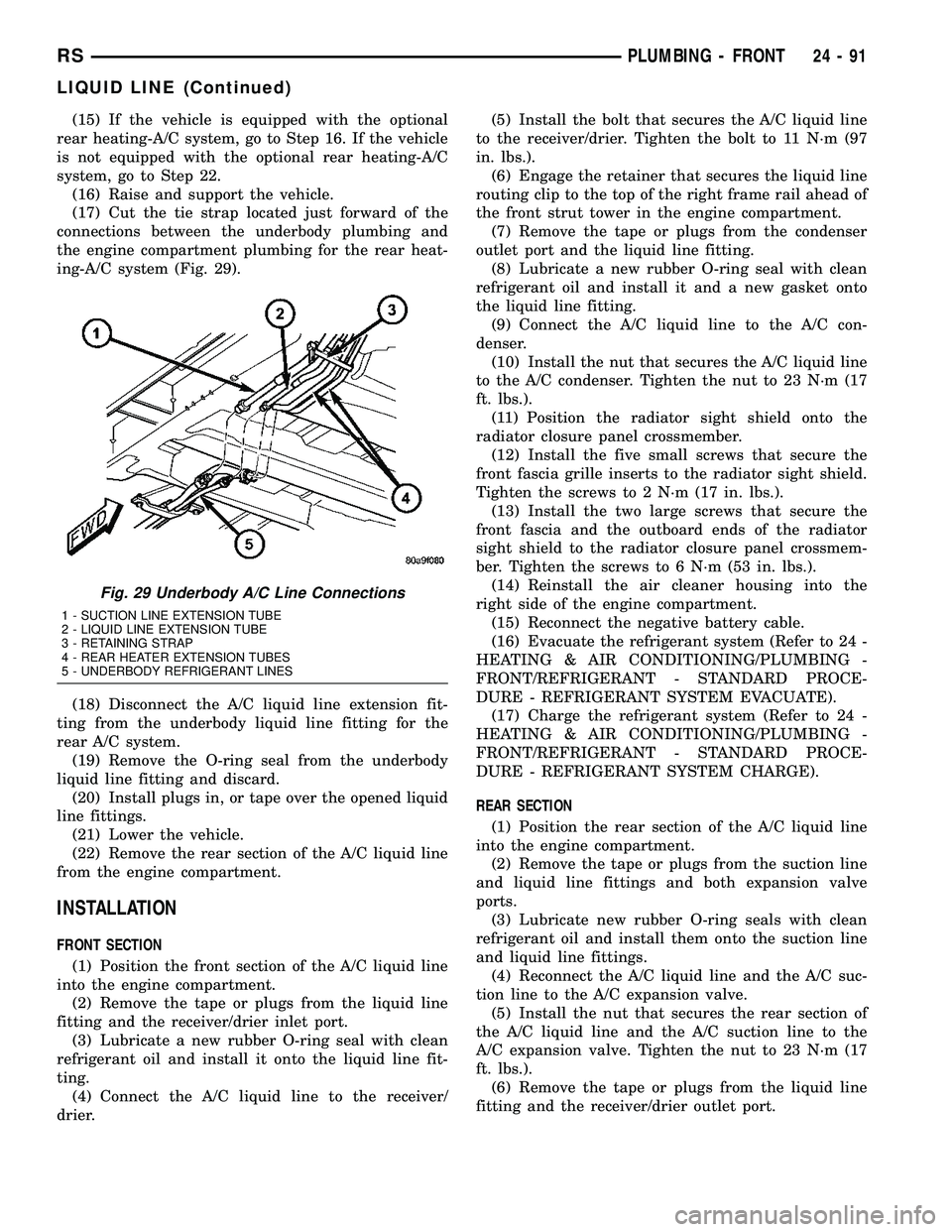
(17) Cut the tie strap located just forward of the
connections between the underbody plumbing and
the engine compartment plumbing for the rear heat-
ing-A/C system (Fig. 29).
(18) Disconnect the A/C liquid line extension fit-
ting from the underbody liquid line fitting for the
rear A/C system.
(19) Remove the O-ring seal from the underbody
liquid line fitting and discard.
(20) Install plugs in, or tape over the opened liquid
line fittings.
(21) Lower the vehicle.
(22) Remove the rear section of the A/C liquid line
from the engine compartment.
INSTALLATION
FRONT SECTION
(1) Position the front section of the A/C liquid line
into the engine compartment.
(2) Remove the tape or plugs from the liquid line
fitting and the receiver/drier inlet port.
(3) Lubricate a new rubber O-ring seal with clean
refrigerant oil and install it onto the liquid line fit-
ting.
(4) Connect the A/C liquid line to the receiver/
drier.(5) Install the bolt that secures the A/C liquid line
to the receiver/drier. Tighten the bolt to 11 N´m (97
in. lbs.).
(6) Engage the retainer that secures the liquid line
routing clip to the top of the right frame rail ahead of
the front strut tower in the engine compartment.
(7) Remove the tape or plugs from the condenser
outlet port and the liquid line fitting.
(8) Lubricate a new rubber O-ring seal with clean
refrigerant oil and install it and a new gasket onto
the liquid line fitting.
(9) Connect the A/C liquid line to the A/C con-
denser.
(10) Install the nut that secures the A/C liquid line
to the A/C condenser. Tighten the nut to 23 N´m (17
ft. lbs.).
(11) Position the radiator sight shield onto the
radiator closure panel crossmember.
(12) Install the five small screws that secure the
front fascia grille inserts to the radiator sight shield.
Tighten the screws to 2 N´m (17 in. lbs.).
(13) Install the two large screws that secure the
front fascia and the outboard ends of the radiator
sight shield to the radiator closure panel crossmem-
ber. Tighten the screws to 6 N´m (53 in. lbs.).
(14) Reinstall the air cleaner housing into the
right side of the engine compartment.
(15) Reconnect the negative battery cable.
(16) Evacuate the refrigerant system (Refer to 24 -
HEATING & AIR CONDITIONING/PLUMBING -
FRONT/REFRIGERANT - STANDARD PROCE-
DURE - REFRIGERANT SYSTEM EVACUATE).
(17) Charge the refrigerant system (Refer to 24 -
HEATING & AIR CONDITIONING/PLUMBING -
FRONT/REFRIGERANT - STANDARD PROCE-
DURE - REFRIGERANT SYSTEM CHARGE).
REAR SECTION
(1) Position the rear section of the A/C liquid line
into the engine compartment.
(2) Remove the tape or plugs from the suction line
and liquid line fittings and both expansion valve
ports.
(3) Lubricate new rubber O-ring seals with clean
refrigerant oil and install them onto the suction line
and liquid line fittings.
(4) Reconnect the A/C liquid line and the A/C suc-
tion line to the A/C expansion valve.
(5) Install the nut that secures the rear section of
the A/C liquid line and the A/C suction line to the
A/C expansion valve. Tighten the nut to 23 N´m (17
ft. lbs.).
(6) Remove the tape or plugs from the liquid line
fitting and the receiver/drier outlet port.
Fig. 29 Underbody A/C Line Connections
1 - SUCTION LINE EXTENSION TUBE
2 - LIQUID LINE EXTENSION TUBE
3 - RETAINING STRAP
4 - REAR HEATER EXTENSION TUBES
5 - UNDERBODY REFRIGERANT LINES
RSPLUMBING - FRONT24-91
LIQUID LINE (Continued)
Page 2243 of 2339
(7) Lubricate a new rubber O-ring seal with clean
refrigerant oil and install it on the liquid line fitting.
(8) Reconnect the A/C liquid line to the receiver/
drier.
(9) Install the bolt that secures the A/C liquid line
to the receiver/drier. Tighten the bolt to 11 N´m (97
in. lbs.).
(10) If equipped, reinstall the A/C ground strap
eyelet terminal connector onto the weld stud on the
top of the right front strut tower (if equipped).
(11) If equipped, install the nut that secures the
A/C ground strap to the weld stud. Tighten the nut
to 12 N´m (106 in. lbs.)
(12) Install the A/C pressure transducer (Refer to
24 - HEATING & AIR CONDITIONING/CONTROLS
- FRONT/A/C PRESSURE TRANSDUCER - INSTAL-
LATION).
(13) Connect the drain tube to the wiper module
drain on the right side of the engine compartment.
(14) Install the air cleaner housing into the right
side of the engine compartment.
(15) On RHD models, install the liquid line into
the retaining bracket located at the top of the dash
panel.
(16) If the vehicle is equipped with the optional
rear heating-A/C system, go to Step 17. If the vehicle
does not have the optional rear heating-A/C system,
go to Step 23.
(17) Raise and support the vehicle.
(18) Remove the tape or plugs from the A/C liquid
line extension fitting and the underbody liquid line
fitting.
(19) Lubricate a new rubber O-ring seal with clean
refrigerant oil and install it on the underbody liquid
line fitting.
(20) Connect the A/C liquid line extension fitting
to the underbody liquid line fitting. Tighten the fit-
tings to 23 N´m (17 ft. lbs.).
(21) Install a new tie strap just forward of the con-
nections between the underbody plumbing and the
engine compartment plumbing for the rear heating-
A/C system.
(22) Lower the vehicle.
(23) Reconnect the negative battery cable.
(24) Evacuate the refrigerant system (Refer to 24 -
HEATING & AIR CONDITIONING/PLUMBING -
FRONT/REFRIGERANT - STANDARD PROCE-
DURE - REFRIGERANT SYSTEM EVACUATE).
(25) Charge the refrigerant system (Refer to 24 -
HEATING & AIR CONDITIONING/PLUMBING -
FRONT/REFRIGERANT - STANDARD PROCE-
DURE - REFRIGERANT SYSTEM CHARGE).RECEIVER / DRIER
DESCRIPTION
The receiver/drier is mounted in a bracket secured
to the right front strut tower in the engine compart-
ment. The receiver/drier is connected between the
front and rear sections of the liquid line between the
condenser outlet and the evaporator inlet. The receiv-
er/drier cannot be repaired. If the receiver/drier is
faulty or damaged, or if the refrigerant system has
been contaminated or left open to the atmosphere for
an indeterminable period or if the A/C compressor
has failed, it must be replaced.
OPERATION
The receiver/drier performs a filtering action to
prevent foreign material in the refrigerant from con-
taminating the expansion valve. Desiccant inside the
receiver/drier canister absorbs any moisture which
may have entered and become trapped within the
refrigerant system. In addition, during periods of
high demand air conditioner operation, the receiver/
drier acts as a reservoir to store surplus refrigerant.
Refrigerant enters the receiver/drier as a high-pres-
sure, low temperature liquid.
REMOVAL
WARNING: REFER TO THE APPLICABLE WARN-
INGS AND CAUTIONS FOR THIS SYSTEM BEFORE
PERFORMING THE FOLLOWING OPERATION (Refer
to 24 - HEATING & AIR CONDITIONING/PLUMBING -
FRONT - WARNING - A/C PLUMBING) and (Refer to
24 - HEATING & AIR CONDITIONING/PLUMBING -
FRONT - CAUTION - A/C PLUMBING).
(1) Recover the refrigerant from the refrigerant
system (Refer to 24 - HEATING & AIR CONDITION-
ING/PLUMBING - FRONT/REFRIGERANT - STAN-
DARD PROCEDURE - REFRIGERANT
RECOVERY).
(2) Remove the air cleaner housing from the right
side of the engine compartment.
(3) Remove the bolt that secures the liquid line
front section fitting to the top of the receiver/drier
(Fig. 30).
(4) Disconnect the liquid line fitting from the
receiver/drier inlet port.
(5) Remove the O-ring seal from the liquid line fit-
ting and discard.
(6) Install plugs in, or tape over the opened liquid
line fitting and the receiver/drier inlet port.
24 - 92 PLUMBING - FRONTRS
LIQUID LINE (Continued)
Page 2246 of 2339
rest of the system must be drained from the replace-
ment A/C compressor. The oil capacity of the system,
minus the amount of oil still in the remaining com-
ponents (refer to the oil capacity chart below) can be
measured and poured into the suction port of the A/C
compressor. When a line or component has ruptured
and oil has escaped, the receiver/drier must be
replaced along with the ruptured component.
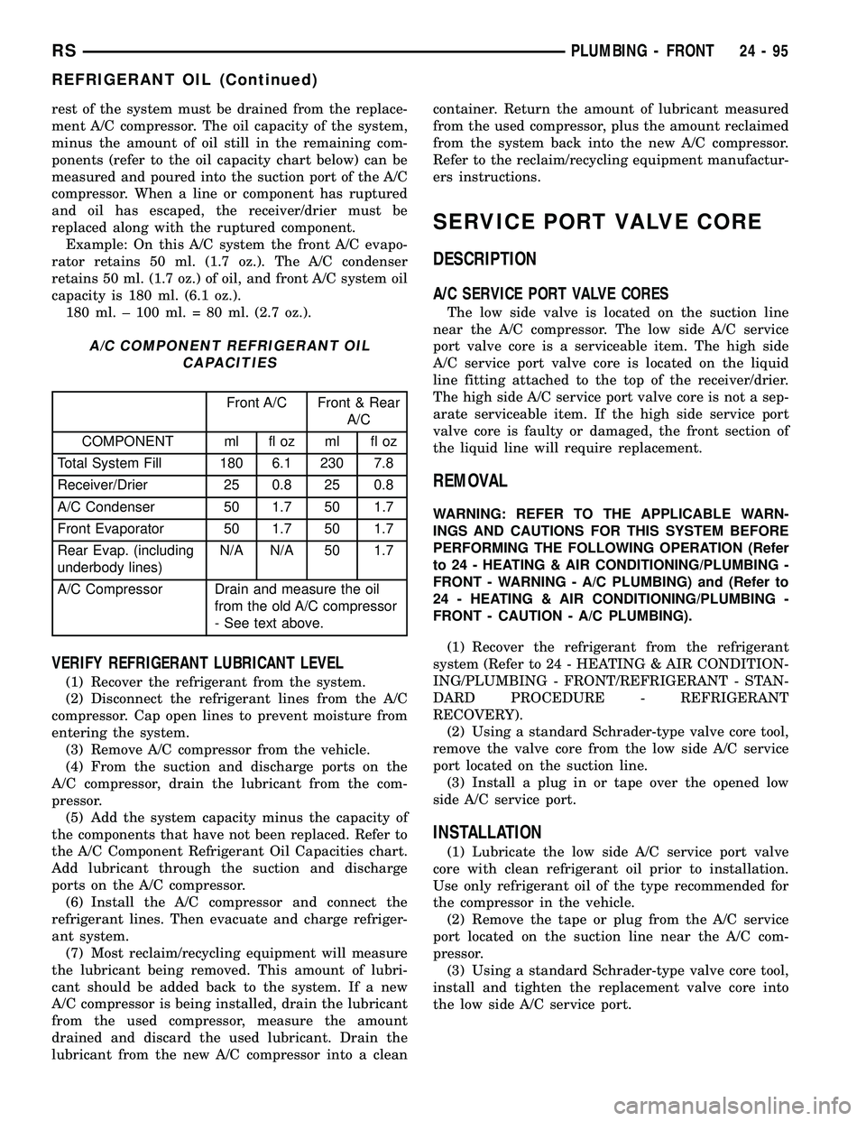
Example: On this A/C system the front A/C evapo-
rator retains 50 ml. (1.7 oz.). The A/C condenser
retains 50 ml. (1.7 oz.) of oil, and front A/C system oil
capacity is 180 ml. (6.1 oz.).
180 ml. ± 100 ml. = 80 ml. (2.7 oz.).
A/C COMPONENT REFRIGERANT OIL
CAPACITIES
Front A/C Front & Rear
A/C
COMPONENT ml fl oz ml fl oz
Total System Fill 180 6.1 230 7.8
Receiver/Drier 25 0.8 25 0.8
A/C Condenser 50 1.7 50 1.7
Front Evaporator 50 1.7 50 1.7
Rear Evap. (including
underbody lines)N/A N/A 50 1.7
A/C Compressor Drain and measure the oil
from the old A/C compressor
- See text above.
VERIFY REFRIGERANT LUBRICANT LEVEL
(1) Recover the refrigerant from the system.
(2) Disconnect the refrigerant lines from the A/C
compressor. Cap open lines to prevent moisture from
entering the system.
(3) Remove A/C compressor from the vehicle.
(4) From the suction and discharge ports on the
A/C compressor, drain the lubricant from the com-
pressor.
(5) Add the system capacity minus the capacity of
the components that have not been replaced. Refer to
the A/C Component Refrigerant Oil Capacities chart.
Add lubricant through the suction and discharge
ports on the A/C compressor.
(6) Install the A/C compressor and connect the
refrigerant lines. Then evacuate and charge refriger-
ant system.
(7) Most reclaim/recycling equipment will measure
the lubricant being removed. This amount of lubri-
cant should be added back to the system. If a new
A/C compressor is being installed, drain the lubricant
from the used compressor, measure the amount
drained and discard the used lubricant. Drain the
lubricant from the new A/C compressor into a cleancontainer. Return the amount of lubricant measured
from the used compressor, plus the amount reclaimed
from the system back into the new A/C compressor.
Refer to the reclaim/recycling equipment manufactur-
ers instructions.
SERVICE PORT VALVE CORE
DESCRIPTION
A/C SERVICE PORT VALVE CORES
The low side valve is located on the suction line
near the A/C compressor. The low side A/C service
port valve core is a serviceable item. The high side
A/C service port valve core is located on the liquid
line fitting attached to the top of the receiver/drier.
The high side A/C service port valve core is not a sep-
arate serviceable item. If the high side service port
valve core is faulty or damaged, the front section of
the liquid line will require replacement.
REMOVAL
WARNING: REFER TO THE APPLICABLE WARN-
INGS AND CAUTIONS FOR THIS SYSTEM BEFORE
PERFORMING THE FOLLOWING OPERATION (Refer
to 24 - HEATING & AIR CONDITIONING/PLUMBING -
FRONT - WARNING - A/C PLUMBING) and (Refer to
24 - HEATING & AIR CONDITIONING/PLUMBING -
FRONT - CAUTION - A/C PLUMBING).
(1) Recover the refrigerant from the refrigerant
system (Refer to 24 - HEATING & AIR CONDITION-
ING/PLUMBING - FRONT/REFRIGERANT - STAN-
DARD PROCEDURE - REFRIGERANT
RECOVERY).
(2) Using a standard Schrader-type valve core tool,
remove the valve core from the low side A/C service
port located on the suction line.
(3) Install a plug in or tape over the opened low
side A/C service port.
INSTALLATION
(1) Lubricate the low side A/C service port valve
core with clean refrigerant oil prior to installation.
Use only refrigerant oil of the type recommended for
the compressor in the vehicle.
(2) Remove the tape or plug from the A/C service
port located on the suction line near the A/C com-
pressor.
(3) Using a standard Schrader-type valve core tool,
install and tighten the replacement valve core into
the low side A/C service port.
RSPLUMBING - FRONT24-95
REFRIGERANT OIL (Continued)
Page 2247 of 2339
CAUTION: A valve core that is not fully seated in
the A/C service port can result in damage to the
valve during refrigerant system evacuation and
charge. Such damage may result in a loss of sys-
tem refrigerant while uncoupling the charge adapt-
ers.
(4) Evacuate the refrigerant system (Refer to 24 -
HEATING & AIR CONDITIONING/PLUMBING -
FRONT/REFRIGERANT - STANDARD PROCE-
DURE - REFRIGERANT SYSTEM EVACUATE).
(5) Charge the refrigerant system (Refer to 24 -
HEATING & AIR CONDITIONING/PLUMBING -
FRONT/REFRIGERANT - STANDARD PROCE-
DURE - REFRIGERANT SYSTEM CHARGE).
(6) Reinstall the protective cap onto the A/C ser-
vice port.
SUCTION LINE
REMOVAL
WARNING: REFER TO THE APPLICABLE WARN-
INGS AND CAUTIONS FOR THIS SYSTEM BEFORE
PERFORMING THE FOLLOWING OPERATION (Refer
to 24 - HEATING & AIR CONDITIONING/PLUMBING -
FRONT - WARNING - A/C PLUMBING) and (Refer to
24 - HEATING & AIR CONDITIONING/PLUMBING -
FRONT - CAUTION - A/C PLUMBING).
NOTE: The front suction line includes the low side
service port on a section of tubing located near the
A/C compressor. On models equipped with the
optional rear A/C system, the front suction line also
includes a suction line hose and tube extension
that connects the front suction line to the suction
line for the rear A/C system.
(1) Recover the refrigerant from the refrigerant
system (Refer to 24 - HEATING & AIR CONDITION-
ING/PLUMBING - FRONT/REFRIGERANT - STAN-
DARD PROCEDURE - REFRIGERANT
RECOVERY).
(2) Disconnect and isolate the battery negative
cable.
(3) Remove the air cleaner top cover and snorkel
from the air cleaner housing located on the right side
of the engine compartment.
(4) Disconnect the drain tube from the wiper mod-
ule drain on the right side of the engine compart-
ment.
(5) Remove the nut that secures the suction line
fitting to the top of the A/C compressor.
(6) Disconnect the suction line fitting from the
compressor suction port.(7) Remove the O-ring seal from the suction line
fitting and discard.
(8) Install plugs in, or tape over the opened suc-
tion line fitting and the compressor suction port.
(9) Remove the retainer that secures the suction
line routing clip to the receiver/drier mounting
bracket on the side of the right front strut tower in
the engine compartment (Fig. 31).
(10) Remove the nut that secures the suction line
and liquid line fittings to the expansion valve.
(11) Disconnect the suction line and liquid line fit-
tings from the expansion valve.
(12) Remove the seals from the suction line and
liquid line fittings and discard.
(13) Install plugs in, or tape over the opened suc-
tion line and liquid line fittings and both expansion
valve ports.
(14) Remove the suction line from the retaining
bracket located at the top of the dash panel.
(15) If the vehicle is equipped with the optional
rear air conditioner, go to Step 16. If the vehicle does
not have the optional rear air conditioner, go to Step
22.
(16) Raise and support the vehicle.
(17) Cut the tie strap located just forward of the
connections between the underbody plumbing and
the engine compartment plumbing for the rear
heater and air conditioner (Fig. 32).
Fig. 31 Suction Line - LHD Shown, RHD Typical
1 - A/C EXPANSION VALVE
2 - SUCTION LINE EXTENSION (REAR A/C ONLY)
3 - NUT
4 - RETAINING CLIP
5 - SUCTION LINE
24 - 96 PLUMBING - FRONTRS
SERVICE PORT VALVE CORE (Continued)
Page 2248 of 2339
(18) Disconnect the suction line extension fitting
from the underbody suction line fitting for the rear
air conditioner.
(19) Remove the O-ring seal from the underbody
suction line fitting and discard.
(20) Install plugs in, or tape over the opened suc-
tion line fittings.
(21) Lower the vehicle.
(22) Remove the suction line from the engine com-
partment.
INSTALLATION
(1) Position the suction line into the engine com-
partment.
(2) Remove the tape or plugs from the suction line
and liquid line fittings and both expansion valve
ports.
(3) Lubricate new rubber O-ring seals with clean
refrigerant oil and install them on the suction line
and liquid line fittings.
(4) Reconnect the liquid line and suction line fit-
tings to the expansion valve.
(5) Install the nut that secures the suction line
and liquid line fittings to the expansion valve.
Tighten the nut to 23 N´m (17 ft. lbs.).
(6) Install the retainer that secures the suction
line routing clip to the receiver/drier mounting
bracket on the side of the right front strut tower in
the engine compartment.(7) Remove the tape or plugs from the compressor
suction port and the suction line fitting.
(8) Lubricate a new rubber O-ring seal with clean
refrigerant oil and install it on the suction line fit-
ting.
(9) Install a new dual plan seal and reconnect the
suction line fitting to the compressor suction port.
(10) Install the nut that secures the suction line
fitting to the A/C compressor. Tighten the nut to 23
N´m (17 ft. lbs.).
(11) Reconnect the drain tube to the wiper module
drain on the right side of the engine compartment.
(12) Install the air cleaner top cover and snorkel
onto the air cleaner housing located on the right side
of the engine compartment.
(13) On RHD models, install the suction line into
the retaining bracket located at the top of the dash
panel.
(14) If the vehicle is equipped with the optional
rear air conditioner, go to Step 15. If the vehicle does
not have the optional rear air conditioner, go to Step
21.
(15) Raise and support the vehicle.
(16) Remove the tape or plugs from the suction
line extension fitting and the underbody suction line
fitting.
(17) Lubricate a new rubber O-ring seal with clean
refrigerant oil and install it on the underbody suction
line fitting.
(18) Reconnect the suction line extension fitting to
the underbody suction line fitting. Tighten the fit-
tings to 23 N´m (17 ft. lbs.).
(19) Install a new tie strap just forward of the con-
nections between the underbody plumbing and the
engine compartment plumbing for the rear heater
and air conditioner.
(20) Lower the vehicle.
(21) Reconnect the battery negative cable.
(22) Evacuate the refrigerant system (Refer to 24 -
HEATING & AIR CONDITIONING/PLUMBING -
FRONT/REFRIGERANT - STANDARD PROCE-
DURE - REFRIGERANT SYSTEM EVACUATE).
(23) Charge the refrigerant system (Refer to 24 -
HEATING & AIR CONDITIONING/PLUMBING -
FRONT/REFRIGERANT - STANDARD PROCE-
DURE - REFRIGERANT SYSTEM CHARGE).
Fig. 32 Underbody A/C Line Connections
1 - SUCTION LINE EXTENSION TUBE
2 - LIQUID LINE EXTENSION TUBE
3 - RETAINING STRAP
4 - REAR HEATER EXTENSION TUBES
5 - UNDERBODY REFRIGERANT LINES
RSPLUMBING - FRONT24-97
SUCTION LINE (Continued)
Page 2249 of 2339
PLUMBING - REAR
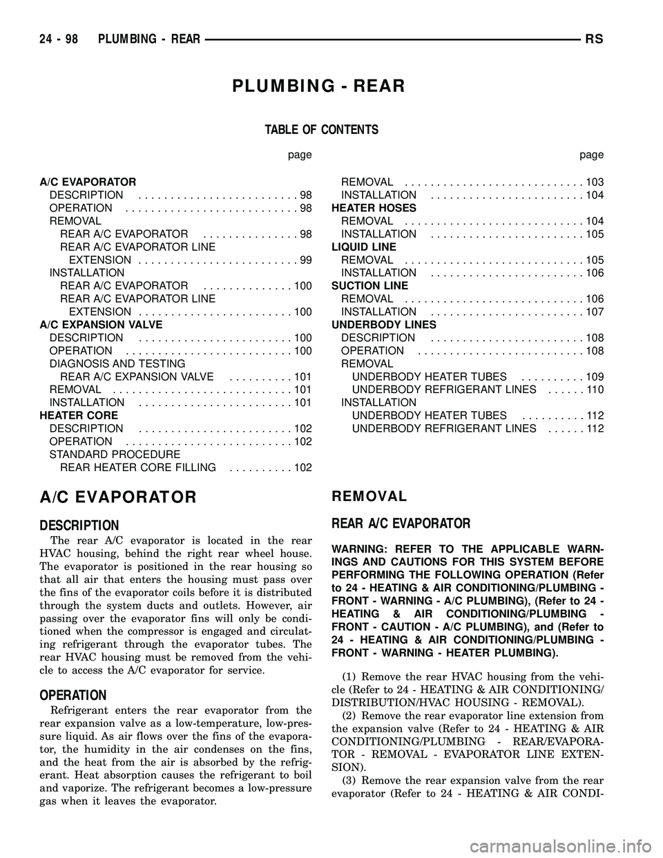
TABLE OF CONTENTS
page page
A/C EVAPORATOR
DESCRIPTION.........................98
OPERATION...........................98
REMOVAL
REAR A/C EVAPORATOR...............98
REAR A/C EVAPORATOR LINE
EXTENSION.........................99
INSTALLATION
REAR A/C EVAPORATOR..............100
REAR A/C EVAPORATOR LINE
EXTENSION........................100
A/C EXPANSION VALVE
DESCRIPTION........................100
OPERATION..........................100
DIAGNOSIS AND TESTING
REAR A/C EXPANSION VALVE..........101
REMOVAL............................101
INSTALLATION........................101
HEATER CORE
DESCRIPTION........................102
OPERATION..........................102
STANDARD PROCEDURE
REAR HEATER CORE FILLING..........102REMOVAL............................103
INSTALLATION........................104
HEATER HOSES
REMOVAL............................104
INSTALLATION........................105
LIQUID LINE
REMOVAL............................105
INSTALLATION........................106
SUCTION LINE
REMOVAL............................106
INSTALLATION........................107
UNDERBODY LINES
DESCRIPTION........................108
OPERATION..........................108
REMOVAL
UNDERBODY HEATER TUBES..........109
UNDERBODY REFRIGERANT LINES......110
INSTALLATION
UNDERBODY HEATER TUBES..........112
UNDERBODY REFRIGERANT LINES......112
A/C EVAPORATOR
DESCRIPTION
The rear A/C evaporator is located in the rear
HVAC housing, behind the right rear wheel house.
The evaporator is positioned in the rear housing so
that all air that enters the housing must pass over
the fins of the evaporator coils before it is distributed
through the system ducts and outlets. However, air
passing over the evaporator fins will only be condi-
tioned when the compressor is engaged and circulat-
ing refrigerant through the evaporator tubes. The
rear HVAC housing must be removed from the vehi-
cle to access the A/C evaporator for service.
OPERATION
Refrigerant enters the rear evaporator from the
rear expansion valve as a low-temperature, low-pres-
sure liquid. As air flows over the fins of the evapora-
tor, the humidity in the air condenses on the fins,
and the heat from the air is absorbed by the refrig-
erant. Heat absorption causes the refrigerant to boil
and vaporize. The refrigerant becomes a low-pressure
gas when it leaves the evaporator.
REMOVAL
REAR A/C EVAPORATOR
WARNING: REFER TO THE APPLICABLE WARN-
INGS AND CAUTIONS FOR THIS SYSTEM BEFORE
PERFORMING THE FOLLOWING OPERATION (Refer
to 24 - HEATING & AIR CONDITIONING/PLUMBING -
FRONT - WARNING - A/C PLUMBING), (Refer to 24 -
HEATING & AIR CONDITIONING/PLUMBING -
FRONT - CAUTION - A/C PLUMBING), and (Refer to
24 - HEATING & AIR CONDITIONING/PLUMBING -
FRONT - WARNING - HEATER PLUMBING).
(1) Remove the rear HVAC housing from the vehi-
cle (Refer to 24 - HEATING & AIR CONDITIONING/
DISTRIBUTION/HVAC HOUSING - REMOVAL).
(2) Remove the rear evaporator line extension from
the expansion valve (Refer to 24 - HEATING & AIR
CONDITIONING/PLUMBING - REAR/EVAPORA-
TOR - REMOVAL - EVAPORATOR LINE EXTEN-
SION).
(3) Remove the rear expansion valve from the rear
evaporator (Refer to 24 - HEATING & AIR CONDI-
24 - 98 PLUMBING - REARRS