2005 CHRYSLER CARAVAN lock
[x] Cancel search: lockPage 1837 of 2339
INSTALLATION
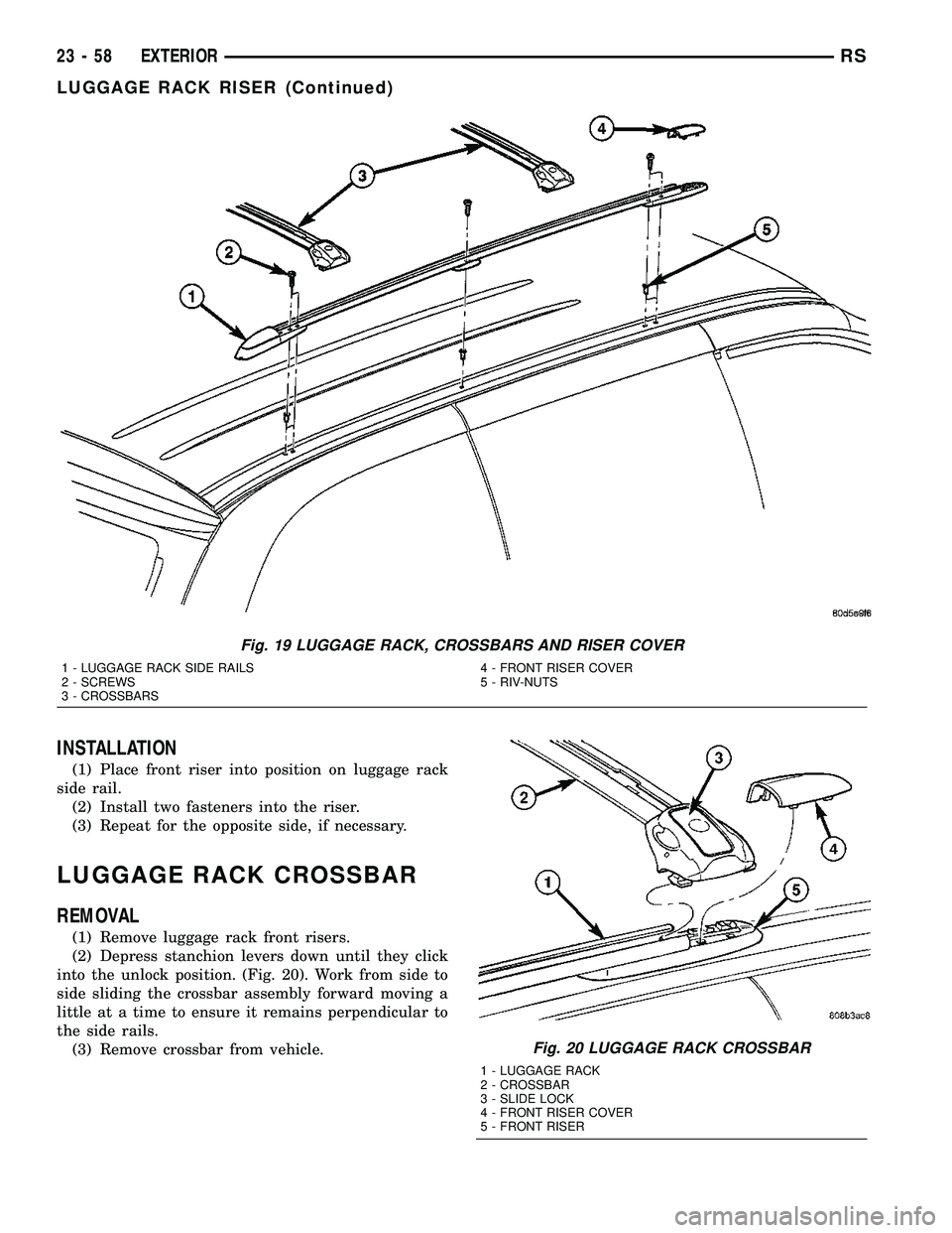
(1) Place front riser into position on luggage rack
side rail.
(2) Install two fasteners into the riser.
(3) Repeat for the opposite side, if necessary.
LUGGAGE RACK CROSSBAR
REMOVAL
(1) Remove luggage rack front risers.
(2) Depress stanchion levers down until they click
into the unlock position. (Fig. 20). Work from side to
side sliding the crossbar assembly forward moving a
little at a time to ensure it remains perpendicular to
the side rails.
(3) Remove crossbar from vehicle.
Fig. 19 LUGGAGE RACK, CROSSBARS AND RISER COVER
1 - LUGGAGE RACK SIDE RAILS
2 - SCREWS
3 - CROSSBARS4 - FRONT RISER COVER
5 - RIV-NUTS
Fig. 20 LUGGAGE RACK CROSSBAR
1 - LUGGAGE RACK
2 - CROSSBAR
3 - SLIDE LOCK
4 - FRONT RISER COVER
5 - FRONT RISER
23 - 58 EXTERIORRS
LUGGAGE RACK RISER (Continued)
Page 1838 of 2339
INSTALLATION
NOTE: The crossbar assemblies are designed to be
installed in only one way. Check top and bottom
surfaces of the crossbar for the word FRONT and
directional arrows. The directional arrows must
point toward the front of the vehicle.
(1) Place crossbar in position on vehicle.
(2) Work from side to side sliding the crossbar
assembly back a little at a time to ensure it remains
perpendicular to the side rails.
(3) Position first crossbar assembly crossbar at the
second most rearward locator holes. Press the top of
the stanchion lever to lock it into position.
(4) Position the second crossbar assembly in the
second hole from the front. Lock into place.
(5) Place luggage rack riser into position.
(6) Install two fasteners into riser. Tighten fasten-
ers to 4 mm (35 in. lbs.) torque.
REAR QUARTER PANEL/
FENDER AIR EXHAUSTER
DESCRIPTION
Air exhausters, designed to conform to the body
structure, allow air entering at the front of the vehi-
cle to flow out the back. By reducing air pressure
within the vehicle, the exhausters also reduce blower
noise at any given air flow level compared to operat-
ing without them and help reduce door closing effort.
They are located in the lower rear comers of the
body.
REMOVAL
SHORT WHEELBASE
(1) Remove the rear fascia from the body. (Refer to
13 - FRAMES & BUMPERS/BUMPERS/REAR FAS-
CIA - REMOVAL).
(2) Using a trim stick or another suitable wide flat
bladed tool, carefully pry the air exhauster away
from the opening in the lower aperture panel until
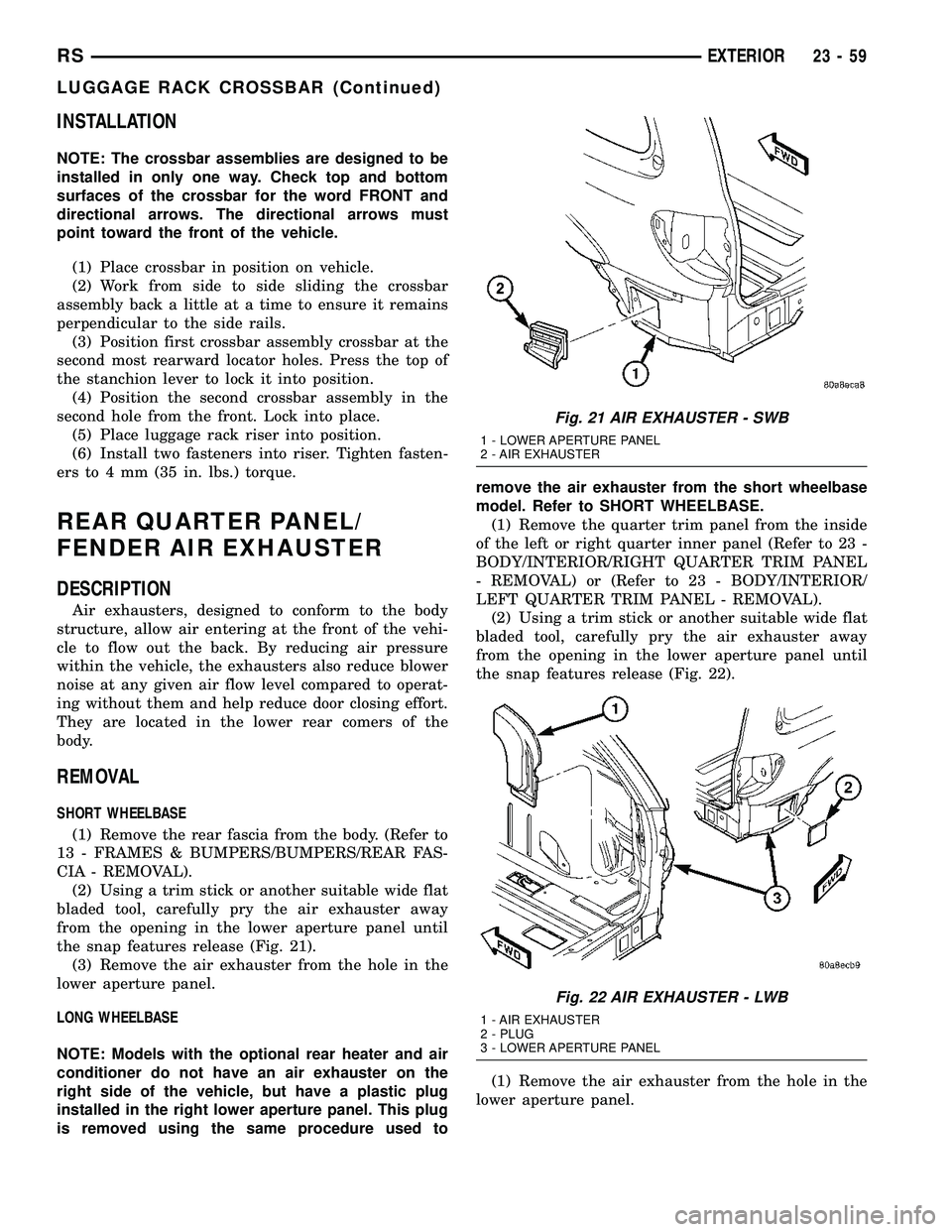
the snap features release (Fig. 21).
(3) Remove the air exhauster from the hole in the
lower aperture panel.
LONG WHEELBASE
NOTE: Models with the optional rear heater and air
conditioner do not have an air exhauster on the
right side of the vehicle, but have a plastic plug
installed in the right lower aperture panel. This plug
is removed using the same procedure used toremove the air exhauster from the short wheelbase
model. Refer to SHORT WHEELBASE.
(1) Remove the quarter trim panel from the inside
of the left or right quarter inner panel (Refer to 23 -
BODY/INTERIOR/RIGHT QUARTER TRIM PANEL
- REMOVAL) or (Refer to 23 - BODY/INTERIOR/
LEFT QUARTER TRIM PANEL - REMOVAL).
(2) Using a trim stick or another suitable wide flat
bladed tool, carefully pry the air exhauster away
from the opening in the lower aperture panel until
the snap features release (Fig. 22).
(1) Remove the air exhauster from the hole in the
lower aperture panel.
Fig. 21 AIR EXHAUSTER - SWB
1 - LOWER APERTURE PANEL
2 - AIR EXHAUSTER
Fig. 22 AIR EXHAUSTER - LWB
1 - AIR EXHAUSTER
2 - PLUG
3 - LOWER APERTURE PANEL
RSEXTERIOR23-59
LUGGAGE RACK CROSSBAR (Continued)
Page 1842 of 2339
INSTALLATION
(1) Place hood in position on vehicle. With assis-
tance from a helper at the opposite side of the vehicle
to support the hood, install bottom bolts attaching
hood to hinge finger tight.
(2) Install top bolts attaching hood to hinge finger
tight.
(3) Position bolts at marks and tighten. Tighten
bolts to 13.5 N´m (120 in. lbs.) torque. The hood
should be aligned to 4 mm (0.160 in.) gap to the front
fenders and flush across the top surfaces along fend-
ers.
(4) Verify hood operation and alignment.
LATCH
REMOVAL
(1) Release hood latch and open hood.
(2) Remove bolts attaching hood latch to radiator
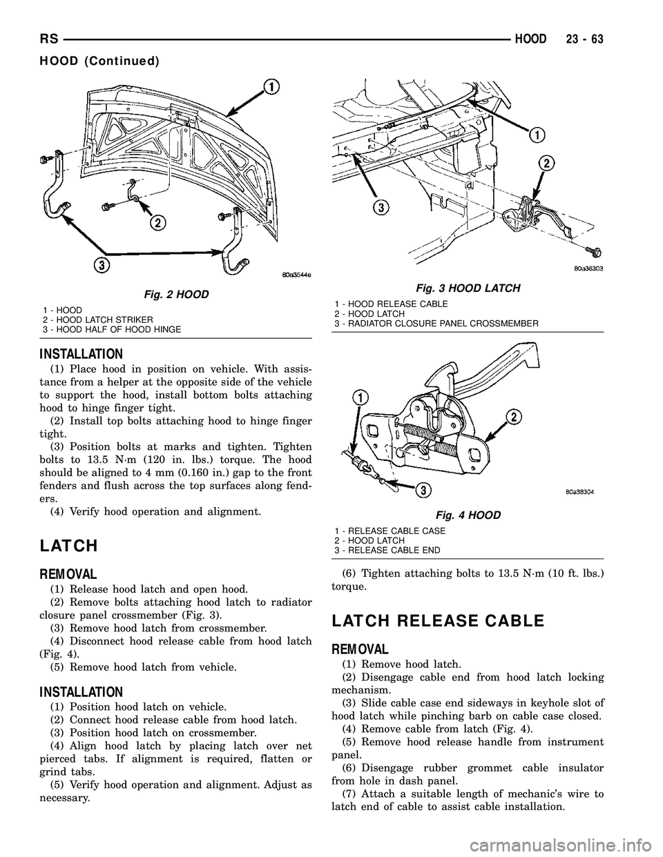
closure panel crossmember (Fig. 3).
(3) Remove hood latch from crossmember.
(4) Disconnect hood release cable from hood latch
(Fig. 4).
(5) Remove hood latch from vehicle.
INSTALLATION
(1) Position hood latch on vehicle.
(2) Connect hood release cable from hood latch.
(3) Position hood latch on crossmember.
(4) Align hood latch by placing latch over net
pierced tabs. If alignment is required, flatten or
grind tabs.
(5) Verify hood operation and alignment. Adjust as
necessary.(6) Tighten attaching bolts to 13.5 N´m (10 ft. lbs.)
torque.
LATCH RELEASE CABLE
REMOVAL
(1) Remove hood latch.
(2) Disengage cable end from hood latch locking
mechanism.
(3) Slide cable case end sideways in keyhole slot of
hood latch while pinching barb on cable case closed.
(4) Remove cable from latch (Fig. 4).
(5) Remove hood release handle from instrument
panel.
(6) Disengage rubber grommet cable insulator
from hole in dash panel.
(7) Attach a suitable length of mechanic's wire to
latch end of cable to assist cable installation.
Fig. 2 HOOD
1 - HOOD
2 - HOOD LATCH STRIKER
3 - HOOD HALF OF HOOD HINGE
Fig. 3 HOOD LATCH
1 - HOOD RELEASE CABLE
2 - HOOD LATCH
3 - RADIATOR CLOSURE PANEL CROSSMEMBER
Fig. 4 HOOD
1 - RELEASE CABLE CASE
2 - HOOD LATCH
3 - RELEASE CABLE END
RSHOOD23-63
HOOD (Continued)
Page 1843 of 2339
(8) Route cable back from latch through engine
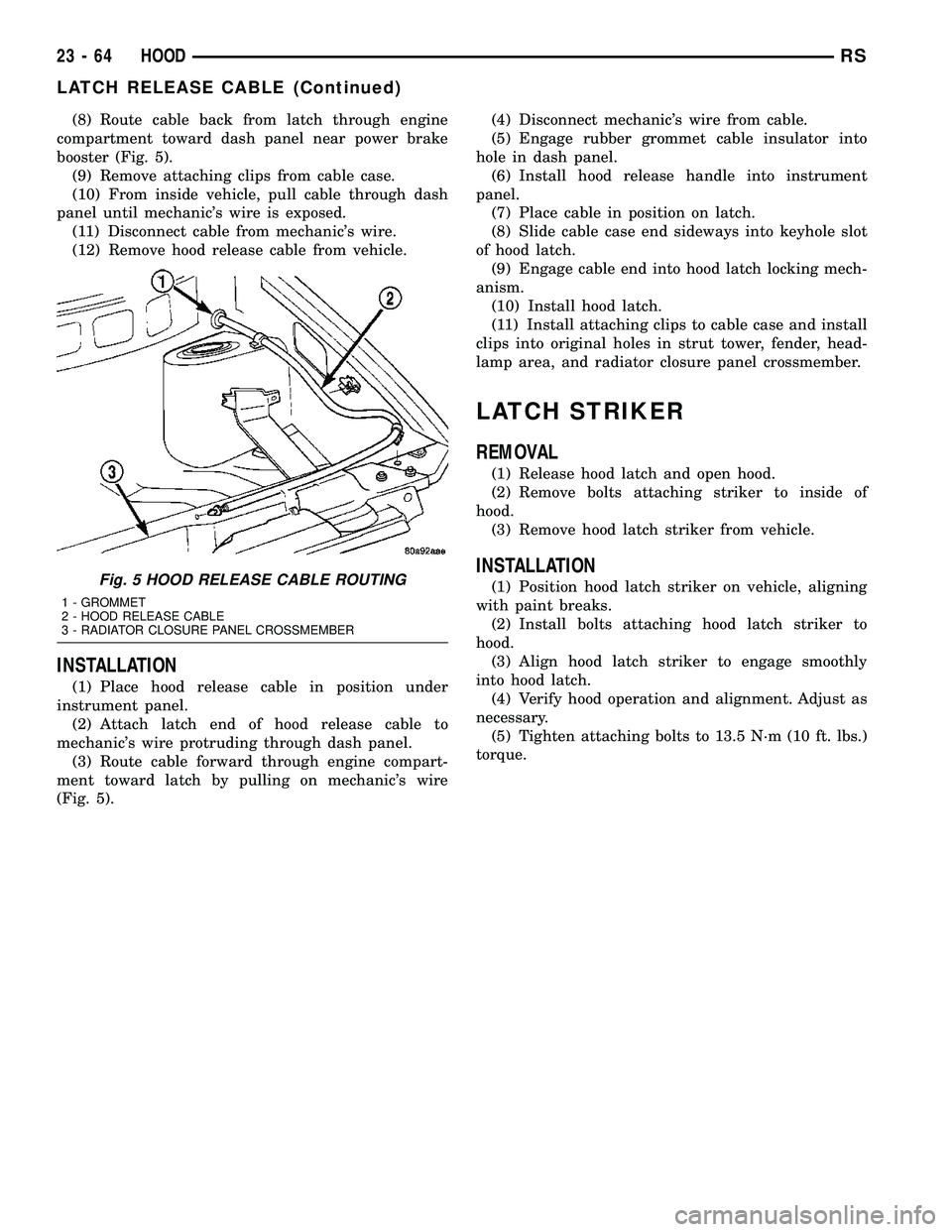
compartment toward dash panel near power brake
booster (Fig. 5).
(9) Remove attaching clips from cable case.
(10) From inside vehicle, pull cable through dash
panel until mechanic's wire is exposed.
(11) Disconnect cable from mechanic's wire.
(12) Remove hood release cable from vehicle.
INSTALLATION
(1) Place hood release cable in position under
instrument panel.
(2) Attach latch end of hood release cable to
mechanic's wire protruding through dash panel.
(3) Route cable forward through engine compart-
ment toward latch by pulling on mechanic's wire
(Fig. 5).(4) Disconnect mechanic's wire from cable.
(5) Engage rubber grommet cable insulator into
hole in dash panel.
(6) Install hood release handle into instrument
panel.
(7) Place cable in position on latch.
(8) Slide cable case end sideways into keyhole slot
of hood latch.
(9) Engage cable end into hood latch locking mech-
anism.
(10) Install hood latch.
(11) Install attaching clips to cable case and install
clips into original holes in strut tower, fender, head-
lamp area, and radiator closure panel crossmember.
LATCH STRIKER
REMOVAL
(1) Release hood latch and open hood.
(2) Remove bolts attaching striker to inside of
hood.
(3) Remove hood latch striker from vehicle.
INSTALLATION
(1) Position hood latch striker on vehicle, aligning
with paint breaks.
(2) Install bolts attaching hood latch striker to
hood.
(3) Align hood latch striker to engage smoothly
into hood latch.
(4) Verify hood operation and alignment. Adjust as
necessary.
(5) Tighten attaching bolts to 13.5 N´m (10 ft. lbs.)
torque.Fig. 5 HOOD RELEASE CABLE ROUTING
1 - GROMMET
2 - HOOD RELEASE CABLE
3 - RADIATOR CLOSURE PANEL CROSSMEMBER
23 - 64 HOODRS
LATCH RELEASE CABLE (Continued)
Page 1844 of 2339
INSTRUMENT PANEL
TABLE OF CONTENTS
page page
CLUSTER BEZEL
REMOVAL.............................65
INSTALLATION.........................65
CUP HOLDER
REMOVAL.............................65
INSTALLATION.........................65
GLOVE BOX
REMOVAL.............................66
INSTALLATION.........................66
GLOVE BOX LATCH
REMOVAL.............................66
INSTALLATION.........................66
GLOVE BOX LATCH STRIKER
REMOVAL.............................66
INSTALLATION.........................66
INSTRUMENT PANEL ASSEMBLY
REMOVAL.............................67
INSTALLATION.........................70
INSTRUMENT PANEL CENTER BEZEL
REMOVAL.............................71
INSTALLATION.........................72
INSTRUMENT PANEL RIGHT END CAP
REMOVAL.............................72INSTALLATION.........................72
INSTRUMENT PANEL TOP COVER
REMOVAL.............................72
INSTALLATION.........................72
LOWER CONSOLE
REMOVAL.............................73
INSTALLATION.........................73
LOWER INSTRUMENT PANEL
REMOVAL.............................73
INSTALLATION.........................73
LOWER STEERING COLUMN COVER
REMOVAL.............................74
INSTALLATION.........................74
BLOCKER- INFLATABLE KNEE
REMOVAL.............................75
INSTALLATION.........................75
OVER STEERING COLUMN COVER
REMOVAL.............................76
INSTALLATION.........................76
INSTRUMENT PANEL TOP PAD ASSEMBLY
REMOVAL.............................77
INSTALLATION.........................77
CLUSTER BEZEL
REMOVAL
(1) Disconnect and isolate the battery negative
cable.
(2) Remove Over Steering Column Bezel by lifting
it straight up with a firm pull.
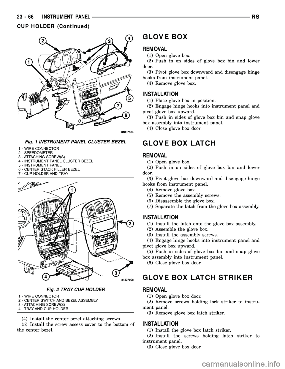
(3) Remove the four bezel attaching screws (Fig.
1).
(4) Tilt the steering column in the full down posi-
tion.
(5) Pull rearward on the cluster bezel and remove.
INSTALLATION
(1) Maneuver cluster bezel over steering column
and into position (Fig. 1).
(2) Install the four bezel attaching screws.
(3) Install the Over Steering Column Bezel by
positioning it over the retaining slots and firmly
snapping it into place.
(4) Connect the battery negative cable.
CUP HOLDER
REMOVAL
(1) Remove the screw access cover from the bottom
of the center bezel.
(2) Remove the center bezel attaching screws.
(3) Using a trim stick (special tool # C-4755) or
equivalent, gently pry out on the edge of the instru-
ment panel center bezel. Hang off to the side leaving
the accessory switches connected.
(4) Pull the cup holder assembly rearward to dis-
engage the rear guide studs from instrument panel
(Fig. 2).
(5) Remove the cup holder assembly from lower
instrument panel.
INSTALLATION
(1) Ensure the cup holder assembly is in the closed
position. The cup holder assembly must be installed
as an assembly to ensure proper track position.
(2) Place the cup holder assembly into position in
the lower instrument panel and slide into opening
until the rear guide struts snap into place (Fig. 2).
(3) Install the center bezel.
RSINSTRUMENT PANEL23-65
Page 1845 of 2339
(4) Install the center bezel attaching screws
(5) Install the screw access cover to the bottom of
the center bezel.
GLOVE BOX
REMOVAL
(1) Open glove box.
(2) Push in on sides of glove box bin and lower
door.
(3) Pivot glove box downward and disengage hinge
hooks from instrument panel.
(4) Remove glove box.
INSTALLATION
(1) Place glove box in position.
(2) Engage hinge hooks into instrument panel and
pivot glove box upward.
(3) Push in sides of glove box bin and snap glove
box assembly into instrument panel.
(4) Close glove box door.
GLOVE BOX LATCH
REMOVAL
(1) Open glove box.
(2) Push in on sides of glove box bin and lower
door.
(3) Pivot glove box downward and disengage hinge
hooks from instrument panel.
(4) Remove glove box.
(5) Remove the assembly screws.
(6) Disassemble the glove box.
(7) Separate the latch from the glove box assembly.
INSTALLATION
(1) Install the latch onto the glove box assembly.
(2) Assemble the glove box.
(3) Install the assembly screws.
(4) Engage hinge hooks into instrument panel and
pivot glove box upward.
(5) Push in sides of glove box bin and snap glove
box assembly into instrument panel.
(6) Close glove box door.
GLOVE BOX LATCH STRIKER
REMOVAL
(1) Open glove box door.
(2) Remove screws holding lock striker to instru-
ment panel.
(3) Remove glove box latch striker.
INSTALLATION
(1) Install the glove box latch striker.
(2) Install the screws holding latch striker to
instrument panel.
(3) Close glove box door.
Fig. 1 INSTRUMENT PANEL CLUSTER BEZEL
1 - WIRE CONNECTOR
2 - SPEEDOMETER
3 - ATTACHING SCREW(S)
4 - INSTRUMENT PANEL CLUSTER BEZEL
5 - INSTRUMENT PANEL
6 - CENTER STACK FILLER BEZEL
7 - CUP HOLDER AND TRAY
Fig. 2 TRAY CUP HOLDER
1 - WIRE CONNECTOR
2 - CENTER SWITCH AND BEZEL ASSEMBLY
3 - ATTACHING SCREW(S)
4 - TRAY AND CUP HOLDER
23 - 66 INSTRUMENT PANELRS
CUP HOLDER (Continued)
Page 1847 of 2339
(13) Remove the right end cover by pulling out-
board.
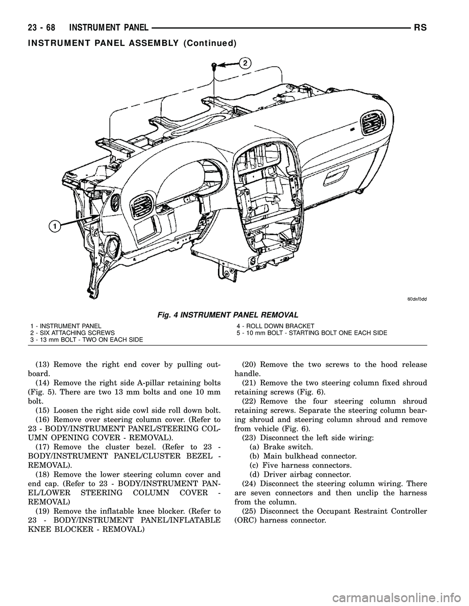
(14) Remove the right side A-pillar retaining bolts
(Fig. 5). There are two 13 mm bolts and one 10 mm
bolt.
(15) Loosen the right side cowl side roll down bolt.
(16) Remove over steering column cover. (Refer to
23 - BODY/INSTRUMENT PANEL/STEERING COL-
UMN OPENING COVER - REMOVAL).
(17) Remove the cluster bezel. (Refer to 23 -
BODY/INSTRUMENT PANEL/CLUSTER BEZEL -
REMOVAL).
(18) Remove the lower steering column cover and
end cap. (Refer to 23 - BODY/INSTRUMENT PAN-
EL/LOWER STEERING COLUMN COVER -
REMOVAL)
(19) Remove the inflatable knee blocker. (Refer to
23 - BODY/INSTRUMENT PANEL/INFLATABLE
KNEE BLOCKER - REMOVAL)(20) Remove the two screws to the hood release
handle.
(21) Remove the two steering column fixed shroud
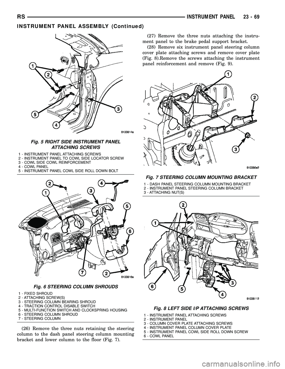
retaining screws (Fig. 6).
(22) Remove the four steering column shroud
retaining screws. Separate the steering column bear-
ing shroud and steering column shroud and remove
from vehicle (Fig. 6).
(23) Disconnect the left side wiring:
(a) Brake switch.
(b) Main bulkhead connector.
(c) Five harness connectors.
(d) Driver airbag connector.
(24) Disconnect the steering column wiring. There
are seven connectors and then unclip the harness
from the column.
(25) Disconnect the Occupant Restraint Controller
(ORC) harness connector.
Fig. 4 INSTRUMENT PANEL REMOVAL
1 - INSTRUMENT PANEL
2 - SIX ATTACHING SCREWS
3 - 13 mm BOLT - TWO ON EACH SIDE4 - ROLL DOWN BRACKET
5 - 10 mm BOLT - STARTING BOLT ONE EACH SIDE
23 - 68 INSTRUMENT PANELRS
INSTRUMENT PANEL ASSEMBLY (Continued)
Page 1848 of 2339
(26) Remove the three nuts retaining the steering
column to the dash panel steering column mounting
bracket and lower column to the floor (Fig. 7).(27) Remove the three nuts attaching the instru-
ment panel to the brake pedal support bracket.
(28) Remove six instrument panel steering column
cover plate attaching screws and remove cover plate
(Fig. 8).Remove the screws attaching the instrument
panel reinforcement and remove (Fig. 9).
Fig. 5 RIGHT SIDE INSTRUMENT PANEL
ATTACHING SCREWS
1 - INSTRUMENT PANEL ATTACHING SCREWS
2 - INSTRUMENT PANEL TO COWL SIDE LOCATOR SCREW
3 - COWL SIDE COWL REINFORCEMENT
4 - COWL PANEL
5 - INSTRUMENT PANEL COWL SIDE ROLL DOWN BOLT
Fig. 6 STEERING COLUMN SHROUDS
1 - FIXED SHROUD
2 - ATTACHING SCREW(S)
3 - STEERING COLUMN BEARING SHROUD
4 - TRACTION CONTROL DISABLE SWITCH
5 - MULTI-FUNCTION SWITCH AND CLOCKSPRING HOUSING
6 - STEERING COLUMN SHROUD
7 - STEERING COLUMN
Fig. 7 STEERING COLUMN MOUNTING BRACKET
1 - DASH PANEL STEERING COLUMN MOUNTING BRACKET
2 - INSTRUMENT PANEL STEERING COLUMN BRACKET
3 - ATTACHING NUT(S)
Fig. 8 LEFT SIDE I/P ATTACHING SCREWS
1 - INSTRUMENT PANEL ATTACHING SCREWS
2 - INSTRUMENT PANEL
3 - COLUMN COVER PLATE ATTACHING SCREWS
4 - INSTRUMENT PANEL COLUMN COVER PLATE
5 - INSTRUMENT PANEL COWL SIDE ROLL DOWN SCREW
6 - COWL PANEL
RSINSTRUMENT PANEL23-69
INSTRUMENT PANEL ASSEMBLY (Continued)