2005 CHRYSLER CARAVAN lock
[x] Cancel search: lockPage 1819 of 2339
DECKLID/HATCH/LIFTGATE/TAILGATE
TABLE OF CONTENTS
page page
EXTERIOR HANDLE
REMOVAL.............................40
INSTALLATION.........................40
HINGE
REMOVAL.............................40
INSTALLATION.........................40
LATCH
REMOVAL.............................41
INSTALLATION.........................41
LATCH STRIKER
REMOVAL.............................41
INSTALLATION.........................42
LIFTGATE
REMOVAL.............................42
INSTALLATION.........................42
LOCK CYLINDER
REMOVAL.............................42INSTALLATION.........................42
SUPPORT CYLINDER
REMOVAL.............................42
INSTALLATION.........................43
TRIM PANEL
REMOVAL.............................43
INSTALLATION.........................43
SLAM BUMPER
REMOVAL
REMOVAL - BODY SIDE................44
REMOVAL - LIFTGATE SIDE.............44
INSTALLATION
INSTALLATION - BODY SIDE............44
INSTALLATION - LIFTGATE SIDE.........44
EXTERIOR HANDLE
REMOVAL
(1) Remove liftgate trim panel. (Refer to 23 -
BODY/DECKLID/HATCH/LIFTGATE/TAILGATE/
TRIM PANEL - REMOVAL)
(2) Disconnect the exterior handle electrical con-
nectors.
(3) Remove the two outer screws and the two inner
screws.
(4) Remove the exterior handle/license plate light
assembly.
INSTALLATION
(1) Route the exterior handle electrical connector
through the door and position handle.
(2) Install the two out screws and tighten to 3 N´m
(22 in. lbs.).
(3) Install the two inner bolts and tighten to 5
N´m (40 in. lbs.).
(4) Connect the electrical connector.
(5) Install the trim panel. (Refer to 23 - BODY/
DECKLID/HATCH/LIFTGATE/TAILGATE/TRIM
PANEL - INSTALLATION)
HINGE
REMOVAL
(1) Release liftgate latch and open liftgate.
(2) Support liftgate on a suitable lifting device in
the full open position.
(3) Apply several layers of duct tape on the outside
of to roof across the gap to the lift gate to hold the
liftgate in position.
(4) Remove bolts attaching liftgate hinge to roof
header.
(5) Disconnect VTSS switch from the body har-
ness.
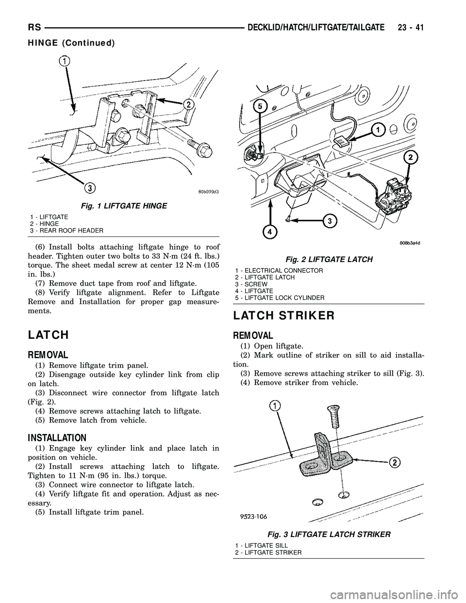
(6) Remove bolts attaching hinge to liftgate (Fig.
1).
(7) Remove hinge from vehicle.
INSTALLATION
(1) If necessary, paint replacement hinge before
installation.
(2) Place hinge in position on vehicle.
(3) Align hinge to marks on liftgate.
(4) Install bolts attaching hinge to liftgate (Fig. 1).
Tighten bolts to 33 N´m (24 ft. lbs.) torque.
(5) Align hinge to marks on roof header.
23 - 40 DECKLID/HATCH/LIFTGATE/TAILGATERS
Page 1820 of 2339
(6) Install bolts attaching liftgate hinge to roof
header. Tighten outer two bolts to 33 N´m (24 ft. lbs.)
torque. The sheet medal screw at center 12 N´m (105
in. lbs.)
(7) Remove duct tape from roof and liftgate.
(8) Verify liftgate alignment. Refer to Liftgate
Remove and Installation for proper gap measure-
ments.
LATCH
REMOVAL
(1) Remove liftgate trim panel.
(2) Disengage outside key cylinder link from clip
on latch.
(3) Disconnect wire connector from liftgate latch
(Fig. 2).
(4) Remove screws attaching latch to liftgate.
(5) Remove latch from vehicle.
INSTALLATION
(1) Engage key cylinder link and place latch in
position on vehicle.
(2) Install screws attaching latch to liftgate.
Tighten to 11 N´m (95 in. lbs.) torque.
(3) Connect wire connector to liftgate latch.
(4) Verify liftgate fit and operation. Adjust as nec-
essary.
(5) Install liftgate trim panel.
LATCH STRIKER
REMOVAL
(1) Open liftgate.
(2) Mark outline of striker on sill to aid installa-
tion.
(3) Remove screws attaching striker to sill (Fig. 3).
(4) Remove striker from vehicle.
Fig. 1 LIFTGATE HINGE
1 - LIFTGATE
2 - HINGE
3 - REAR ROOF HEADER
Fig. 2 LIFTGATE LATCH
1 - ELECTRICAL CONNECTOR
2 - LIFTGATE LATCH
3 - SCREW
4 - LIFTGATE
5 - LIFTGATE LOCK CYLINDER
Fig. 3 LIFTGATE LATCH STRIKER
1 - LIFTGATE SILL
2 - LIFTGATE STRIKER
RSDECKLID/HATCH/LIFTGATE/TAILGATE23-41
HINGE (Continued)
Page 1821 of 2339
INSTALLATION
(1) Place striker in position on vehicle.
(2) Align striker to outline mark on sill.
(3) Install screws attaching striker to sill. Tighten
screws to 28 N´m (21 ft. lbs.) torque.
(4) Verify liftgate alignment and operation.
LIFTGATE
REMOVAL
(1) Disconnect and isolate the battery negative
cable.
(2) Release liftgate latch and open liftgate.
(3) Remove liftgate upper frame molding.
(4) Remove screws attaching liftgate wire connec-
tor to rear header.
(5) Disconnect liftgate wire harness from body
wire harness.
(6) Disconnect rear window washer hose from
spray nozzle.
(7) Support liftgate on a suitable lifting device.
(8) Disconnect power liftgate link, if equipped.
(9) Remove screws attaching support cylinders to
liftgate.
(10) Remove bolts attaching liftgate hinge to roof
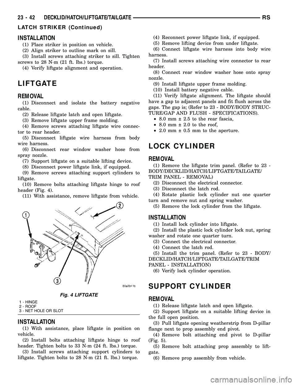
header (Fig. 4).
(11) With assistance, remove liftgate from vehicle.
INSTALLATION
(1) With assistance, place liftgate in position on
vehicle.
(2) Install bolts attaching liftgate hinge to roof
header. Tighten bolts to 33 N´m (24 ft. lbs.) torque.
(3) Install screws attaching support cylinders to
liftgate. Tighten bolts to 28 N´m (21 ft. lbs.) torque.(4) Reconnect power liftgate link, if equipped.
(5) Remove lifting device from under liftgate.
(6) Connect liftgate wire harness into body wire
harness.
(7) Install screws attaching wire connector to rear
header.
(8) Connect rear window washer hose onto spray
nozzle.
(9) Install liftgate upper frame molding.
(10) Install battery negative cable.
(11) Verify liftgate alignment. The liftgate should
have a gap to adjacent panels and fit flush across the
gaps. The gap is; (Refer to 23 - BODY/BODY STRUC-
TURE/GAP AND FLUSH - SPECIFICATIONS).
²8.0 mm 2.5 to the rear fascia,
²8.0 mm 2.0 to the roof,
²2.0 mm 0.5 mm to the aperture.
LOCK CYLINDER
REMOVAL
(1) Remove the liftgate trim panel. (Refer to 23 -
BODY/DECKLID/HATCH/LIFTGATE/TAILGATE/
TRIM PANEL - REMOVAL)
(2) Disconnect the electrical connector.
(3) Disconnect the latch rod.
(4) Rotate plastic lock cylinder nut one quarter
turn and remove nut and spring washer.
(5) Remove the lock cylinder from the liftgate.
INSTALLATION
(1) Install lock cylinder into liftgate.
(2) Install the plastic lock cylinder lock nut, spring
washer and rotate one quarter turn.
(3) Connect the electrical connector.
(4) Connect the latch rod.
(5) Install the trim panel. (Refer to 23 - BODY/
DECKLID/HATCH/LIFTGATE/TAILGATE/TRIM
PANEL - INSTALLATION)
(6) Verify lock cylinder operation.
SUPPORT CYLINDER
REMOVAL
(1) Release liftgate latch and open liftgate.
(2) Support liftgate on a suitable lifting device in
the full open position.
(3) Pull liftgate opening weatherstrip from D-pillar
flange next to prop assembly end pivot.
(4) Remove bolt attaching end pivot to D-pillar
(Fig. 5).
(5) Remove bolt attaching prop assembly to lift-
gate.
(6) Remove prop assembly from vehicle.
Fig. 4 LIFTGATE
1 - HINGE
2 - ROOF
3 - NET HOLE OR SLOT
23 - 42 DECKLID/HATCH/LIFTGATE/TAILGATERS
LATCH STRIKER (Continued)
Page 1824 of 2339
EXTERIOR
TABLE OF CONTENTS
page page
BODY SIDE MOLDINGS
REMOVAL.............................45
INSTALLATION.........................46
COWL GRILLE
REMOVAL.............................50
INSTALLATION.........................50
EXTERIOR NAME PLATES - TAPE ATTACHED
REMOVAL.............................51
INSTALLATION.........................51
EXTERIOR NAME PLATES - ADHESIVE
ATTACHED
REMOVAL.............................51
INSTALLATION.........................51
FRONT FENDER
REMOVAL.............................51
INSTALLATION.........................52
FUEL FILL DOOR
REMOVAL.............................52
INSTALLATION.........................52
FUEL FILL DOOR BLOCKER LATCH
REMOVAL.............................53
INSTALLATION.........................53
FUEL FILL DOOR BLOCKER LATCH STRIKER
REMOVAL.............................53
INSTALLATION.........................53
FUEL FILL DOOR BLOCKER LOCKOUT LINK
REMOVAL.............................54
INSTALLATION.........................54
GRILLE
DESCRIPTION.........................55REMOVAL.............................55
INSTALLATION.........................55
UPPER RADIATOR CROSSMEMBER
REMOVAL.............................56
INSTALLATION.........................56
FRONT WHEELHOUSE SPLASH SHIELD
REMOVAL.............................57
INSTALLATION.........................57
LUGGAGE RACK RISER
REMOVAL.............................57
INSTALLATION.........................58
LUGGAGE RACK CROSSBAR
REMOVAL.............................58
INSTALLATION.........................59
REAR QUARTER PANEL/FENDER AIR
EXHAUSTER
DESCRIPTION.........................59
REMOVAL.............................59
INSTALLATION.........................60
ROOF JOINT MOLDING
REMOVAL.............................60
INSTALLATION.........................60
SIDE VIEW MIRROR
REMOVAL.............................60
INSTALLATION.........................60
GLASS-OUTSIDE REARVIEW MIRROR
REMOVAL.............................61
INSTALLATION.........................61
BODY SIDE MOLDINGS
REMOVAL
Refer to (Fig. 1), (Fig. 2), (Fig. 3), (Fig. 4) or (Fig.
5)for proper location of fasteners holding the molding
to the wheelhouse lip and rocker panels.
(1) Warm the affected stick on molding and body
metal to approximately 38É C (100É F) using a suit-
able heat lamp or heat gun.(2) If equipped, remove pop rivets holding molding
edge to wheelhouse lip.
(3) Pull stick on molding from painted surface.
(4) Remove adhesive tape residue from painted
surface of vehicle. Use a 3M Scotch-BriteŸ Molding
Adhesive and Stripe Removal Disc, or equivalent, to
clean adhesive residue from painted surfaces. These
products are available from automotive paint suppli-
ers. Refer to instructions supplied with the specific
product for proper usage.
RSEXTERIOR23-45
Page 1831 of 2339
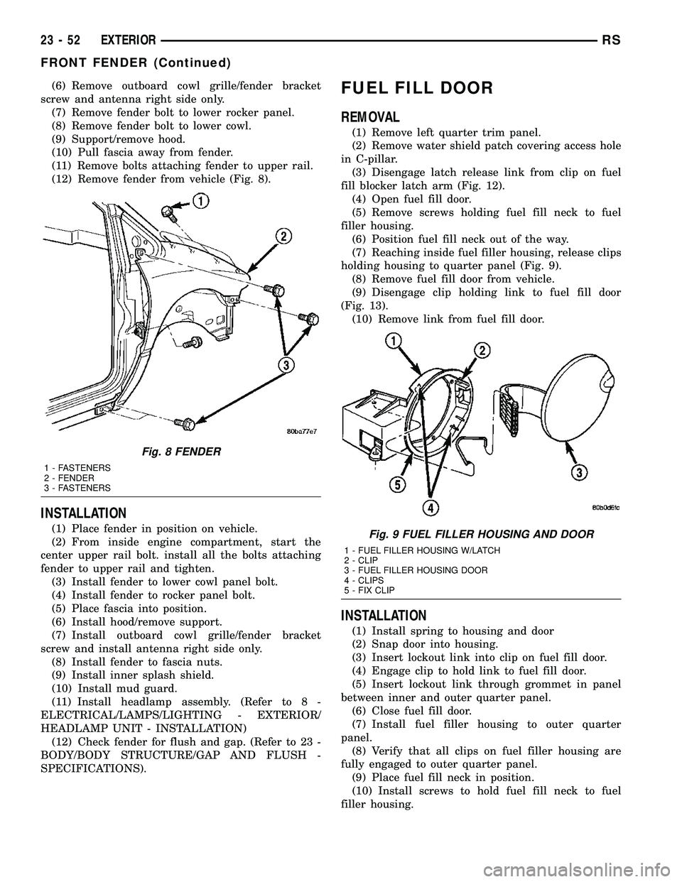
(6) Remove outboard cowl grille/fender bracket
screw and antenna right side only.
(7) Remove fender bolt to lower rocker panel.
(8) Remove fender bolt to lower cowl.
(9) Support/remove hood.
(10) Pull fascia away from fender.
(11) Remove bolts attaching fender to upper rail.
(12) Remove fender from vehicle (Fig. 8).
INSTALLATION
(1) Place fender in position on vehicle.
(2) From inside engine compartment, start the
center upper rail bolt. install all the bolts attaching
fender to upper rail and tighten.
(3) Install fender to lower cowl panel bolt.
(4) Install fender to rocker panel bolt.
(5) Place fascia into position.
(6) Install hood/remove support.
(7) Install outboard cowl grille/fender bracket
screw and install antenna right side only.
(8) Install fender to fascia nuts.
(9) Install inner splash shield.
(10) Install mud guard.
(11) Install headlamp assembly. (Refer to 8 -
ELECTRICAL/LAMPS/LIGHTING - EXTERIOR/
HEADLAMP UNIT - INSTALLATION)
(12) Check fender for flush and gap. (Refer to 23 -
BODY/BODY STRUCTURE/GAP AND FLUSH -
SPECIFICATIONS).
FUEL FILL DOOR
REMOVAL
(1) Remove left quarter trim panel.
(2) Remove water shield patch covering access hole
in C-pillar.
(3) Disengage latch release link from clip on fuel
fill blocker latch arm (Fig. 12).
(4) Open fuel fill door.
(5) Remove screws holding fuel fill neck to fuel
filler housing.
(6) Position fuel fill neck out of the way.
(7) Reaching inside fuel filler housing, release clips
holding housing to quarter panel (Fig. 9).
(8) Remove fuel fill door from vehicle.
(9) Disengage clip holding link to fuel fill door
(Fig. 13).
(10) Remove link from fuel fill door.
INSTALLATION
(1) Install spring to housing and door
(2) Snap door into housing.
(3) Insert lockout link into clip on fuel fill door.
(4) Engage clip to hold link to fuel fill door.
(5) Insert lockout link through grommet in panel
between inner and outer quarter panel.
(6) Close fuel fill door.
(7) Install fuel filler housing to outer quarter
panel.
(8) Verify that all clips on fuel filler housing are
fully engaged to outer quarter panel.
(9) Place fuel fill neck in position.
(10) Install screws to hold fuel fill neck to fuel
filler housing.
Fig. 8 FENDER
1 - FASTENERS
2 - FENDER
3 - FASTENERS
Fig. 9 FUEL FILLER HOUSING AND DOOR
1 - FUEL FILLER HOUSING W/LATCH
2 - CLIP
3 - FUEL FILLER HOUSING DOOR
4 - CLIPS
5 - FIX CLIP
23 - 52 EXTERIORRS
FRONT FENDER (Continued)
Page 1832 of 2339
(11) Engage latch release link into clip on fuel fill
blocker latch arm.
(12) Verify fuel fill blocker latch operation.
(13) Install water shield patch to cover access hole
in C-pillar.
(14) Install left quarter trim panel.
FUEL FILL DOOR BLOCKER
LATCH
REMOVAL
(1) Remove left quarter trim panel.
(2) Remove water shield patch covering access hole
in C-pillar.
(3) Disengage latch release link from clip on fuel
fill blocker latch arm (Fig. 12).
(4) Remove screws holding fuel fill blocker latch to
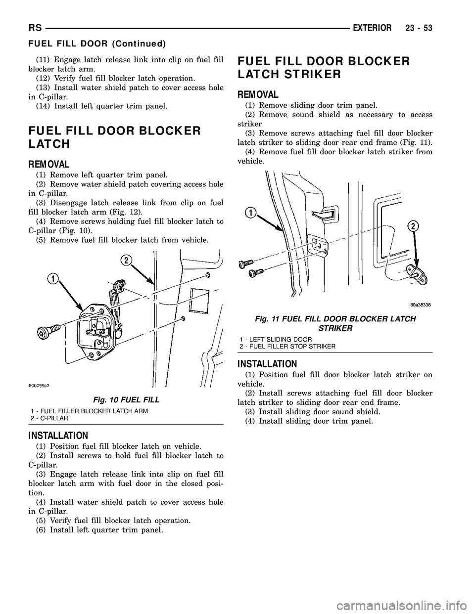
C-pillar (Fig. 10).
(5) Remove fuel fill blocker latch from vehicle.
INSTALLATION
(1) Position fuel fill blocker latch on vehicle.
(2) Install screws to hold fuel fill blocker latch to
C-pillar.
(3) Engage latch release link into clip on fuel fill
blocker latch arm with fuel door in the closed posi-
tion.
(4) Install water shield patch to cover access hole
in C-pillar.
(5) Verify fuel fill blocker latch operation.
(6) Install left quarter trim panel.
FUEL FILL DOOR BLOCKER
LATCH STRIKER
REMOVAL
(1) Remove sliding door trim panel.
(2) Remove sound shield as necessary to access
striker
(3) Remove screws attaching fuel fill door blocker
latch striker to sliding door rear end frame (Fig. 11).
(4) Remove fuel fill door blocker latch striker from
vehicle.
INSTALLATION
(1) Position fuel fill door blocker latch striker on
vehicle.
(2) Install screws attaching fuel fill door blocker
latch striker to sliding door rear end frame.
(3) Install sliding door sound shield.
(4) Install sliding door trim panel.
Fig. 10 FUEL FILL
1 - FUEL FILLER BLOCKER LATCH ARM
2 - C-PILLAR
Fig. 11 FUEL FILL DOOR BLOCKER LATCH
STRIKER
1 - LEFT SLIDING DOOR
2 - FUEL FILLER STOP STRIKER
RSEXTERIOR23-53
FUEL FILL DOOR (Continued)
Page 1833 of 2339
FUEL FILL DOOR BLOCKER
LOCKOUT LINK
REMOVAL
(1) Remove left quarter trim panel.
(2) Remove water shield patch covering access hole
in C-pillar.
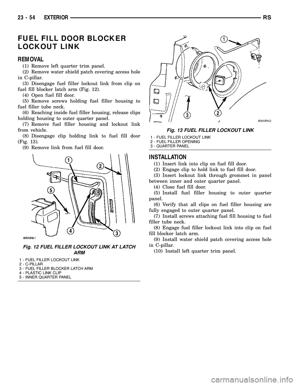
(3) Disengage fuel filler lockout link from clip on
fuel fill blocker latch arm (Fig. 12).
(4) Open fuel fill door.
(5) Remove screws holding fuel filler housing to
fuel filler tube neck.
(6) Reaching inside fuel filler housing, release clips
holding housing to outer quarter panel.
(7) Remove fuel filler housing and lockout link
from vehicle.
(8) Disengage clip holding link to fuel fill door
(Fig. 13).
(9) Remove link from fuel fill door.
INSTALLATION
(1) Insert link into clip on fuel fill door.
(2) Engage clip to hold link to fuel fill door.
(3) Insert lockout link through grommet in panel
between inner and outer quarter panel.
(4) Close fuel fill door.
(5) Install fuel filler housing to outer quarter
panel.
(6) Verify that all clips on fuel filler housing are
fully engaged to outer quarter panel.
(7) Install screws attaching fuel fill housing to fuel
filler tube neck.
(8) Engage fuel filler lockout link into clip on fuel
fill blocker latch arm.
(9) Install water shield patch covering access hole
in C-pillar.
(10) Install left quarter trim panel.
Fig. 12 FUEL FILLER LOCKOUT LINK AT LATCH
ARM
1 - FUEL FILLER LOCKOUT LINK
2 - C-PILLAR
3 - FUEL FILLER BLOCKER LATCH ARM
4 - PLASTIC LINK CLIP
5 - INNER QUARTER PANEL
Fig. 13 FUEL FILLER LOCKOUT LINK
1 - FUEL FILLER LOCKOUT LINK
2 - FUEL FILLER OPENING
3 - QUARTER PANEL
23 - 54 EXTERIORRS
Page 1836 of 2339
(2) Insert ends of crossmember between layered
metal sections of radiator closure panel at each side
of radiator.
(3) Align with paint breaks around bolt heads.
(4) Install bolts attaching ends of crossmember to
radiator closure panel (Fig. 16). Tighten bolts to 19
N´m (14 ft. lbs.) torque.
(5) Install bolts attaching radiator isolators to
crossmember.
(6) Install screw attaching coolant recovery bottle
to crossmember.
(7) Install bolt attaching air cleaner housing to
crossmember.
(8) Install engine air inlet resonator.
(9) Install hood prop rod.
(10) Align hood latch by placing latch over net
pierce tabs. If alignment is required, flatten tabs.
(11) Install bolts attaching hood latch to cross-
member and clip cable. Tighten bolts to 13.5 N´m (10
ft. lbs.) torque.
(12) Install radiator sight shield.
(13) Verify hood latch operation and hood align-
ment.
FRONT WHEELHOUSE
SPLASH SHIELD
REMOVAL
(1) Hoist and support vehicle on safety stands.
(Refer to LUBRICATION & MAINTENANCE/HOIST-
ING - STANDARD PROCEDURE).
(2) Remove front wheel.
(3) Remove push pin fasteners attaching splash
shield to frame rail forward of suspension.
(4) Remove push pin fasteners attaching splash
shield to frame rail rearward of suspension.
(5) Remove screws attaching wheelhouse splash
shield to front fender and front bumper fascia.
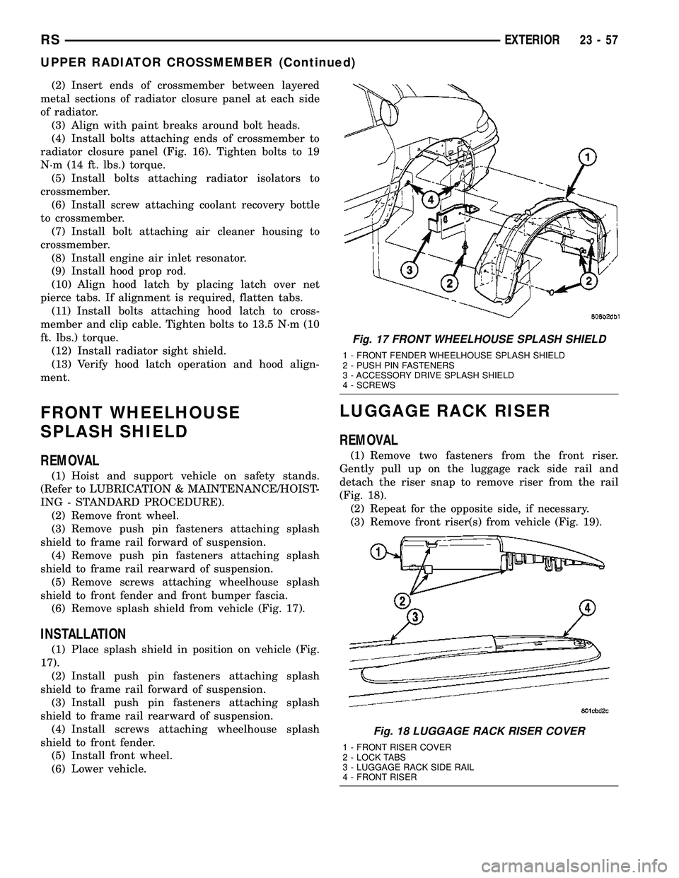
(6) Remove splash shield from vehicle (Fig. 17).
INSTALLATION
(1) Place splash shield in position on vehicle (Fig.
17).
(2) Install push pin fasteners attaching splash
shield to frame rail forward of suspension.
(3) Install push pin fasteners attaching splash
shield to frame rail rearward of suspension.
(4) Install screws attaching wheelhouse splash
shield to front fender.
(5) Install front wheel.
(6) Lower vehicle.
LUGGAGE RACK RISER
REMOVAL
(1) Remove two fasteners from the front riser.
Gently pull up on the luggage rack side rail and
detach the riser snap to remove riser from the rail
(Fig. 18).
(2) Repeat for the opposite side, if necessary.
(3) Remove front riser(s) from vehicle (Fig. 19).
Fig. 17 FRONT WHEELHOUSE SPLASH SHIELD
1 - FRONT FENDER WHEELHOUSE SPLASH SHIELD
2 - PUSH PIN FASTENERS
3 - ACCESSORY DRIVE SPLASH SHIELD
4 - SCREWS
Fig. 18 LUGGAGE RACK RISER COVER
1 - FRONT RISER COVER
2 - LOCK TABS
3 - LUGGAGE RACK SIDE RAIL
4 - FRONT RISER
RSEXTERIOR23-57
UPPER RADIATOR CROSSMEMBER (Continued)