2005 CHRYSLER CARAVAN instrument cluster
[x] Cancel search: instrument clusterPage 880 of 2339

8W-52 TURN SIGNALS
Component Page
Body Control Module........... 8W-52-2, 3, 4, 5
Fuse 24............................ 8W-52-5
G102.............................. 8W-52-2
G200............................ 8W-52-2, 3
G302.............................. 8W-52-4
Instrument Cluster................... 8W-52-5
Instrument Panel Switch Bank....... 8W-52-2, 3
Integrated Power Module.......... 8W-52-2, 3, 5
Left Front Park/Turn Signal Lamp....... 8W-52-2Component Page
Left Rear Lamp Assembly............. 8W-52-4
Left Repeater Lamp.................. 8W-52-5
Left Turn Signal Lamp................ 8W-52-3
Multi-Function Switch.............. 8W-52-2, 3
Right Front Park/Turn Signal Lamp..... 8W-52-2
Right Rear Lamp Assembly............ 8W-52-4
Right Repeater Lamp................. 8W-52-5
Right Turn Signal Lamp............... 8W-52-3
Trailer Tow Connector................ 8W-52-4
RS8W-52 TURN SIGNALS8W-52-1
Page 972 of 2339

Component Page
Evaporator Temperature Sensor........ 8W-80-70
Floor Console Lamp................. 8W-80-70
Floor Console Power Outlet (Export).... 8W-80-70
Front Blower Module C1 (ATC)........ 8W-80-71
Front Blower Module C2 (ATC)........ 8W-80-71
Front Cigar Lighter................. 8W-80-71
Front Control Module................ 8W-80-72
Front Intrusion Sensor (United
Kingdom)....................... 8W-80-73
Front Reading Lamps/Switch.......... 8W-80-73
Fuel Heater (Diesel)................. 8W-80-73
Fuel Injector No. 1 (2.4L/3.3L/3.8L)..... 8W-80-73
Fuel Injector No. 1 (Diesel)............ 8W-80-73
Fuel Injector No. 2 (2.4L/3.3L/3.8L)..... 8W-80-74
Fuel Injector No. 2 (Diesel)............ 8W-80-74
Fuel Injector No. 3 (2.4L/3.3L/3.8L)..... 8W-80-74
Fuel Injector No. 3 (Diesel)............ 8W-80-74
Fuel Injector No. 4 (2.4L/3.3L/3.8L)..... 8W-80-75
Fuel Injector No. 4 (Diesel)............ 8W-80-75
Fuel Injector No. 5 (3.3L/3.8L)......... 8W-80-75
Fuel Injector No. 6 (3.3L/3.8L)......... 8W-80-75
Fuel Pressure Sensor (Diesel).......... 8W-80-76
Fuel Pressure Solenoid (Diesel)........ 8W-80-76
Fuel Pump Module.................. 8W-80-76
Generator......................... 8W-80-76
Glow Plug Relay (Diesel)............. 8W-80-77
Hands Free Module C1............... 8W-80-77
Hands Free Module C2............... 8W-80-77
Hands Free Module C3............... 8W-80-78
Headlamp Switch................... 8W-80-78
Headlamp Washer Pump Motor (Export) . 8W-80-78
High Note Horn.................... 8W-80-79
Hood Ajar Switch (Export)............ 8W-80-79
Idle Air Control Motor (Gas)........... 8W-80-79
Ignition Coil (2.4L).................. 8W-80-79
Ignition Coil (3.3L/3.8L).............. 8W-80-80
Ignition Switch..................... 8W-80-80
Inlet Air Temperature Sensor.......... 8W-80-80
Input Speed Sensor................. 8W-80-80
Instrument Cluster.................. 8W-80-81
Instrument Panel Switch Bank
(Except Heated Seats)............. 8W-80-81
Instrument Panel Switch Bank
(Heated Seats)................... 8W-80-81
Integrated Power Module C1.......... 8W-80-82
Integrated Power Module C2.......... 8W-80-82
Integrated Power Module C3.......... 8W-80-83
Integrated Power Module C4.......... 8W-80-83
Integrated Power Module C5.......... 8W-80-84
Integrated Power Module C6.......... 8W-80-84
Integrated Power Module C7.......... 8W-80-84
Integrated Power Module C8.......... 8W-80-85
Integrated Power Module C9.......... 8W-80-85
Knock Sensor (Except Export)......... 8W-80-85Component Page
Left B-Pillar Switch (Power Sliding
Door).......................... 8W-80-86
Left Cinch/Release Motor (Power Sliding
Door).......................... 8W-80-86
Left Curtain Airbag Squib............ 8W-80-86
Left Cylinder Lock Switch (Export)..... 8W-80-86
Left Door Speaker.................. 8W-80-87
Left Fog Lamp..................... 8W-80-87
Left Front Door Ajar Switch (Base)..... 8W-80-87
Left Front Door Lock Motor/Ajar Switch
(Except Base).................... 8W-80-87
Left Front Impact Sensor (Export)...... 8W-80-87
Left Front Impact Sensor (Except
Export)......................... 8W-80-88
Left Front Park/Turn Signal Lamp...... 8W-80-88
Left Front Wheel Speed Sensor........ 8W-80-88
Left Full Open Switch (Power Sliding
Door).......................... 8W-80-88
Left Headlamp (Caravan/Voyager Except
Export)......................... 8W-80-89
Left Headlamp (Town And Country)..... 8W-80-89
Left Headlamp Leveling Motor (Export) . . 8W-80-89
Left High Beam Lamp (Export)........ 8W-80-89
Left Instrument Panel Speaker........ 8W-80-90
Left Liftgate Flood Lamp (Export)...... 8W-80-90
Left Low Beam Lamp (Export)......... 8W-80-90
Left Mid Reading Lamp (Premium/
Luxury)........................ 8W-80-90
Left Park Lamp (Export)............. 8W-80-91
Left Power Mirror................... 8W-80-91
Left Rear Lamp Assembly............ 8W-80-91
Left Rear Pillar Speaker (Highline
Audio).......................... 8W-80-92
Left Rear Reading Lamp (Luxury)...... 8W-80-92
Left Rear Speaker.................. 8W-80-92
Left Rear Vent Motor................ 8W-80-92
Left Rear Wheel Speed Sensor......... 8W-80-93
Left Remote Radio Switch............ 8W-80-93
Left Repeater Lamp (Export).......... 8W-80-93
Left Side Impact Sensor 1 (Export)..... 8W-80-93
Left Side Impact Sensor 1 (Except
Export)......................... 8W-80-94
Left Side Impact Sensor 2............ 8W-80-94
Left Side Impact Sensor 3............ 8W-80-94
Left Sliding Door Control Module C1
(Power Sliding Door).............. 8W-80-94
Left Sliding Door Control Module C2
(Power Sliding Door).............. 8W-80-95
Left Sliding Door Latch Sensing Switch
(Power Sliding Door).............. 8W-80-95
Left Sliding Door Lock Motor (Power Sliding
Door).......................... 8W-80-95
Left Sliding Door Lock Motor/Ajar Switch
(Manual Sliding Door)............. 8W-80-96
RS8W-80 CONNECTOR PIN-OUTS8W-80-3
Page 984 of 2339

BODY CONTROL MODULE C4 - BLACK/GRAY 34 WAY
CAV CIRCUIT FUNCTION
1- -
2 E12 20OR/GY PANEL LAMPS DRIVER
3 E19 20OR/BR (AUTOMATIC HEAD-
LAMPS)HEADLAMP SWITCH DIMMER SIGNAL
4- -
5 G150 22VT/BR INSTRUMENT CLUSTER WAKE UP SENSE
6- -
7 P162 20LG/DG (EXPORT) PASSENGER FOLDING MIRROR RELAY CONTROL
8- -
9 L161 20WT/LG LEFT TURN INDICATOR DRIVER
10 F504 20GY/PK FUSED IGNITION SWITCH OUTPUT (RUN)
11 E14 20OR/TN PANEL LAMPS DRIVER
12 E13 20OR/WT PANEL LAMPS DRIVER
13 X920 22GY/OR (REMOTE AUDIO) RADIO CONTROL MUX RETURN
14 G900 20VT/DB IGNITION SWITCH SENSE RETURN
15 - -
16 - -
17 L160 20WT/TN RIGHT TURN INDICATOR DRIVER
18 - -
19 - -
20 - -
21 - -
22 G902 22VT/LB MULTI-FUNCTION SWITCH MUX RETURN
23 - -
24 - -
25 - -
26 - -
27 - -
28 - -
29 - -
30 - -
31 - -
32 B27 20DG/WT (TRACTION CONTROL) TRACTION CONTROL SWITCH SENSE
33 P136 20TN/YL (EXPORT) FOLDING MIRROR SWITCH SENSE
34 G26 22VT/OR CHIME DRIVER
RS8W-80 CONNECTOR PIN-OUTS8W-80-15
Page 1050 of 2339
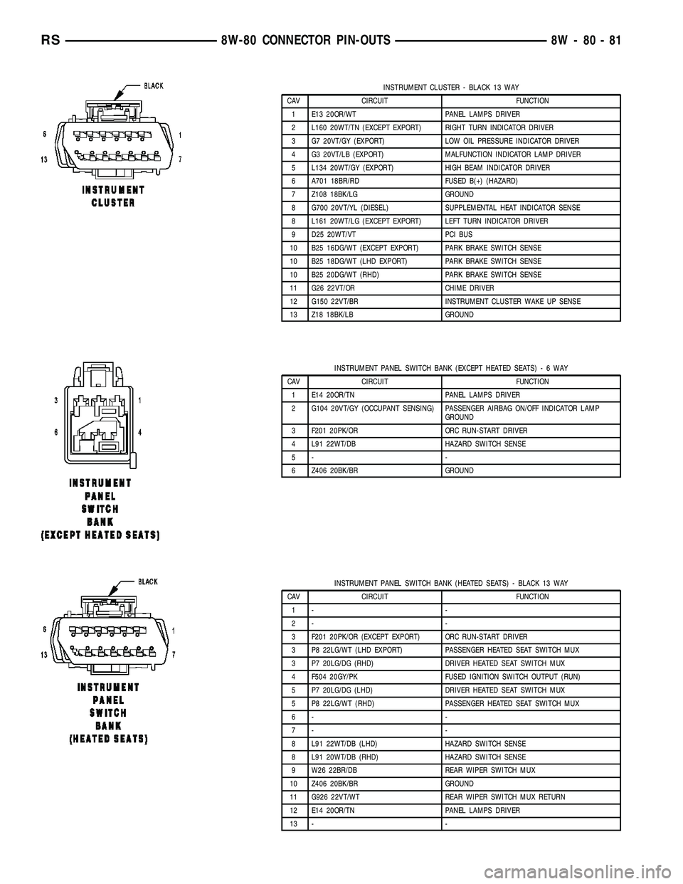
INSTRUMENT CLUSTER - BLACK 13 WAY
CAV CIRCUIT FUNCTION
1 E13 20OR/WT PANEL LAMPS DRIVER
2 L160 20WT/TN (EXCEPT EXPORT) RIGHT TURN INDICATOR DRIVER
3 G7 20VT/GY (EXPORT) LOW OIL PRESSURE INDICATOR DRIVER
4 G3 20VT/LB (EXPORT) MALFUNCTION INDICATOR LAMP DRIVER
5 L134 20WT/GY (EXPORT) HIGH BEAM INDICATOR DRIVER
6 A701 18BR/RD FUSED B(+) (HAZARD)
7 Z108 18BK/LG GROUND
8 G700 20VT/YL (DIESEL) SUPPLEMENTAL HEAT INDICATOR SENSE
8 L161 20WT/LG (EXCEPT EXPORT) LEFT TURN INDICATOR DRIVER
9 D25 20WT/VT PCI BUS
10 B25 16DG/WT (EXCEPT EXPORT) PARK BRAKE SWITCH SENSE
10 B25 18DG/WT (LHD EXPORT) PARK BRAKE SWITCH SENSE
10 B25 20DG/WT (RHD) PARK BRAKE SWITCH SENSE
11 G26 22VT/OR CHIME DRIVER
12 G150 22VT/BR INSTRUMENT CLUSTER WAKE UP SENSE
13 Z18 18BK/LB GROUND
INSTRUMENT PANEL SWITCH BANK (EXCEPT HEATED SEATS)-6WAY
CAV CIRCUIT FUNCTION
1 E14 20OR/TN PANEL LAMPS DRIVER
2 G104 20VT/GY (OCCUPANT SENSING) PASSENGER AIRBAG ON/OFF INDICATOR LAMP
GROUND
3 F201 20PK/OR ORC RUN-START DRIVER
4 L91 22WT/DB HAZARD SWITCH SENSE
5- -
6 Z406 20BK/BR GROUND
INSTRUMENT PANEL SWITCH BANK (HEATED SEATS) - BLACK 13 WAY
CAV CIRCUIT FUNCTION
1- -
2- -
3 F201 20PK/OR (EXCEPT EXPORT) ORC RUN-START DRIVER
3 P8 22LG/WT (LHD EXPORT) PASSENGER HEATED SEAT SWITCH MUX
3 P7 20LG/DG (RHD) DRIVER HEATED SEAT SWITCH MUX
4 F504 20GY/PK FUSED IGNITION SWITCH OUTPUT (RUN)
5 P7 20LG/DG (LHD) DRIVER HEATED SEAT SWITCH MUX
5 P8 22LG/WT (RHD) PASSENGER HEATED SEAT SWITCH MUX
6- -
7- -
8 L91 22WT/DB (LHD) HAZARD SWITCH SENSE
8 L91 20WT/DB (RHD) HAZARD SWITCH SENSE
9 W26 22BR/DB REAR WIPER SWITCH MUX
10 Z406 20BK/BR GROUND
11 G926 22VT/WT REAR WIPER SWITCH MUX RETURN
12 E14 20OR/TN PANEL LAMPS DRIVER
13 - -
RS8W-80 CONNECTOR PIN-OUTS8W-80-81
Page 1119 of 2339
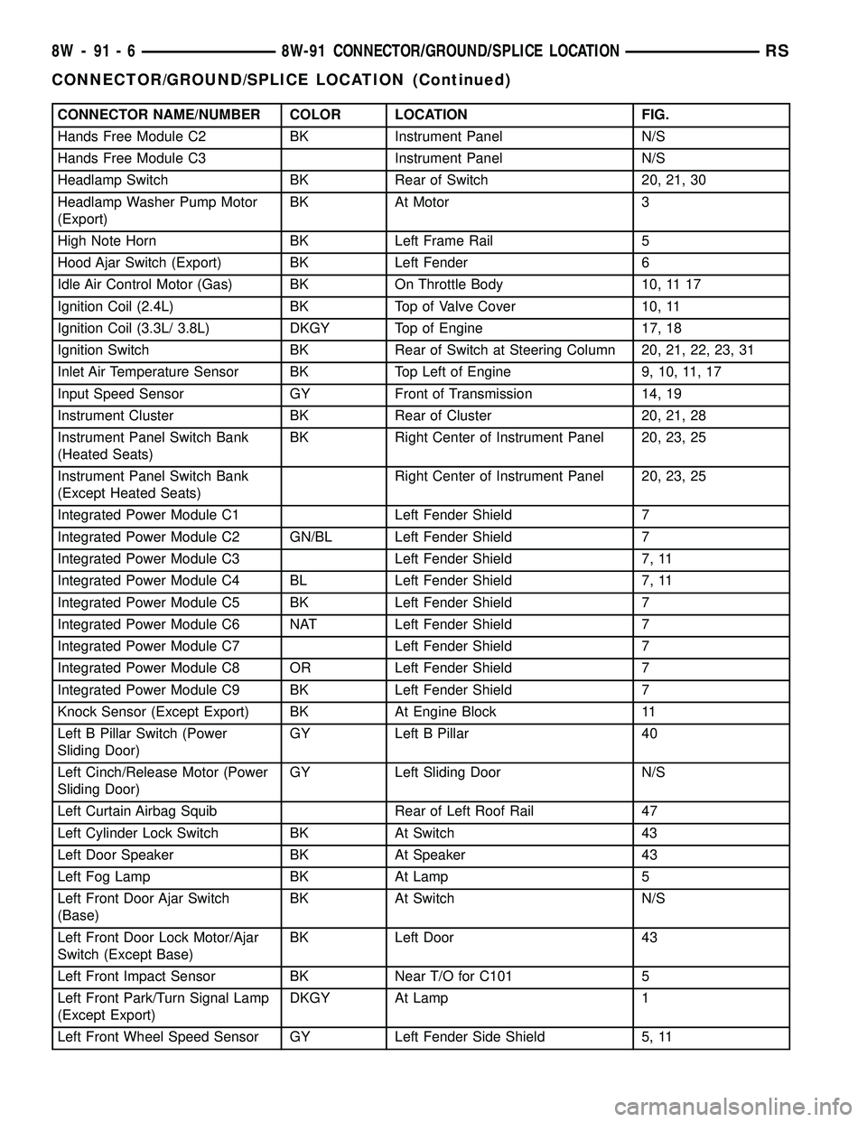
CONNECTOR NAME/NUMBER COLOR LOCATION FIG.
Hands Free Module C2 BK Instrument Panel N/S
Hands Free Module C3 Instrument Panel N/S
Headlamp Switch BK Rear of Switch 20, 21, 30
Headlamp Washer Pump Motor
(Export)BK At Motor 3
High Note Horn BK Left Frame Rail 5
Hood Ajar Switch (Export) BK Left Fender 6
Idle Air Control Motor (Gas) BK On Throttle Body 10, 11 17
Ignition Coil (2.4L) BK Top of Valve Cover 10, 11
Ignition Coil (3.3L/ 3.8L) DKGY Top of Engine 17, 18
Ignition Switch BK Rear of Switch at Steering Column 20, 21, 22, 23, 31
Inlet Air Temperature Sensor BK Top Left of Engine 9, 10, 11, 17
Input Speed Sensor GY Front of Transmission 14, 19
Instrument Cluster BK Rear of Cluster 20, 21, 28
Instrument Panel Switch Bank
(Heated Seats)BK Right Center of Instrument Panel 20, 23, 25
Instrument Panel Switch Bank
(Except Heated Seats)Right Center of Instrument Panel 20, 23, 25
Integrated Power Module C1 Left Fender Shield 7
Integrated Power Module C2 GN/BL Left Fender Shield 7
Integrated Power Module C3 Left Fender Shield 7, 11
Integrated Power Module C4 BL Left Fender Shield 7, 11
Integrated Power Module C5 BK Left Fender Shield 7
Integrated Power Module C6 NAT Left Fender Shield 7
Integrated Power Module C7 Left Fender Shield 7
Integrated Power Module C8 OR Left Fender Shield 7
Integrated Power Module C9 BK Left Fender Shield 7
Knock Sensor (Except Export) BK At Engine Block 11
Left B Pillar Switch (Power
Sliding Door)GY Left B Pillar 40
Left Cinch/Release Motor (Power
Sliding Door)GY Left Sliding Door N/S
Left Curtain Airbag Squib Rear of Left Roof Rail 47
Left Cylinder Lock Switch BK At Switch 43
Left Door Speaker BK At Speaker 43
Left Fog Lamp BK At Lamp 5
Left Front Door Ajar Switch
(Base)BK At Switch N/S
Left Front Door Lock Motor/Ajar
Switch (Except Base)BK Left Door 43
Left Front Impact Sensor BK Near T/O for C101 5
Left Front Park/Turn Signal Lamp
(Except Export)DKGY At Lamp 1
Left Front Wheel Speed Sensor GY Left Fender Side Shield 5, 11
8W - 91 - 6 8W-91 CONNECTOR/GROUND/SPLICE LOCATIONRS
CONNECTOR/GROUND/SPLICE LOCATION (Continued)
Page 1127 of 2339
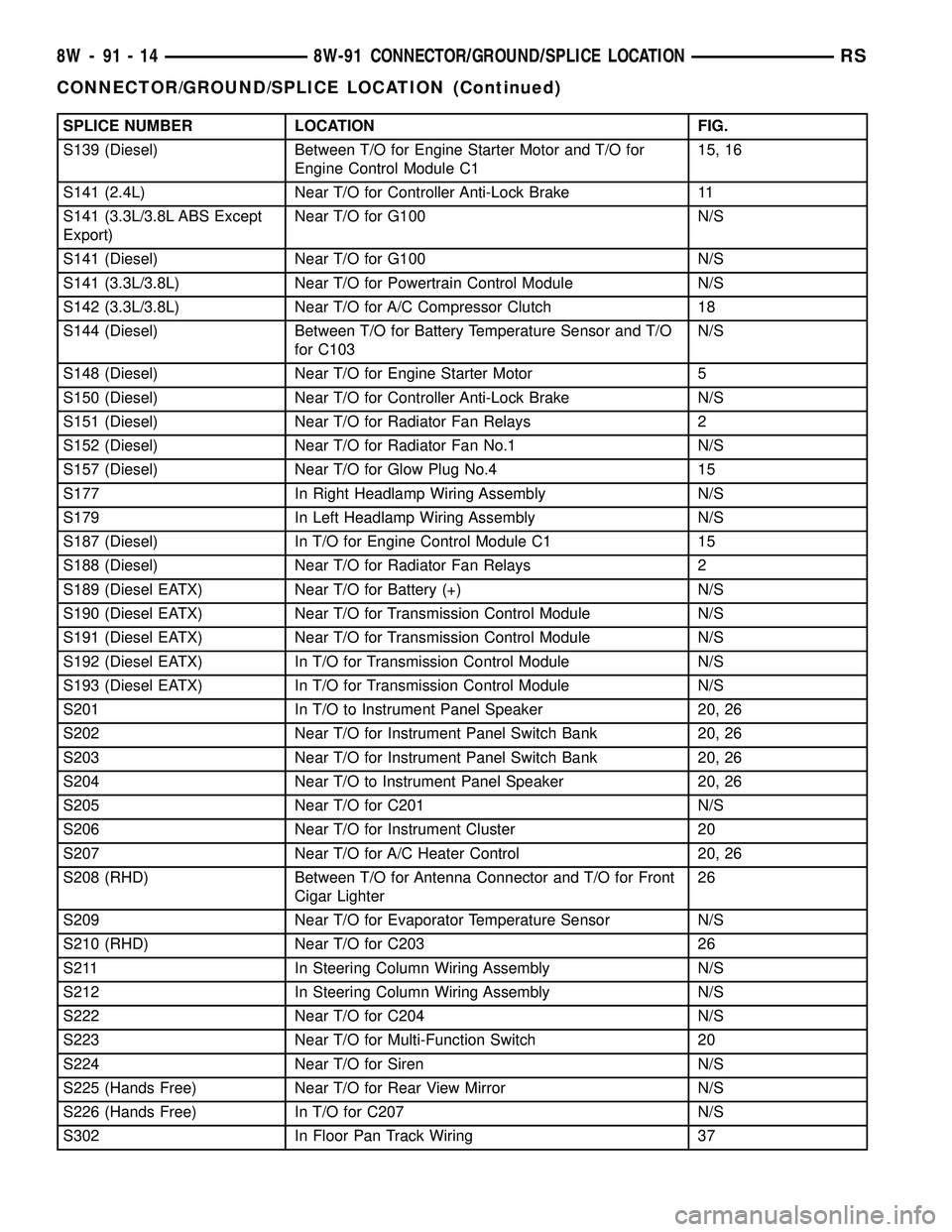
SPLICE NUMBER LOCATION FIG.
S139 (Diesel) Between T/O for Engine Starter Motor and T/O for
Engine Control Module C115, 16
S141 (2.4L) Near T/O for Controller Anti-Lock Brake 11
S141 (3.3L/3.8L ABS Except
Export)Near T/O for G100 N/S
S141 (Diesel) Near T/O for G100 N/S
S141 (3.3L/3.8L) Near T/O for Powertrain Control Module N/S
S142 (3.3L/3.8L) Near T/O for A/C Compressor Clutch 18
S144 (Diesel) Between T/O for Battery Temperature Sensor and T/O
for C103N/S
S148 (Diesel) Near T/O for Engine Starter Motor 5
S150 (Diesel) Near T/O for Controller Anti-Lock Brake N/S
S151 (Diesel) Near T/O for Radiator Fan Relays 2
S152 (Diesel) Near T/O for Radiator Fan No.1 N/S
S157 (Diesel) Near T/O for Glow Plug No.4 15
S177 In Right Headlamp Wiring Assembly N/S
S179 In Left Headlamp Wiring Assembly N/S
S187 (Diesel) In T/O for Engine Control Module C1 15
S188 (Diesel) Near T/O for Radiator Fan Relays 2
S189 (Diesel EATX) Near T/O for Battery (+) N/S
S190 (Diesel EATX) Near T/O for Transmission Control Module N/S
S191 (Diesel EATX) Near T/O for Transmission Control Module N/S
S192 (Diesel EATX) In T/O for Transmission Control Module N/S
S193 (Diesel EATX) In T/O for Transmission Control Module N/S
S201 In T/O to Instrument Panel Speaker 20, 26
S202 Near T/O for Instrument Panel Switch Bank 20, 26
S203 Near T/O for Instrument Panel Switch Bank 20, 26
S204 Near T/O to Instrument Panel Speaker 20, 26
S205 Near T/O for C201 N/S
S206 Near T/O for Instrument Cluster 20
S207 Near T/O for A/C Heater Control 20, 26
S208 (RHD) Between T/O for Antenna Connector and T/O for Front
Cigar Lighter26
S209 Near T/O for Evaporator Temperature Sensor N/S
S210 (RHD) Near T/O for C203 26
S211 In Steering Column Wiring Assembly N/S
S212 In Steering Column Wiring Assembly N/S
S222 Near T/O for C204 N/S
S223 Near T/O for Multi-Function Switch 20
S224 Near T/O for Siren N/S
S225 (Hands Free) Near T/O for Rear View Mirror N/S
S226 (Hands Free) In T/O for C207 N/S
S302 In Floor Pan Track Wiring 37
8W - 91 - 14 8W-91 CONNECTOR/GROUND/SPLICE LOCATIONRS
CONNECTOR/GROUND/SPLICE LOCATION (Continued)
Page 1321 of 2339
INSTALLATION
(1) Clean relief valve, spring and bore.
NOTE: Lubricate relief valve with clean engine oil
before installing.
(2) Install relief valve and spring into housing.
(3) Install new retainer cap until flush with seal-
ing surface.
(4) Install oil pan (Refer to 9 - ENGINE/LUBRI-
CATION/OIL PAN - INSTALLATION).
(5) Fill crankcase with proper oil to correct level.
OIL PRESSURE SWITCH
DESCRIPTION
The engine oil pressure switch is located on the
lower left front side of the engine. It screws into the
oil filter adapter. The normally closed switch provides
an input through a single wire to the low pressure
indicator light on the instrument cluster.
OPERATION
The oil pressure switch provides a ground for the
instrument cluster low oil pressure indicator light.
The switch receives oil pressure input from the
engine main oil gallery. When engine oil pressure is
greater than 27.5 Kpa (4 psi), the switch contacts
open, providing a open circuit to the low pressure
indicator light. For wiring circuits and diagnostic
information, (Refer to Appropriate Wiring/Diagnostic
Information).
REMOVAL
(1) Raise vehicle on hoist.
(2) Disconnect electrical connector from switch.
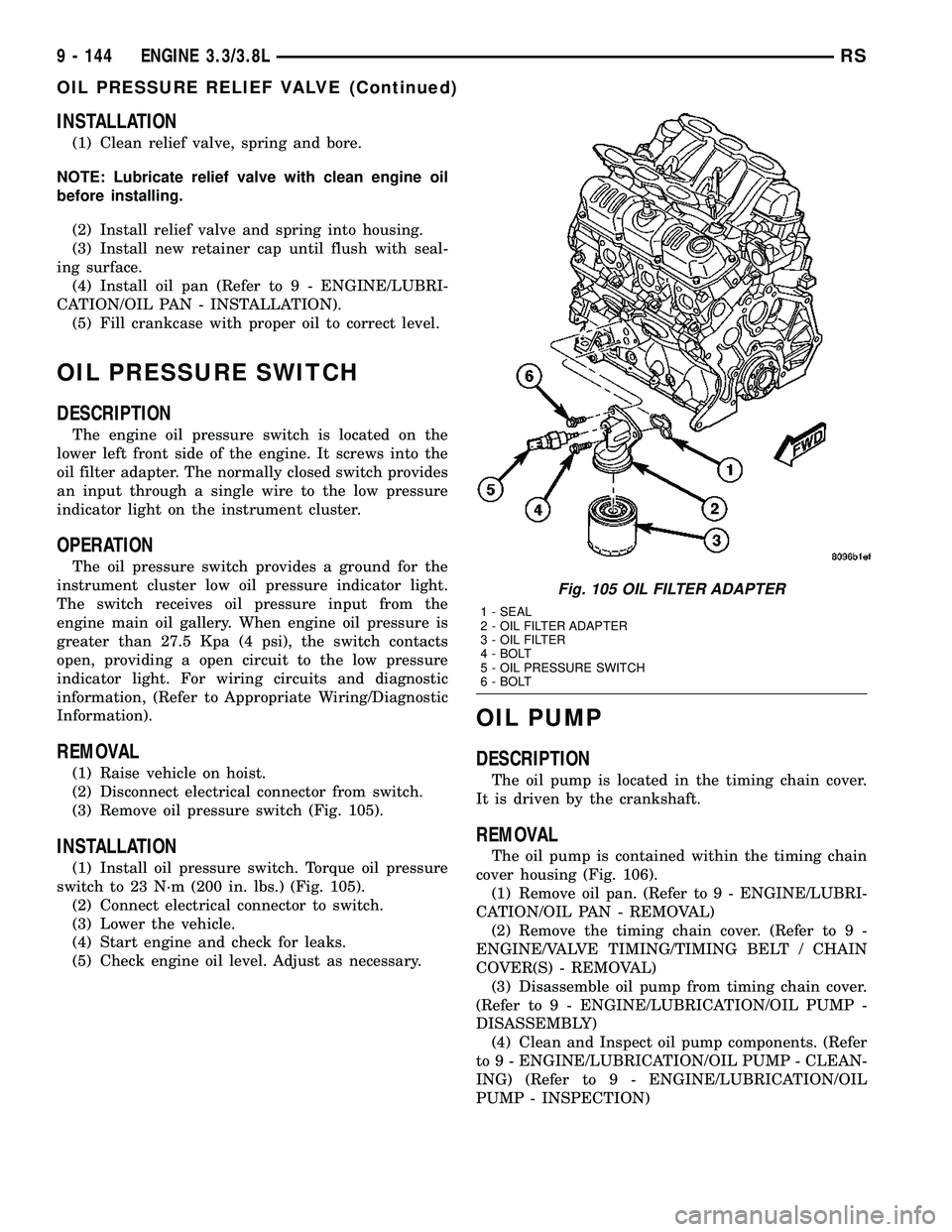
(3) Remove oil pressure switch (Fig. 105).
INSTALLATION
(1) Install oil pressure switch. Torque oil pressure
switch to 23 N´m (200 in. lbs.) (Fig. 105).
(2) Connect electrical connector to switch.
(3) Lower the vehicle.
(4) Start engine and check for leaks.
(5) Check engine oil level. Adjust as necessary.
OIL PUMP
DESCRIPTION
The oil pump is located in the timing chain cover.
It is driven by the crankshaft.
REMOVAL
The oil pump is contained within the timing chain
cover housing (Fig. 106).
(1) Remove oil pan. (Refer to 9 - ENGINE/LUBRI-
CATION/OIL PAN - REMOVAL)
(2) Remove the timing chain cover. (Refer to 9 -
ENGINE/VALVE TIMING/TIMING BELT / CHAIN
COVER(S) - REMOVAL)
(3) Disassemble oil pump from timing chain cover.
(Refer to 9 - ENGINE/LUBRICATION/OIL PUMP -
DISASSEMBLY)
(4) Clean and Inspect oil pump components. (Refer
to 9 - ENGINE/LUBRICATION/OIL PUMP - CLEAN-
ING) (Refer to 9 - ENGINE/LUBRICATION/OIL
PUMP - INSPECTION)
Fig. 105 OIL FILTER ADAPTER
1 - SEAL
2 - OIL FILTER ADAPTER
3 - OIL FILTER
4 - BOLT
5 - OIL PRESSURE SWITCH
6 - BOLT
9 - 144 ENGINE 3.3/3.8LRS
OIL PRESSURE RELIEF VALVE (Continued)
Page 1420 of 2339
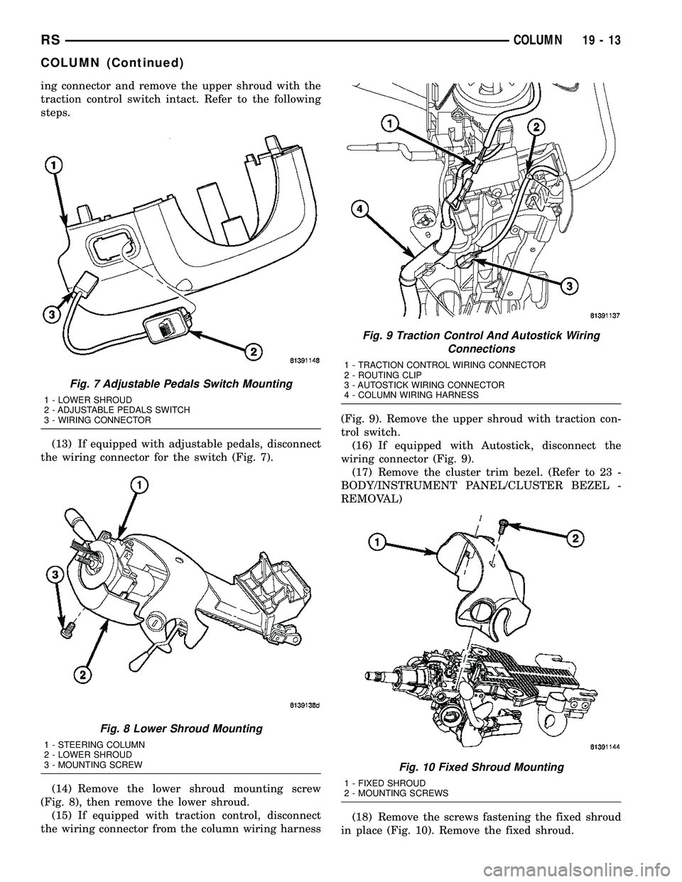
ing connector and remove the upper shroud with the
traction control switch intact. Refer to the following
steps.
(13) If equipped with adjustable pedals, disconnect
the wiring connector for the switch (Fig. 7).
(14) Remove the lower shroud mounting screw
(Fig. 8), then remove the lower shroud.
(15) If equipped with traction control, disconnect
the wiring connector from the column wiring harness(Fig. 9). Remove the upper shroud with traction con-
trol switch.
(16) If equipped with Autostick, disconnect the
wiring connector (Fig. 9).
(17) Remove the cluster trim bezel. (Refer to 23 -
BODY/INSTRUMENT PANEL/CLUSTER BEZEL -
REMOVAL)
(18) Remove the screws fastening the fixed shroud
in place (Fig. 10). Remove the fixed shroud.
Fig. 7 Adjustable Pedals Switch Mounting
1 - LOWER SHROUD
2 - ADJUSTABLE PEDALS SWITCH
3 - WIRING CONNECTOR
Fig. 8 Lower Shroud Mounting
1 - STEERING COLUMN
2 - LOWER SHROUD
3 - MOUNTING SCREW
Fig. 9 Traction Control And Autostick Wiring
Connections
1 - TRACTION CONTROL WIRING CONNECTOR
2 - ROUTING CLIP
3 - AUTOSTICK WIRING CONNECTOR
4 - COLUMN WIRING HARNESS
Fig. 10 Fixed Shroud Mounting
1 - FIXED SHROUD
2 - MOUNTING SCREWS
RSCOLUMN19-13
COLUMN (Continued)