Page 1655 of 2339
(60) Install low/reverse accumulator plug (Fig.
150).
(61) Install low/reverse accumulator snap ring
(Fig. 151).
NOTE: Depending on engine application, some
accumulators will have two springs, and others will
have one spring. The springs are color-coded for
application and year.(62) Install underdrive and overdrive accumulators
(Fig. 152).
(63) Install valve body to transaxle (Fig. 153).
Rotate manual valve shaft fully clockwise to ease
installation. Make sure park rod rollers are posi-
tioned within park guide bracket.
Fig. 150 Install Low/Reverse Accumulator Plug
(Cover)
1 - ADJUSTABLE PLIERS
2 - PLUG
Fig. 151 Install Low/Reverse Accumulator Snap
Ring
1 - SNAP RING
2 - PLUG
Fig. 152 Underdrive and Overdrive Accumulators
1 - OVERDRIVE PISTON AND SPRING
2 - UNDERDRIVE PISTON AND SPRING
Fig. 153 Install Valve Body
1 - VALVE BODY
21 - 194 41TE AUTOMATIC TRANSAXLERS
41TE AUTOMATIC TRANSAXLE (Continued)
Page 1656 of 2339
(64) Install and torque valve body-to-case bolts to
12 N´m (105 in. lbs.) (Fig. 154).
(65) Install oil filter and new o-ring (Fig. 155).(66) Apply an 1/8º bead of MopartATF RTV (MS-
GF41) to oil pan and immediately install to case (Fig.
156).
(67) Install oil pan-to-case bolts and torque to 19
N´m (165 in. lbs.).
(68) Install solenoid/pressure switch assembly and
gasket to case (Fig. 157).
Fig. 154 Install Valve Body-to-Case Bolts
1 - VALVE BODY ATTACHING BOLTS (18)
2 - VALVE BODY
Fig. 155 Install Oil Filter
1 - OIL FILTER
2 - O-RING
Fig. 156 Install Oil Pan
1 - OIL PAN
2 - 1/8 INCH BEAD OF MOPARTATF RTV (MS-GF41)
3 - OIL FILTER
Fig. 157 Solenoid/Pressure Switch Assembly and
Gasket
1 - SOLENOID/PRESSURE SWITCH ASSEMBLY
2 - GASKET
RS41TE AUTOMATIC TRANSAXLE21 - 195
41TE AUTOMATIC TRANSAXLE (Continued)
Page 1673 of 2339
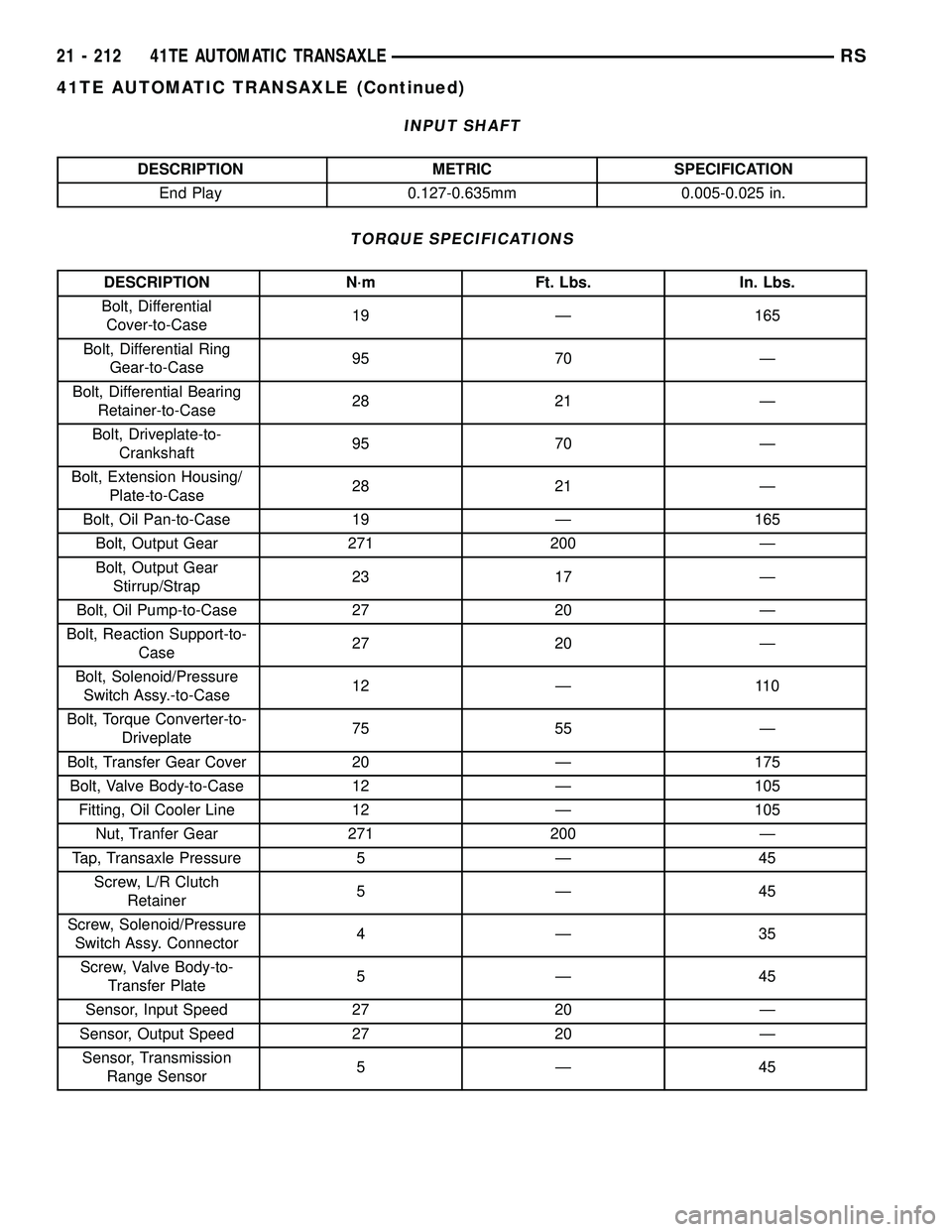
INPUT SHAFT
DESCRIPTION METRIC SPECIFICATION
End Play 0.127-0.635mm 0.005-0.025 in.
TORQUE SPECIFICATIONS
DESCRIPTION N´m Ft. Lbs. In. Lbs.
Bolt, Differential
Cover-to-Case19 Ð 165
Bolt, Differential Ring
Gear-to-Case95 70 Ð
Bolt, Differential Bearing
Retainer-to-Case28 21 Ð
Bolt, Driveplate-to-
Crankshaft95 70 Ð
Bolt, Extension Housing/
Plate-to-Case28 21 Ð
Bolt, Oil Pan-to-Case 19 Ð 165
Bolt, Output Gear 271 200 Ð
Bolt, Output Gear
Stirrup/Strap23 17 Ð
Bolt, Oil Pump-to-Case 27 20 Ð
Bolt, Reaction Support-to-
Case27 20 Ð
Bolt, Solenoid/Pressure
Switch Assy.-to-Case12 Ð 110
Bolt, Torque Converter-to-
Driveplate75 55 Ð
Bolt, Transfer Gear Cover 20 Ð 175
Bolt, Valve Body-to-Case 12 Ð 105
Fitting, Oil Cooler Line 12 Ð 105
Nut, Tranfer Gear 271 200 Ð
Tap, Transaxle Pressure 5 Ð 45
Screw, L/R Clutch
Retainer5Ð45
Screw, Solenoid/Pressure
Switch Assy. Connector4Ð35
Screw, Valve Body-to-
Transfer Plate5Ð45
Sensor, Input Speed 27 20 Ð
Sensor, Output Speed 27 20 Ð
Sensor, Transmission
Range Sensor5Ð45
21 - 212 41TE AUTOMATIC TRANSAXLERS
41TE AUTOMATIC TRANSAXLE (Continued)
Page 1679 of 2339
ACCUMULATOR
DESCRIPTION
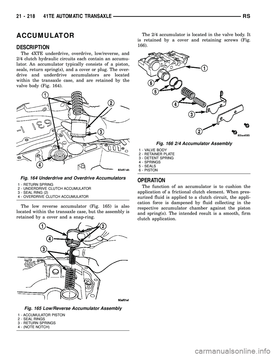
The 4XTE underdrive, overdrive, low/reverse, and
2/4 clutch hydraulic circuits each contain an accumu-
lator. An accumulator typically consists of a piston,
seals, return spring(s), and a cover or plug. The over-
drive and underdrive accumulators are located
within the transaxle case, and are retained by the
valve body (Fig. 164).
The low reverse accumulator (Fig. 165) is also
located within the transaxle case, but the assembly is
retained by a cover and a snap-ring.The 2/4 accumulator is located in the valve body. It
is retained by a cover and retaining screws (Fig.
166).
OPERATION
The function of an accumulator is to cushion the
application of a frictional clutch element. When pres-
surized fluid is applied to a clutch circuit, the appli-
cation force is dampened by fluid collecting in the
respective accumulator chamber against the piston
and spring(s). The intended result is a smooth, firm
clutch application.
Fig. 164 Underdrive and Overdrive Accumulators
1 - RETURN SPRING
2 - UNDERDRIVE CLUTCH ACCUMULATOR
3 - SEAL RING (2)
4 - OVERDRIVE CLUTCH ACCUMULATOR
Fig. 165 Low/Reverse Accumulator Assembly
1 - ACCUMULATOR PISTON
2 - SEAL RINGS
3 - RETURN SPRINGS
4 - (NOTE NOTCH)
Fig. 166 2/4 Accumulator Assembly
1 - VALVE BODY
2 - RETAINER PLATE
3 - DETENT SPRING
4 - SPRINGS
5 - SEALS
6 - PISTON
21 - 218 41TE AUTOMATIC TRANSAXLERS
Page 1693 of 2339
FLUID/FILTER SERVICE (RECOMMENDED)
(1) Raise vehicle on a hoist. Refer to LUBRICA-
TION and MAINTENANCE for proper procedures.
Place a drain container with a large opening, under
transaxle oil pan.
(2) Loosen pan bolts and tap the pan at one corner
to break it loose allowing fluid to drain, then remove
the oil pan.
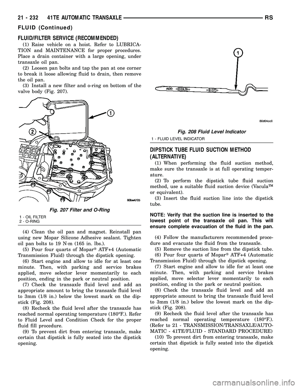
(3) Install a new filter and o-ring on bottom of the
valve body (Fig. 207).
(4) Clean the oil pan and magnet. Reinstall pan
using new Mopar Silicone Adhesive sealant. Tighten
oil pan bolts to 19 N´m (165 in. lbs.).
(5) Pour four quarts of MopartATF+4 (Automatic
Transmission Fluid) through the dipstick opening.
(6) Start engine and allow to idle for at least one
minute. Then, with parking and service brakes
applied, move selector lever momentarily to each
position, ending in the park or neutral position.
(7) Check the transaxle fluid level and add an
appropriate amount to bring the transaxle fluid level
to 3mm (1/8 in.) below the lowest mark on the dip-
stick (Fig. 208).
(8) Recheck the fluid level after the transaxle has
reached normal operating temperature (180ÉF.). Refer
to Fluid Level and Condition Check for the proper
fluid fill procedure.
(9) To prevent dirt from entering transaxle, make
certain that dipstick is fully seated into the dipstick
opening.
DIPSTICK TUBE FLUID SUCTION METHOD
(ALTERNATIVE)
(1) When performing the fluid suction method,
make sure the transaxle is at full operating temper-
ature.
(2) To perform the dipstick tube fluid suction
method, use a suitable fluid suction device (VaculaŸ
or equivalent).
(3) Insert the fluid suction line into the dipstick
tube.
NOTE: Verify that the suction line is inserted to the
lowest point of the transaxle oil pan. This will
ensure complete evacuation of the fluid in the pan.
(4) Follow the manufacturers recommended proce-
dure and evacuate the fluid from the transaxle.
(5) Remove the suction line from the dipstick tube.
(6) Pour four quarts of MopartATF+4 (Automatic
Transmission Fluid) through the dipstick opening.
(7) Start engine and allow to idle for at least one
minute. Then, with parking and service brakes
applied, move selector lever momentarily to each
position, ending in the park or neutral position.
(8) Check the transaxle fluid level and add an
appropriate amount to bring the transaxle fluid level
to 3mm (1/8 in.) below the lowest mark on the dip-
stick (Fig. 208).
(9) Recheck the fluid level after the transaxle has
reached normal operating temperature (180ÉF.).
(Refer to 21 - TRANSMISSION/TRANSAXLE/AUTO-
MATIC - 41TE/FLUID - STANDARD PROCEDURE)
(10) To prevent dirt from entering transaxle, make
certain that dipstick is fully seated into the dipstick
opening.
Fig. 207 Filter and O-Ring
1 - OIL FILTER
2 - O-RING
Fig. 208 Fluid Level Indicator
1 - FLUID LEVEL INDICATOR
21 - 232 41TE AUTOMATIC TRANSAXLERS
FLUID (Continued)
Page 1722 of 2339
OIL PUMP
DESCRIPTION
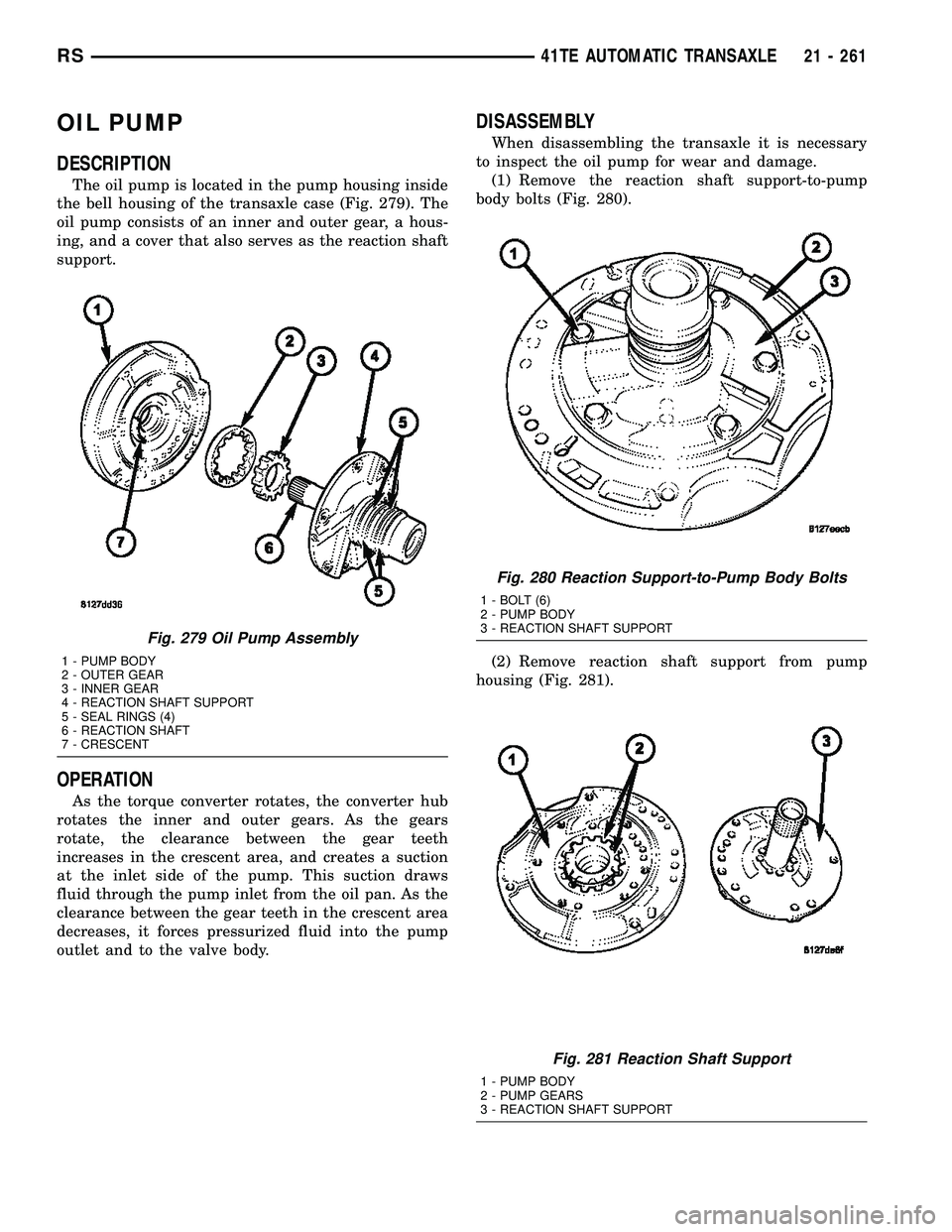
The oil pump is located in the pump housing inside
the bell housing of the transaxle case (Fig. 279). The
oil pump consists of an inner and outer gear, a hous-
ing, and a cover that also serves as the reaction shaft
support.
OPERATION
As the torque converter rotates, the converter hub
rotates the inner and outer gears. As the gears
rotate, the clearance between the gear teeth
increases in the crescent area, and creates a suction
at the inlet side of the pump. This suction draws
fluid through the pump inlet from the oil pan. As the
clearance between the gear teeth in the crescent area
decreases, it forces pressurized fluid into the pump
outlet and to the valve body.
DISASSEMBLY
When disassembling the transaxle it is necessary
to inspect the oil pump for wear and damage.
(1) Remove the reaction shaft support-to-pump
body bolts (Fig. 280).
(2) Remove reaction shaft support from pump
housing (Fig. 281).
Fig. 279 Oil Pump Assembly
1 - PUMP BODY
2 - OUTER GEAR
3 - INNER GEAR
4 - REACTION SHAFT SUPPORT
5 - SEAL RINGS (4)
6 - REACTION SHAFT
7 - CRESCENT
Fig. 280 Reaction Support-to-Pump Body Bolts
1 - BOLT (6)
2 - PUMP BODY
3 - REACTION SHAFT SUPPORT
Fig. 281 Reaction Shaft Support
1 - PUMP BODY
2 - PUMP GEARS
3 - REACTION SHAFT SUPPORT
RS41TE AUTOMATIC TRANSAXLE21 - 261
Page 1723 of 2339
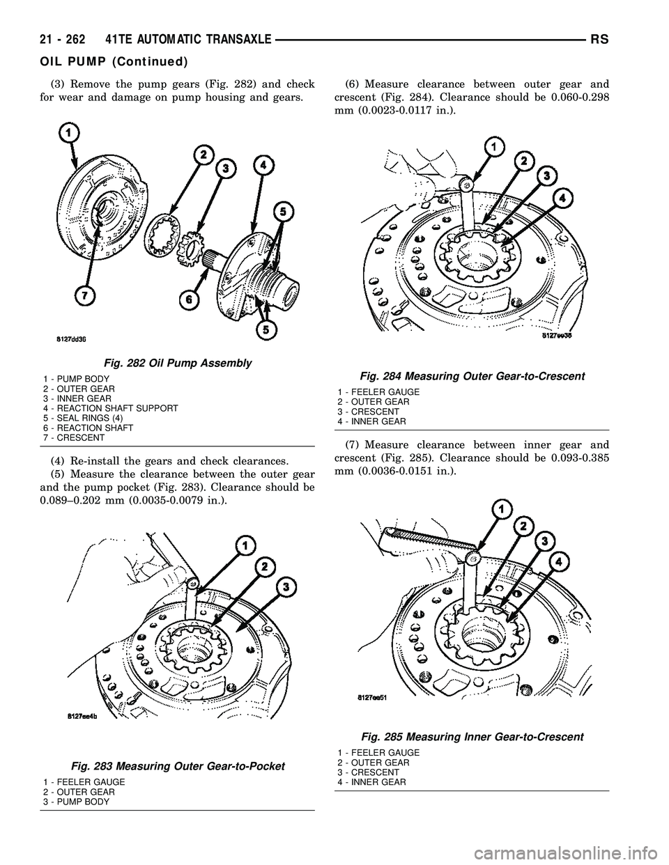
(3) Remove the pump gears (Fig. 282) and check
for wear and damage on pump housing and gears.
(4) Re-install the gears and check clearances.
(5) Measure the clearance between the outer gear
and the pump pocket (Fig. 283). Clearance should be
0.089±0.202 mm (0.0035-0.0079 in.).(6) Measure clearance between outer gear and
crescent (Fig. 284). Clearance should be 0.060-0.298
mm (0.0023-0.0117 in.).
(7) Measure clearance between inner gear and
crescent (Fig. 285). Clearance should be 0.093-0.385
mm (0.0036-0.0151 in.).
Fig. 282 Oil Pump Assembly
1 - PUMP BODY
2 - OUTER GEAR
3 - INNER GEAR
4 - REACTION SHAFT SUPPORT
5 - SEAL RINGS (4)
6 - REACTION SHAFT
7 - CRESCENT
Fig. 283 Measuring Outer Gear-to-Pocket
1 - FEELER GAUGE
2 - OUTER GEAR
3 - PUMP BODY
Fig. 284 Measuring Outer Gear-to-Crescent
1 - FEELER GAUGE
2 - OUTER GEAR
3 - CRESCENT
4 - INNER GEAR
Fig. 285 Measuring Inner Gear-to-Crescent
1 - FEELER GAUGE
2 - OUTER GEAR
3 - CRESCENT
4 - INNER GEAR
21 - 262 41TE AUTOMATIC TRANSAXLERS
OIL PUMP (Continued)
Page 1724 of 2339
(8) Position an appropriate piece of Plastigage
across both pump gears.
(9) Align the Plastigage to a flat area on the reac-
tion shaft support housing.
(10) Install the reaction shaft to the pump housing
(Fig. 280). Tighten the bolts to 27 N´m (20 ft. lbs.).
(11) Remove bolts and carefully separate the hous-
ings. Measure the Plastigage following the instruc-
tions supplied.
(12) Clearance between both gear end faces and
the reaction shaft support should be 0.020-0.046 mm
(0.0008-0.0018 in.).
ASSEMBLY
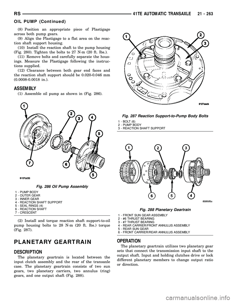
(1) Assemble oil pump as shown in (Fig. 286).
(2) Install and torque reaction shaft support-to-oil
pump housing bolts to 28 N´m (20 ft. lbs.) torque
(Fig. 287).
PLANETARY GEARTRAIN
DESCRIPTION
The planetary geartrain is located between the
input clutch assembly and the rear of the transaxle
case. The planetary geartrain consists of two sun
gears, two planetary carriers, two annulus (ring)
gears, and one output shaft (Fig. 288).
OPERATION
The planetary geartrain utilizes two planetary gear
sets that connect the transmission input shaft to the
output shaft. Input and holding clutches drive or lock
different planetary members to change output ratio
or direction.
Fig. 286 Oil Pump Assembly
1 - PUMP BODY
2 - OUTER GEAR
3 - INNER GEAR
4 - REACTION SHAFT SUPPORT
5 - SEAL RINGS (4)
6 - REACTION SHAFT
7 - CRESCENT
Fig. 287 Reaction Support-to-Pump Body Bolts
1 - BOLT (6)
2 - PUMP BODY
3 - REACTION SHAFT SUPPORT
Fig. 288 Planetary Geartrain
1 - FRONT SUN GEAR ASSEMBLY
2 - #6 THRUST BEARING
3 - #7 THRUST BEARING
4 - REAR CARRIER/FRONT ANNULUS ASSEMBLY
5 - REAR SUN GEAR
6 - FRONT CARRIER/REAR ANNULUS ASSEMBLY
RS41TE AUTOMATIC TRANSAXLE21 - 263
OIL PUMP (Continued)