2005 CHRYSLER CARAVAN body
[x] Cancel search: bodyPage 1398 of 2339
IDLE AIR CONTROL MOTOR
DESCRIPTION
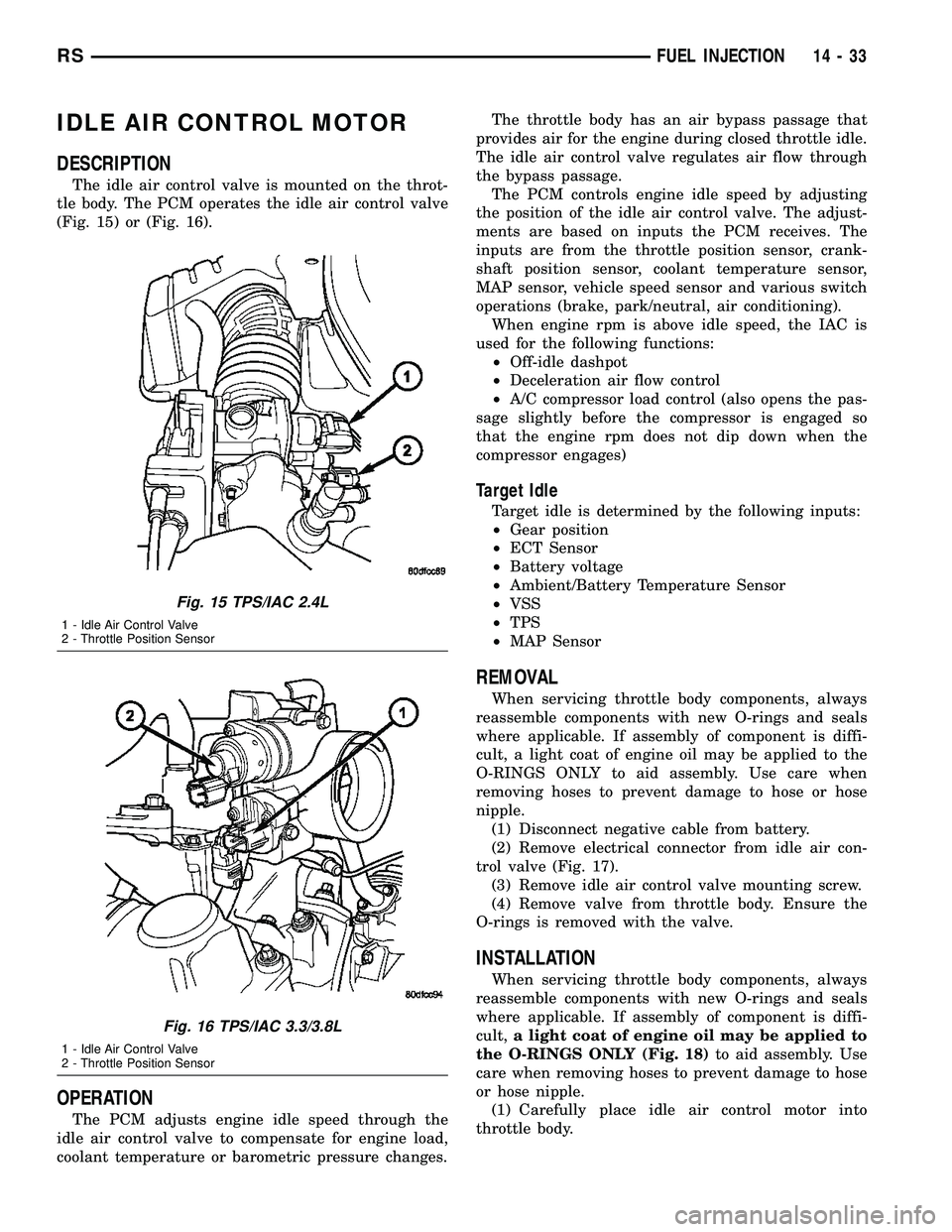
The idle air control valve is mounted on the throt-
tle body. The PCM operates the idle air control valve
(Fig. 15) or (Fig. 16).
OPERATION
The PCM adjusts engine idle speed through the
idle air control valve to compensate for engine load,
coolant temperature or barometric pressure changes.The throttle body has an air bypass passage that
provides air for the engine during closed throttle idle.
The idle air control valve regulates air flow through
the bypass passage.
The PCM controls engine idle speed by adjusting
the position of the idle air control valve. The adjust-
ments are based on inputs the PCM receives. The
inputs are from the throttle position sensor, crank-
shaft position sensor, coolant temperature sensor,
MAP sensor, vehicle speed sensor and various switch
operations (brake, park/neutral, air conditioning).
When engine rpm is above idle speed, the IAC is
used for the following functions:
²Off-idle dashpot
²Deceleration air flow control
²A/C compressor load control (also opens the pas-
sage slightly before the compressor is engaged so
that the engine rpm does not dip down when the
compressor engages)
Target Idle
Target idle is determined by the following inputs:
²Gear position
²ECT Sensor
²Battery voltage
²Ambient/Battery Temperature Sensor
²VSS
²TPS
²MAP Sensor
REMOVAL
When servicing throttle body components, always
reassemble components with new O-rings and seals
where applicable. If assembly of component is diffi-
cult, a light coat of engine oil may be applied to the
O-RINGS ONLY to aid assembly. Use care when
removing hoses to prevent damage to hose or hose
nipple.
(1) Disconnect negative cable from battery.
(2) Remove electrical connector from idle air con-
trol valve (Fig. 17).
(3) Remove idle air control valve mounting screw.
(4) Remove valve from throttle body. Ensure the
O-rings is removed with the valve.
INSTALLATION
When servicing throttle body components, always
reassemble components with new O-rings and seals
where applicable. If assembly of component is diffi-
cult,a light coat of engine oil may be applied to
the O-RINGS ONLY (Fig. 18)to aid assembly. Use
care when removing hoses to prevent damage to hose
or hose nipple.
(1) Carefully place idle air control motor into
throttle body.
Fig. 15 TPS/IAC 2.4L
1 - Idle Air Control Valve
2 - Throttle Position Sensor
Fig. 16 TPS/IAC 3.3/3.8L
1 - Idle Air Control Valve
2 - Throttle Position Sensor
RSFUEL INJECTION14-33
Page 1404 of 2339
(2) Install sensor and tighten to 27 N´m (20 ft.
lbs.) (Fig. 23).
(3) Connect the electrical connector for the O2 sen-
sor and install onto bracket.
(4) Lower vehicle.
(5) Connect the negative battery cable.
INSTALLATION - UPSTREAM 1/1 - 3.3/3.8L
The engines uses two heated oxygen sensors.
(1) After removing the sensor, the exhaust mani-
fold threads must be cleaned with an 18 mm X 1.5 +
6E tap. If reusing the original sensor, coat the sensor
threads with an anti-seize compound such as Loctite
771- 64 or equivalent. New sensors have compound
on the threads and do not require an additional coat-
ing.
(2) Install sensor and tighten to 27 N´m (20 ft.
lbs.).
(3) Connect the electrical connector for the O2 sen-
sor and install onto bracket.
(4) Connect the electrical connector for the speed
control servo.
(5) Install the speed control servo and bracket
refer to the Speed Control Servo for more informa-
tion.
(6) Connect the speed control vacuum harness to
servo.
(7) Install the battery tray, refer to the Battery
section for more information.
(8) Install battery, refer to the Battery section for
more information.
INSTALLATION DOWNSTREAM 2/1 -
2.4/3.3/3.8L
The O2S is located on the side of the catalytic con-
verter.
Threads of new oxygen sensors are factory coated
with anti-seize compound to aid in removal.DO
NOT add any additional anti-seize compound to
the threads of a new oxygen sensor.
(1) Install sensor and tighten to 27 N´m (20 ft.
lbs.).
(2) Connect the electrical connector.
(3) Lower vehicle.
(4) Install the negative battery cable.
THROTTLE BODY
DESCRIPTION
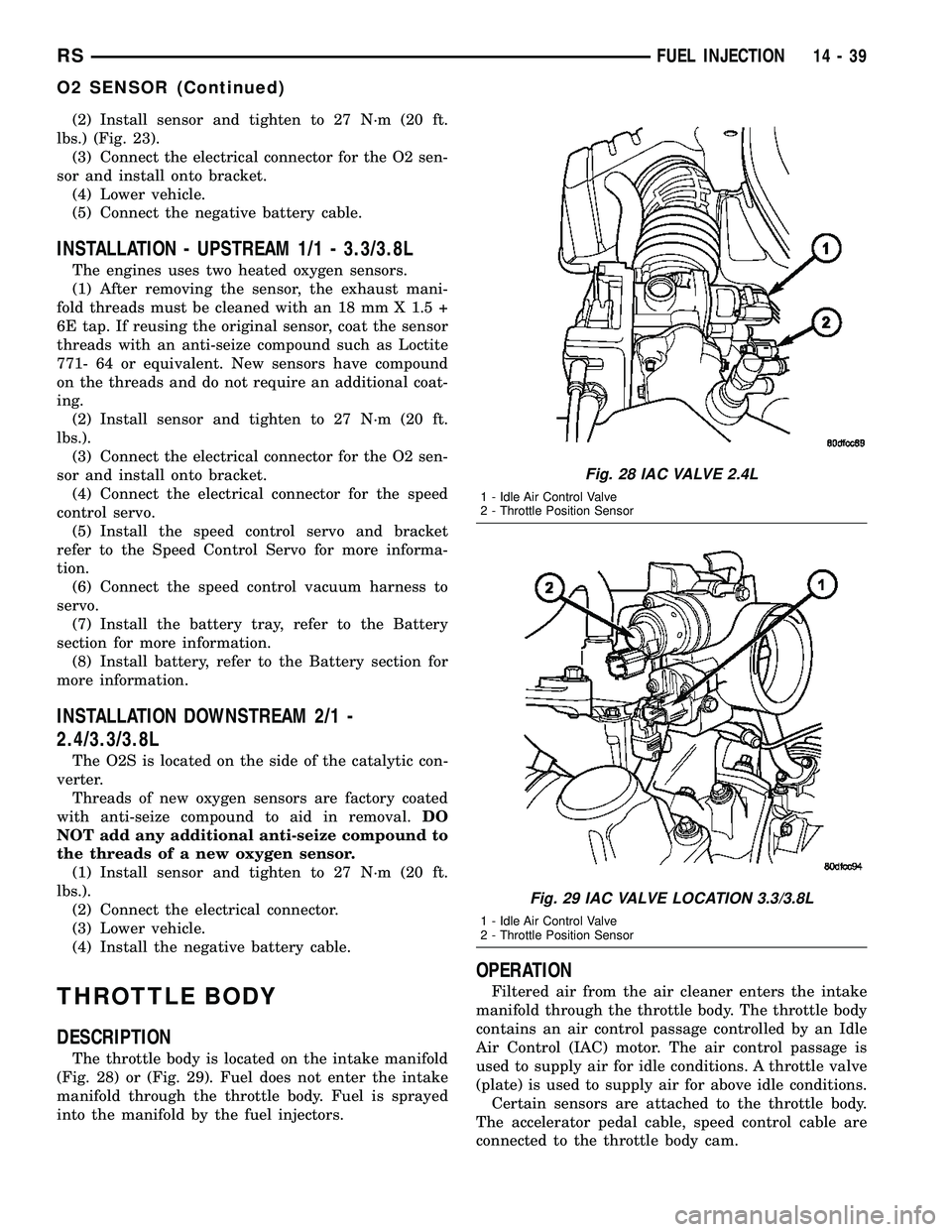
The throttle body is located on the intake manifold
(Fig. 28) or (Fig. 29). Fuel does not enter the intake
manifold through the throttle body. Fuel is sprayed
into the manifold by the fuel injectors.
OPERATION
Filtered air from the air cleaner enters the intake
manifold through the throttle body. The throttle body
contains an air control passage controlled by an Idle
Air Control (IAC) motor. The air control passage is
used to supply air for idle conditions. A throttle valve
(plate) is used to supply air for above idle conditions.
Certain sensors are attached to the throttle body.
The accelerator pedal cable, speed control cable are
connected to the throttle body cam.
Fig. 28 IAC VALVE 2.4L
1 - Idle Air Control Valve
2 - Throttle Position Sensor
Fig. 29 IAC VALVE LOCATION 3.3/3.8L
1 - Idle Air Control Valve
2 - Throttle Position Sensor
RSFUEL INJECTION14-39
O2 SENSOR (Continued)
Page 1405 of 2339
A (factory adjusted) set screw is used to mechani-
cally limit the position of the throttle body throttle
plate.Never attempt to adjust the engine idle
speed using this screw.All idle speed functions are
controlled by the PCM.
REMOVAL
(1) Disconnect negative cable from battery cable.
(2) Remove air inlet to throttle body hose clamp.
(3) Remove throttle and the speed control (if
equipped) cables from lever and bracket.
(4) Disconnect electrical connectors from the idle
air control motor and throttle position sensor (TPS)
(Fig. 28) or (Fig. 29).
(5) Remove throttle body to intake manifold
attaching bolts.
(6) Remove throttle body and gasket.
INSTALLATION
(1) Install a new gasket, if required.
(2) Install throttle body.
(3) Tighten throttle body mounting bolts. The 2.4L
to 28.2 N´m (250 50 in. lbs.) torque, The 3.3/3.8L to
11.6 N´m (105 20 in. lbs.) torque.
(4) Connect electrical connectors to the idle air
control motor and throttle position sensor (TPS) (Fig.
28) or (Fig. 29).
(5) Install air inlet to throttle body hose clamp and
tighten.
(6) Connect negative cable to battery cable.
THROTTLE CONTROL CABLE
REMOVAL
(1) Working from the engine compartment, hold
the throttle body throttle lever in the wide open posi-
tion.
(2) Remove the throttle cable from the throttle
body cam.
(3) From inside the vehicle, hold up the pedal and
remove the cable retainer and throttle cable from the
upper end of the pedal shaft.
(4) Remove retainer clip from throttle cable and
grommet at dash panel.
(5) From the engine compartment, pull the throttle
cable and gromment out of the dash panel.
(6) Remove the throttle cable from throttle bracket
by carefully compressing both retaining ears simulta-
neously then gently pull the throttle cable from
throttle bracket or if it is the slide snap design you
have to slide the locking tab out of the hole and then
slide the cable assembly out of the bracket.
INSTALLATION
(1) From the engine compartment, push the hous-
ing end fitting and grommet into the dash panel.In-
stall gromment into the dash panel.
(2) Install the cable housing (throttle body end)
into the cable mounting bracket on the engine.
(3) From inside the vehicle, hold up the pedal and
install throttle cable and cable retainer in the upper
end of the pedal shaft.
(4) At the dash panel, install the cable retainer
clip between the end of the throttle cable fitting and
grommet
(5) From the engine compartment, rotate the
throttle lever wide open and install the throttle
cable.
THROTTLE POSITION SENSOR
DESCRIPTION
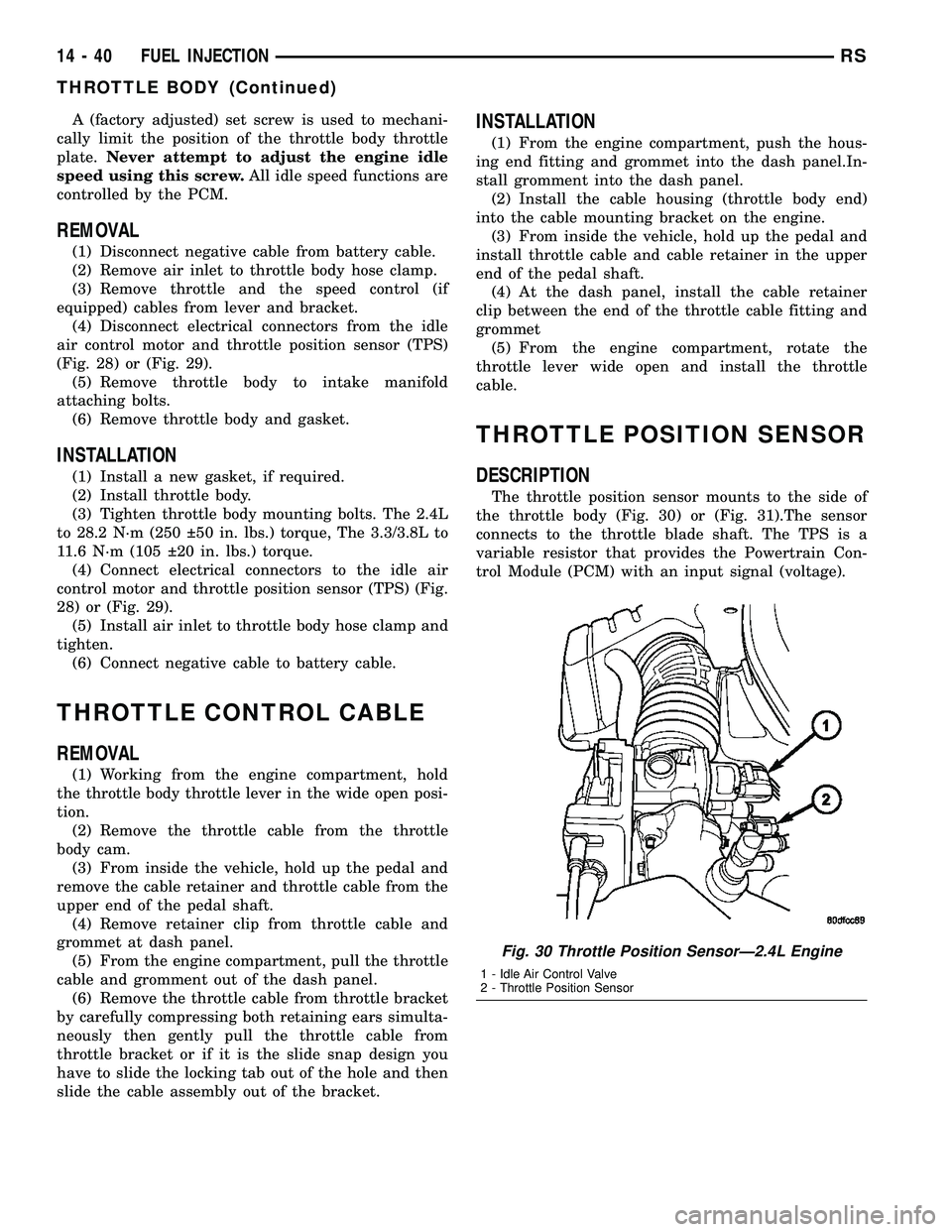
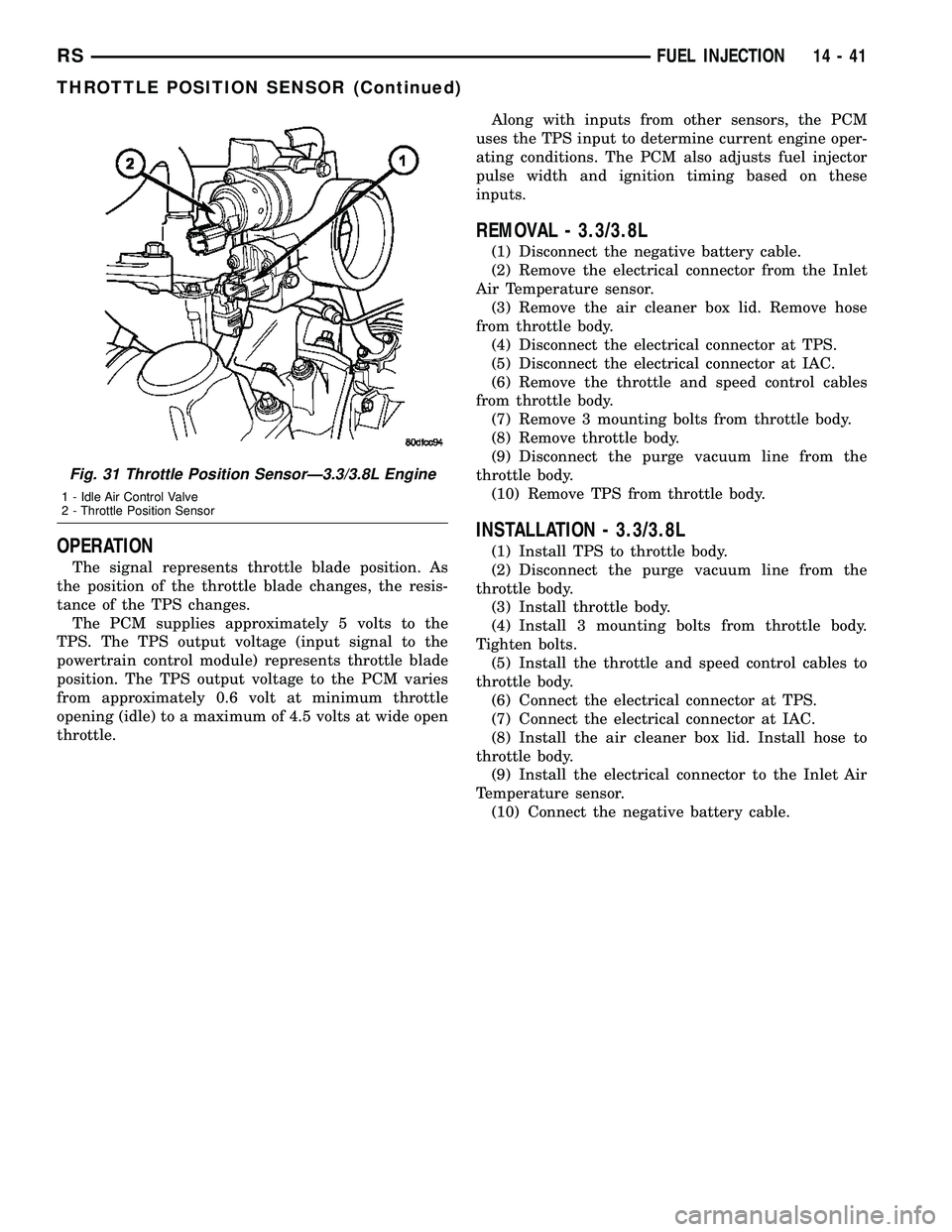
The throttle position sensor mounts to the side of
the throttle body (Fig. 30) or (Fig. 31).The sensor
connects to the throttle blade shaft. The TPS is a
variable resistor that provides the Powertrain Con-
trol Module (PCM) with an input signal (voltage).
Fig. 30 Throttle Position SensorÐ2.4L Engine
1 - Idle Air Control Valve
2 - Throttle Position Sensor
14 - 40 FUEL INJECTIONRS
THROTTLE BODY (Continued)
Page 1406 of 2339
OPERATION
The signal represents throttle blade position. As
the position of the throttle blade changes, the resis-
tance of the TPS changes.
The PCM supplies approximately 5 volts to the
TPS. The TPS output voltage (input signal to the
powertrain control module) represents throttle blade
position. The TPS output voltage to the PCM varies
from approximately 0.6 volt at minimum throttle
opening (idle) to a maximum of 4.5 volts at wide open
throttle.Along with inputs from other sensors, the PCM
uses the TPS input to determine current engine oper-
ating conditions. The PCM also adjusts fuel injector
pulse width and ignition timing based on these
inputs.
REMOVAL - 3.3/3.8L
(1) Disconnect the negative battery cable.
(2) Remove the electrical connector from the Inlet
Air Temperature sensor.
(3) Remove the air cleaner box lid. Remove hose
from throttle body.
(4) Disconnect the electrical connector at TPS.
(5) Disconnect the electrical connector at IAC.
(6) Remove the throttle and speed control cables
from throttle body.
(7) Remove 3 mounting bolts from throttle body.
(8) Remove throttle body.
(9) Disconnect the purge vacuum line from the
throttle body.
(10) Remove TPS from throttle body.
INSTALLATION - 3.3/3.8L
(1) Install TPS to throttle body.
(2) Disconnect the purge vacuum line from the
throttle body.
(3) Install throttle body.
(4) Install 3 mounting bolts from throttle body.
Tighten bolts.
(5) Install the throttle and speed control cables to
throttle body.
(6) Connect the electrical connector at TPS.
(7) Connect the electrical connector at IAC.
(8) Install the air cleaner box lid. Install hose to
throttle body.
(9) Install the electrical connector to the Inlet Air
Temperature sensor.
(10) Connect the negative battery cable.
Fig. 31 Throttle Position SensorÐ3.3/3.8L Engine
1 - Idle Air Control Valve
2 - Throttle Position Sensor
RSFUEL INJECTION14-41
THROTTLE POSITION SENSOR (Continued)
Page 1411 of 2339
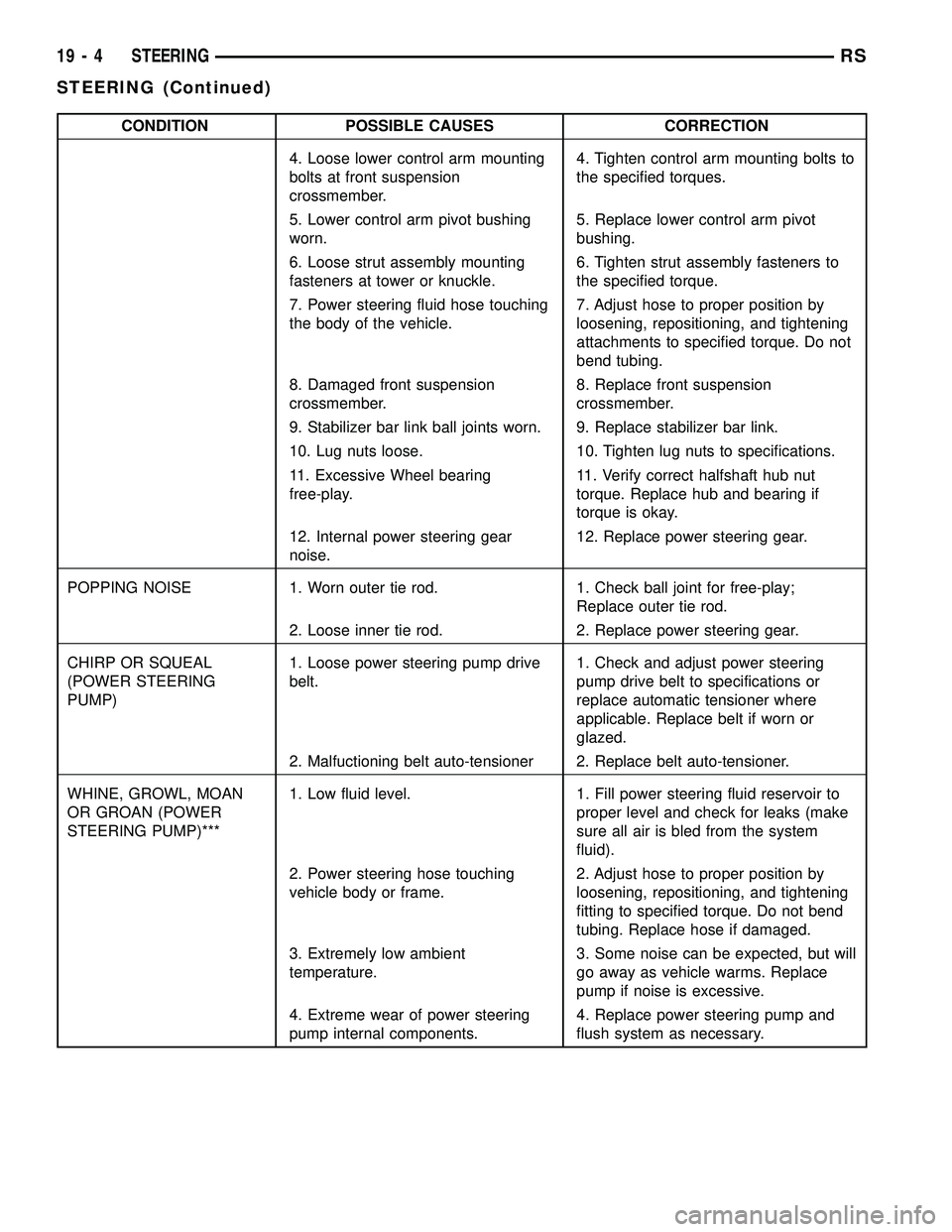
CONDITION POSSIBLE CAUSES CORRECTION
4. Loose lower control arm mounting
bolts at front suspension
crossmember.4. Tighten control arm mounting bolts to
the specified torques.
5. Lower control arm pivot bushing
worn.5. Replace lower control arm pivot
bushing.
6. Loose strut assembly mounting
fasteners at tower or knuckle.6. Tighten strut assembly fasteners to
the specified torque.
7. Power steering fluid hose touching
the body of the vehicle.7. Adjust hose to proper position by
loosening, repositioning, and tightening
attachments to specified torque. Do not
bend tubing.
8. Damaged front suspension
crossmember.8. Replace front suspension
crossmember.
9. Stabilizer bar link ball joints worn. 9. Replace stabilizer bar link.
10. Lug nuts loose. 10. Tighten lug nuts to specifications.
11. Excessive Wheel bearing
free-play.11. Verify correct halfshaft hub nut
torque. Replace hub and bearing if
torque is okay.
12. Internal power steering gear
noise.12. Replace power steering gear.
POPPING NOISE 1. Worn outer tie rod. 1. Check ball joint for free-play;
Replace outer tie rod.
2. Loose inner tie rod. 2. Replace power steering gear.
CHIRP OR SQUEAL
(POWER STEERING
PUMP)1. Loose power steering pump drive
belt.1. Check and adjust power steering
pump drive belt to specifications or
replace automatic tensioner where
applicable. Replace belt if worn or
glazed.
2. Malfuctioning belt auto-tensioner 2. Replace belt auto-tensioner.
WHINE, GROWL, MOAN
OR GROAN (POWER
STEERING PUMP)***1. Low fluid level. 1. Fill power steering fluid reservoir to
proper level and check for leaks (make
sure all air is bled from the system
fluid).
2. Power steering hose touching
vehicle body or frame.2. Adjust hose to proper position by
loosening, repositioning, and tightening
fitting to specified torque. Do not bend
tubing. Replace hose if damaged.
3. Extremely low ambient
temperature.3. Some noise can be expected, but will
go away as vehicle warms. Replace
pump if noise is excessive.
4. Extreme wear of power steering
pump internal components.4. Replace power steering pump and
flush system as necessary.
19 - 4 STEERINGRS
STEERING (Continued)
Page 1419 of 2339
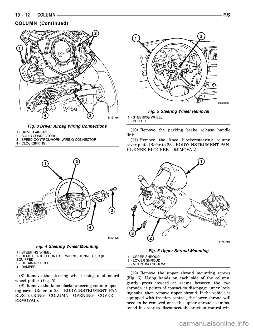
(8) Remove the steering wheel using a standard
wheel puller (Fig. 5).
(9) Remove the knee blocker/steering column open-
ing cover (Refer to 23 - BODY/INSTRUMENT PAN-
EL/STEERING COLUMN OPENING COVER -
REMOVAL).(10) Remove the parking brake release handle
link.
(11) Remove the knee blocker/steering column
cover plate (Refer to 23 - BODY/INSTRUMENT PAN-
EL/KNEE BLOCKER - REMOVAL).
(12) Remove the upper shroud mounting screws
(Fig. 6). Using hands on each side of the column,
gently press inward at seams between the two
shrouds at points of contact to disengage inner lock-
ing tabs, then remove upper shroud. If the vehicle is
equipped with traction control, the lower shroud will
need to be removed once the upper shroud is unfas-
tened in order to disconnect the traction control wir-
Fig. 3 Driver Airbag Wiring Connections
1 - DRIVER AIRBAG
2 - SQUIB CONNECTORS
3 - SPEED CONTROL/HORN WIRING CONNECTOR
4 - CLOCKSPRING
Fig. 4 Steering Wheel Mounting
1 - STEERING WHEEL
2 - REMOTE AUDIO CONTROL WIRING CONNECTOR (IF
EQUIPPED)
3 - RETAINING BOLT
4 - DAMPER
Fig. 5 Steering Wheel Removal
1 - STEERING WHEEL
2 - PULLER
Fig. 6 Upper Shroud Mounting
1 - UPPER SHROUD
2 - LOWER SHROUD
3 - MOUNTING SCREWS
19 - 12 COLUMNRS
COLUMN (Continued)
Page 1420 of 2339
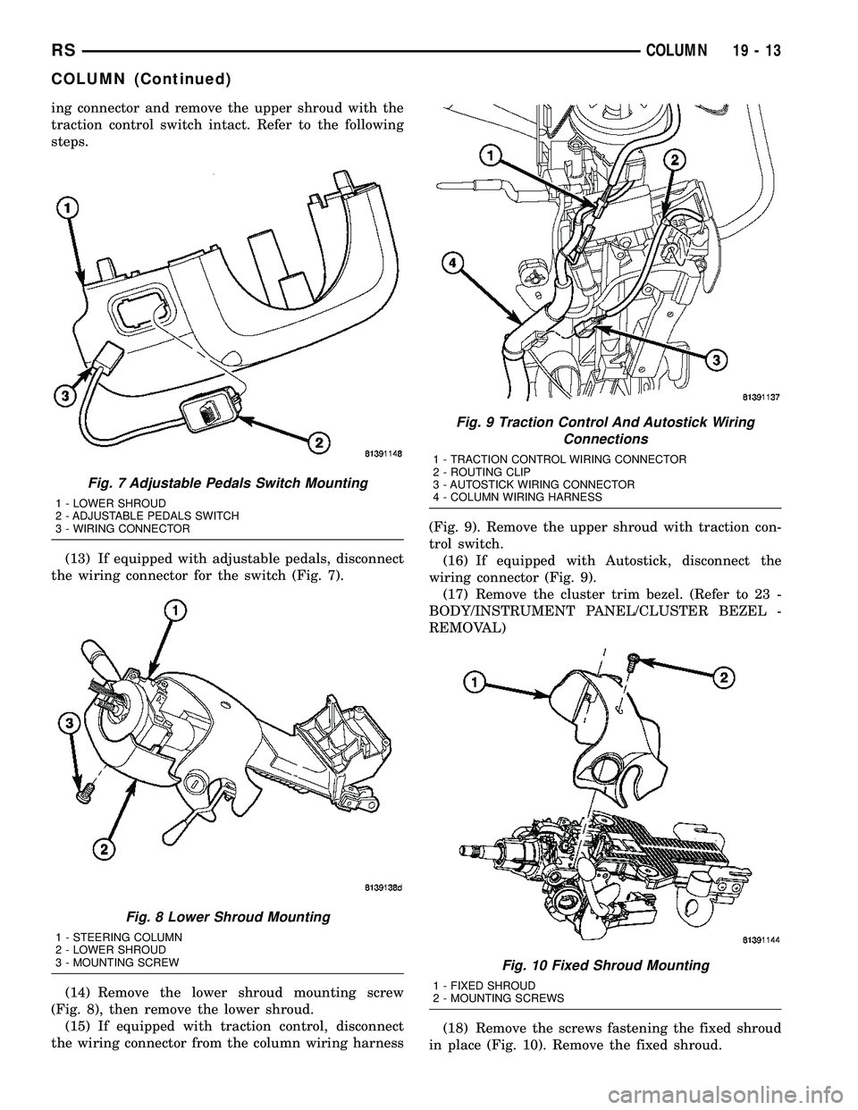
ing connector and remove the upper shroud with the
traction control switch intact. Refer to the following
steps.
(13) If equipped with adjustable pedals, disconnect
the wiring connector for the switch (Fig. 7).
(14) Remove the lower shroud mounting screw
(Fig. 8), then remove the lower shroud.
(15) If equipped with traction control, disconnect
the wiring connector from the column wiring harness(Fig. 9). Remove the upper shroud with traction con-
trol switch.
(16) If equipped with Autostick, disconnect the
wiring connector (Fig. 9).
(17) Remove the cluster trim bezel. (Refer to 23 -
BODY/INSTRUMENT PANEL/CLUSTER BEZEL -
REMOVAL)
(18) Remove the screws fastening the fixed shroud
in place (Fig. 10). Remove the fixed shroud.
Fig. 7 Adjustable Pedals Switch Mounting
1 - LOWER SHROUD
2 - ADJUSTABLE PEDALS SWITCH
3 - WIRING CONNECTOR
Fig. 8 Lower Shroud Mounting
1 - STEERING COLUMN
2 - LOWER SHROUD
3 - MOUNTING SCREW
Fig. 9 Traction Control And Autostick Wiring
Connections
1 - TRACTION CONTROL WIRING CONNECTOR
2 - ROUTING CLIP
3 - AUTOSTICK WIRING CONNECTOR
4 - COLUMN WIRING HARNESS
Fig. 10 Fixed Shroud Mounting
1 - FIXED SHROUD
2 - MOUNTING SCREWS
RSCOLUMN19-13
COLUMN (Continued)
Page 1424 of 2339

(19) Position the lower shroud on the column (Fig.
8). Install the lower shroud mounting screw. Tighten
the screw to 2 N´m (17 in. lbs.) torque.
(20) If equipped with adjustable pedals, Connect
the wiring connector for the switch (Fig. 7) to the col-
umn wiring harness.
(21) Position the upper shroud on top of the lower
shroud and snap it into place. Install the upper
shroud mounting screws (Fig. 6). Tighten the screws
to 2 N´m (17 in. lbs.) torque.
(22) Inspect shroud mating surfaces for excessive
gaps and correct as necessary.
(23) Install the cluster trim bezel (Refer to 23 -
BODY/INSTRUMENT PANEL/CLUSTER BEZEL -
INSTALLATION).
(24) Install the knee blocker/steering column cover
plate. (Refer to 23 - BODY/INSTRUMENT PANEL/
KNEE BLOCKER - INSTALLATION)
(25) Install the parking brake handle link.
(26) Install the knee blocker/steering column open-
ing cover. (Refer to 23 - BODY/INSTRUMENT PAN-
EL/STEERING COLUMN OPENING COVER -
INSTALLATION)
(27) Align the splines and install the steering
wheel on the steering column shaft(Refer to 19 -
STEERING/COLUMN/STEERING WHEEL -
INSTALLATION).
(28) Install the damper over the steering column
shaft (Fig. 4).
(29) Install the steering wheel retaining bolt (Fig.
4). Tighten the bolt to 61 N´m (45 ft. lbs.) torque.
(30) If the steering wheel is equipped with remote
audio controls, connect the wiring connector to the
clockspring (Fig. 4).
(31) Connect the two squib connectors to the
driver airbag (Fig. 3). The connectors are color coded
to avoid connector mix-up.
(32) Connect the speed control and horn connector
to the clockspring (Fig. 3).
(33) Install the airbag to the steering wheel.
Install the driver airbag mounting screws (Fig. 2).
Tighten screws to 10 N´m (90 in. lbs.) torque.
(34) Connect the battery negative (ground) cable to
battery post following special Diagnosis And Testing
procedure. (Refer to 8 - ELECTRICAL/RESTRAINTS
- DIAGNOSIS AND TESTING)
(35) Check operation of all steering column
mounted components.
(36) Road test vehicle to ensure proper operation
of steering.SPECIFICATIONS
COLUMN FASTENER TORQUE
DESCRIPTION N´mFt.
Lbs.In.
Lbs.
Driver Airbag Mounting Screws 10 Ð 90
Multi-Function Switch Mounting
Housing Set-Screw14 Ð 124
Shroud Attaching Screws - Fixed 3 Ð 23
Shroud Attaching Screws -
Lower/Upper2Ð17
SKIM Attaching Screw 4 Ð 30
Steering Column Coupling Pinch
Bolt28 Ð 250
Steering Column Mounting Nuts 12 Ð 105
Steering Wheel Retaining Bolt 61 45 Ð
IGNITION SWITCH
REMOVAL
The ignition switch attaches to the lock cylinder
housing on the end opposite the lock cylinder (Fig.
20). For ignition switch terminal and circuit identifi-
cation, refer to the appropriate wiring information.
The wiring information includes wiring diagrams,
proper wire and connector repair procedures, further
details on wire harness routing and retention, as well
as pin-out and location views for the various wire
harness connectors, splices and grounds.
(1) Disconnect negative cable from battery.
Fig. 20 Ignition SwitchÐViewed From Below
Column
1 - IGNITION SWITCH
2 - LOCK CYLINDER HOUSING
3 - RETAINING TABS
RSCOLUMN19-17
COLUMN (Continued)