Page 1916 of 2339
SEAT RECLINER/FORWARD
FOLDING MECHANISM
-SECOND ROW -FOLD-IN-
FLOOR
REMOVAL
(1) Remove seat back cover and foam (Fig. 66).
(Refer to 23 - BODY/SEATS/SEAT BACK COVER/
FOAM - REMOVAL)
(2) Remove two seat back frame bolts on each side
and remove frame (Fig. 67).(3) Remove the two reclining mechanism bolts
from each side of the frame (Fig. 68) and (Fig. 69).
(4) Remove both armrest rotating assembly. (Refer
to 23 - BODY/SEATS/ARMREST ROTATING
ASSEMBLY - REMOVAL).
INSTALLATION
(1) Install both armrest rotating assembly. (Refer
to 23 - BODY/SEATS/ARMREST ROTATING
ASSEMBLY - INSTALLATION).
(2) Install the two reclining mechanism bolts on
each side of frame (Fig. 68) and (Fig. 69).
(3) Install seat back frame (Fig. 67).
(4) Install seat back cover and foam (Fig. 66).
Fig. 66 SECOND ROW SEAT BACK
Fig. 67 SEAT BACK FRAME
1 - ATTACHING BOLTS
Fig. 68 SECOND ROW INBOARD SIDE
1 - ATTACHING BOLT
Fig. 69 SEAT BACK OUTBOARD SIDE
ATTACHING BOLTS
RSSEATS23 - 137
Page 1917 of 2339
SEAT CUSHION SIDE SHIELD -
SECOND ROW - FOLD-IN-
FLOOR
REMOVAL
(1) On outboard side remove forward folding han-
dle.
(2) Remove cup holder attaching screws (Fig. 70).
(3) Remove move rear attaching screw.
(4) Remove upper side shield.
INSTALLATION
(1) Place seat cushion upper side shield into posi-
tion.
(2) Place cup holder into position and install cup
holder attaching screws (Fig. 70).
(3) Install rear attaching screw.
(4) Outboard side install forward folding handle.
SEAT GAS STRUT - SECOND
ROW - FOLD-IN-FLOOR
REMOVAL
(1) Place second row seat in the upright position.
(2) Remove lower front shield (Fig. 71).
(3) Remove attaching pin (Fig. 72).
(4) Remove upper attaching screw (Fig. 73).
(5) Remove gas strut.
Fig. 70 SECOND ROW SEAT UPPER SIDE SHIELD
1 - REAR ATTACHING SCREW
2 - FORWARD FOLDING HANDLE
3 - CUP HOLDER ATTACHING SCREWS
Fig. 71 SECOND ROW LOWER FRONT SHIELD
1 - TRIM TOOL
Fig. 72 PROP RODS
1 - ATTACHING PIN
2 - ATTACHING SCREW
23 - 138 SEATSRS
Page 1918 of 2339
INSTALLATION
(1) Place gas strut into position.
(2) Install upper attaching screw (Fig. 73).
(3) Install attaching pin (Fig. 72).
(4) Install lower front shield (Fig. 74).
SEAT PROP ROD - SECOND
ROW - FOLD-IN-FLOOR
REMOVAL
(1) Place second row seat in the upright position.
(2) Remove lower front shield (Fig. 75) and (Fig.
76).
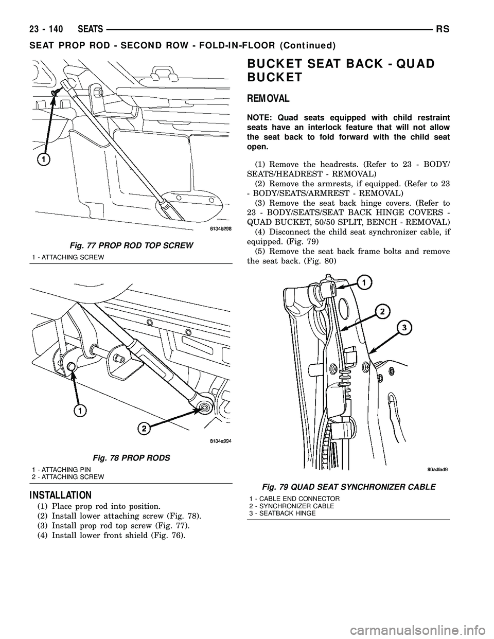
(3) Remove prop rod top screw (Fig. 77).
(4) Remove lower attaching screw (Fig. 78).
(5) Remove prop rod.
Fig. 73 GAS STRUT TOP SCREW
1 - ATTACHING SCREW
Fig. 74 SECOND ROW SEAT PROP ROD
1 - PROP ROD
Fig. 75 SECOND ROW LOWER FRONT SHIELD
1 - TRIM TOOL
Fig. 76 SECOND ROW SEAT PROP ROD
1 - PROP ROD
RSSEATS23 - 139
SEAT GAS STRUT - SECOND ROW - FOLD-IN-FLOOR (Continued)
Page 1919 of 2339

INSTALLATION
(1) Place prop rod into position.
(2) Install lower attaching screw (Fig. 78).
(3) Install prop rod top screw (Fig. 77).
(4) Install lower front shield (Fig. 76).
BUCKET SEAT BACK - QUAD
BUCKET
REMOVAL
NOTE: Quad seats equipped with child restraint
seats have an interlock feature that will not allow
the seat back to fold forward with the child seat
open.
(1) Remove the headrests. (Refer to 23 - BODY/
SEATS/HEADREST - REMOVAL)
(2) Remove the armrests, if equipped. (Refer to 23
- BODY/SEATS/ARMREST - REMOVAL)
(3) Remove the seat back hinge covers. (Refer to
23 - BODY/SEATS/SEAT BACK HINGE COVERS -
QUAD BUCKET, 50/50 SPLIT, BENCH - REMOVAL)
(4) Disconnect the child seat synchronizer cable, if
equipped. (Fig. 79)
(5) Remove the seat back frame bolts and remove
the seat back. (Fig. 80)
Fig. 77 PROP ROD TOP SCREW
1 - ATTACHING SCREW
Fig. 78 PROP RODS
1 - ATTACHING PIN
2 - ATTACHING SCREW
Fig. 79 QUAD SEAT SYNCHRONIZER CABLE
1 - CABLE END CONNECTOR
2 - SYNCHRONIZER CABLE
3 - SEATBACK HINGE
23 - 140 SEATSRS
SEAT PROP ROD - SECOND ROW - FOLD-IN-FLOOR (Continued)
Page 1925 of 2339

SEAT BACK HINGE COVERS -
QUAD BUCKET, 50/50 SPLIT,
BENCH
REMOVAL
(1) Remove seat from vehicle. Refer to Owner's
Manual for proper procedures.
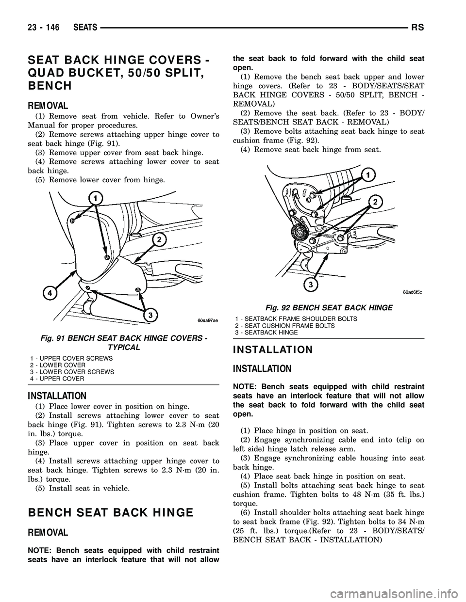
(2) Remove screws attaching upper hinge cover to
seat back hinge (Fig. 91).
(3) Remove upper cover from seat back hinge.
(4) Remove screws attaching lower cover to seat
back hinge.
(5) Remove lower cover from hinge.
INSTALLATION
(1) Place lower cover in position on hinge.
(2) Install screws attaching lower cover to seat
back hinge (Fig. 91). Tighten screws to 2.3 N´m (20
in. lbs.) torque.
(3) Place upper cover in position on seat back
hinge.
(4) Install screws attaching upper hinge cover to
seat back hinge. Tighten screws to 2.3 N´m (20 in.
lbs.) torque.
(5) Install seat in vehicle.
BENCH SEAT BACK HINGE
REMOVAL
NOTE: Bench seats equipped with child restraint
seats have an interlock feature that will not allowthe seat back to fold forward with the child seat
open.
(1) Remove the bench seat back upper and lower
hinge covers. (Refer to 23 - BODY/SEATS/SEAT
BACK HINGE COVERS - 50/50 SPLIT, BENCH -
REMOVAL)
(2) Remove the seat back. (Refer to 23 - BODY/
SEATS/BENCH SEAT BACK - REMOVAL)
(3) Remove bolts attaching seat back hinge to seat
cushion frame (Fig. 92).
(4) Remove seat back hinge from seat.
INSTALLATION
INSTALLATION
NOTE: Bench seats equipped with child restraint
seats have an interlock feature that will not allow
the seat back to fold forward with the child seat
open.
(1) Place hinge in position on seat.
(2) Engage synchronizing cable end into (clip on
left side) hinge latch release arm.
(3) Engage synchronizing cable housing into seat
back hinge.
(4) Place seat back hinge in position on seat.
(5) Install bolts attaching seat back hinge to seat
cushion frame. Tighten bolts to 48 N´m (35 ft. lbs.)
torque.
(6) Install shoulder bolts attaching seat back hinge
to seat back frame (Fig. 92). Tighten bolts to 34 N´m
(25 ft. lbs.) torque.(Refer to 23 - BODY/SEATS/
BENCH SEAT BACK - INSTALLATION)
Fig. 91 BENCH SEAT BACK HINGE COVERS -
TYPICAL
1 - UPPER COVER SCREWS
2 - LOWER COVER
3 - LOWER COVER SCREWS
4 - UPPER COVER
Fig. 92 BENCH SEAT BACK HINGE
1 - SEATBACK FRAME SHOULDER BOLTS
2 - SEAT CUSHION FRAME BOLTS
3 - SEATBACK HINGE
23 - 146 SEATSRS
Page 1926 of 2339

(7) Install bench seat back hinge covers. (Refer to
23 - BODY/SEATS/SEAT BACK HINGE COVERS -
50/50 SPLIT, BENCH - INSTALLATION)
(8) Verify seat back hinge operation and adjust
synchronizing cable, if equipped. (Refer to 23 -
BODY/SEATS/SYNCHRONIZING CABLE ADJUST-
MENT)
SYNCHRONIZING CABLE ADJUSTMENT
NOTE:
Bench seats equipped with child restraint seats
have an interlock feature that will not allow the seat
back to fold forward with the child seat open.
If the seat back hinges do not release at the same
time the synchronizing cable must be adjusted.
(1) Remove seat from vehicle. Refer to Owner's
Manual for proper procedures.
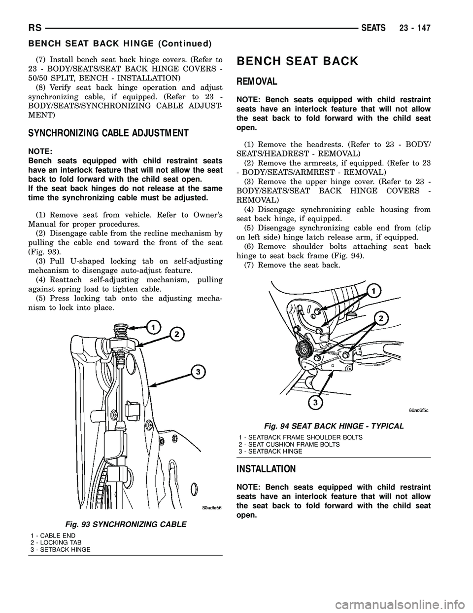
(2) Disengage cable from the recline mechanism by
pulling the cable end toward the front of the seat
(Fig. 93).
(3) Pull U-shaped locking tab on self-adjusting
mehcanism to disengage auto-adjust feature.
(4) Reattach self-adjusting mechanism, pulling
against spring load to tighten cable.
(5) Press locking tab onto the adjusting mecha-
nism to lock into place.
BENCH SEAT BACK
REMOVAL
NOTE: Bench seats equipped with child restraint
seats have an interlock feature that will not allow
the seat back to fold forward with the child seat
open.
(1) Remove the headrests. (Refer to 23 - BODY/
SEATS/HEADREST - REMOVAL)
(2) Remove the armrests, if equipped. (Refer to 23
- BODY/SEATS/ARMREST - REMOVAL)
(3) Remove the upper hinge cover. (Refer to 23 -
BODY/SEATS/SEAT BACK HINGE COVERS -
REMOVAL)
(4) Disengage synchronizing cable housing from
seat back hinge, if equipped.
(5) Disengage synchronizing cable end from (clip
on left side) hinge latch release arm, if equipped.
(6) Remove shoulder bolts attaching seat back
hinge to seat back frame (Fig. 94).
(7) Remove the seat back.
INSTALLATION
NOTE: Bench seats equipped with child restraint
seats have an interlock feature that will not allow
the seat back to fold forward with the child seat
open.
Fig. 93 SYNCHRONIZING CABLE
1 - CABLE END
2 - LOCKING TAB
3 - SETBACK HINGE
Fig. 94 SEAT BACK HINGE - TYPICAL
1 - SEATBACK FRAME SHOULDER BOLTS
2 - SEAT CUSHION FRAME BOLTS
3 - SEATBACK HINGE
RSSEATS23 - 147
BENCH SEAT BACK HINGE (Continued)
Page 1930 of 2339

SEAT RISER LATCH LOCKING
LINK
REMOVAL
(1) Remove seat as necessary to access latch lock-
ing link.
NOTE: If the seat is locked in the seated position
and cannot be tilted forward, it can be released by
reaching into the escutcheons with a hook tool or a
finger from the rear. Pulling the latch toward the
rear of the vehicle will unlock the seat latch allow-
ing the seat to tilt forward.
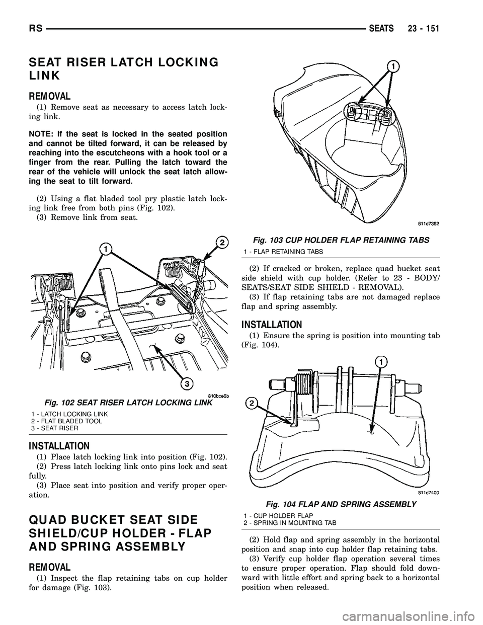
(2) Using a flat bladed tool pry plastic latch lock-
ing link free from both pins (Fig. 102).
(3) Remove link from seat.
INSTALLATION
(1) Place latch locking link into position (Fig. 102).
(2) Press latch locking link onto pins lock and seat
fully.
(3) Place seat into position and verify proper oper-
ation.
QUAD BUCKET SEAT SIDE
SHIELD/CUP HOLDER - FLAP
AND SPRING ASSEMBLY
REMOVAL
(1) Inspect the flap retaining tabs on cup holder
for damage (Fig. 103).(2) If cracked or broken, replace quad bucket seat
side shield with cup holder. (Refer to 23 - BODY/
SEATS/SEAT SIDE SHIELD - REMOVAL).
(3) If flap retaining tabs are not damaged replace
flap and spring assembly.
INSTALLATION
(1) Ensure the spring is position into mounting tab
(Fig. 104).
(2)
Hold flap and spring assembly in the horizontal
position and snap into cup holder flap retaining tabs.
(3) Verify cup holder flap operation several times
to ensure proper operation. Flap should fold down-
ward with little effort and spring back to a horizontal
position when released.
Fig. 102 SEAT RISER LATCH LOCKING LINK
1 - LATCH LOCKING LINK
2 - FLAT BLADED TOOL
3 - SEAT RISER
Fig. 103 CUP HOLDER FLAP RETAINING TABS
1 - FLAP RETAINING TABS
Fig. 104 FLAP AND SPRING ASSEMBLY
1 - CUP HOLDER FLAP
2 - SPRING IN MOUNTING TAB
RSSEATS23 - 151
Page 1931 of 2339
BOTTOM OF SEAT CUSHION
PAN PANEL-THIRD ROW -
FOLD-IN-FLOOR
REMOVAL
(1) Fold the third row seat with back down.
(2) Remove handle from cushion.
(3) Using a trim tool, remove bottom side of the
cushion pan panel (Fig. 105).
INSTALLATION
(1) Place bottom side of the cushion pan panel into
position (Fig. 106).
(2) Press on back of cushion pan panel to seat the
fasteners.
(3) Install handle on cushion.
(4) Place seat in the up right position.
HEADREST SLEEVE - THIRD
ROW - FOLD-IN-FLOOR
REMOVAL
(1) Remove headrest (Fig. 107).
(2) Using a trim tool remove sleeve by prying
sleeve away from the seat back frame to unlock it
(Fig. 108)
(3) Pull headrest sleeve upward and out the top of
the seat back frame and remove from seat.
Fig. 105 THIRD ROW CUSHION PAN & COVER
Fig. 106 THIRD ROW CUSHION PAN & COVER
Fig. 107 HEADREST
1 - HEADREST
2 - DEPRESS TAB
Fig. 108 REMOVING HEADREST SLEEVES
1 - HEADREST SLEEVES
2 - TRIM TOOL
23 - 152 SEATSRS