Page 1884 of 2339
INSTALLATION
INSTALLATION
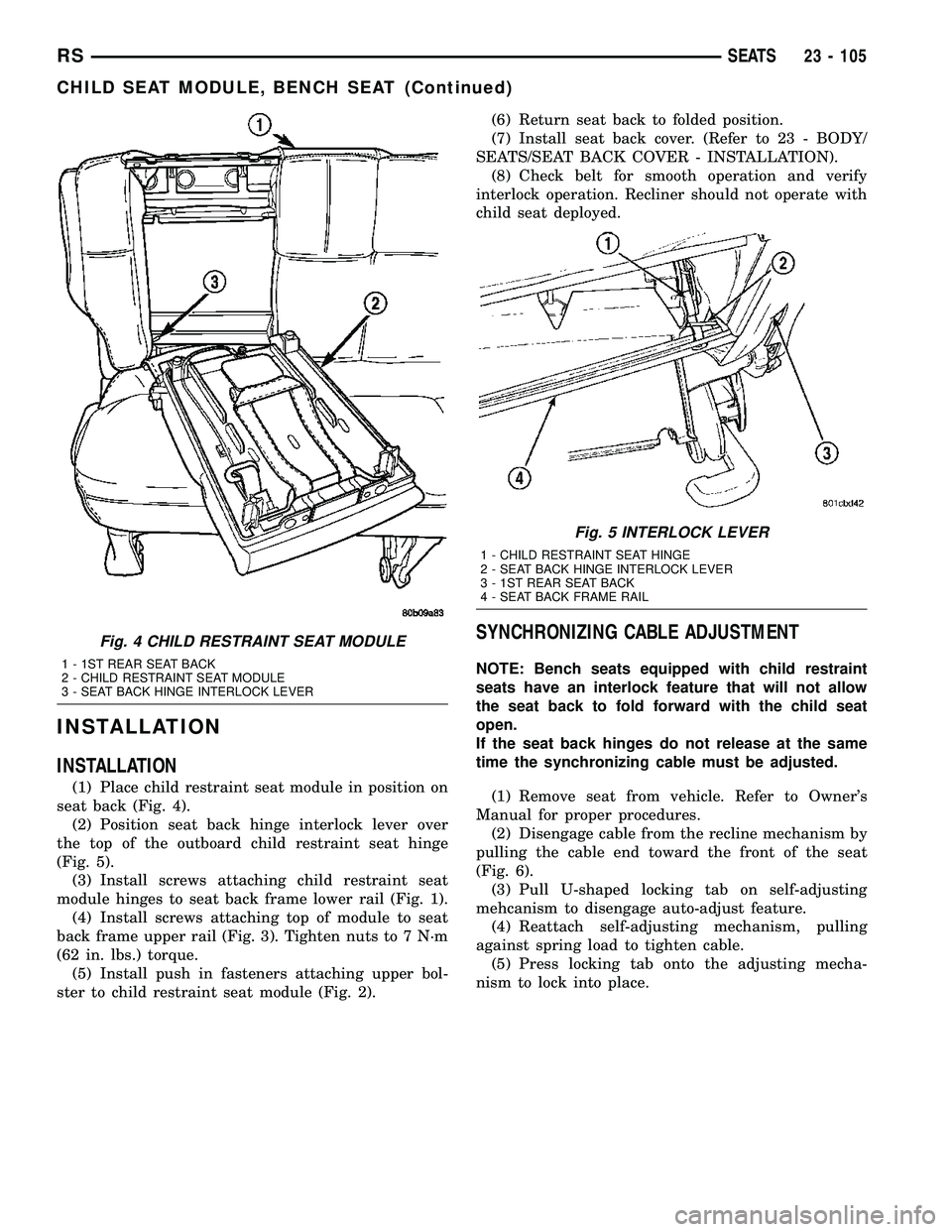
(1) Place child restraint seat module in position on
seat back (Fig. 4).
(2) Position seat back hinge interlock lever over
the top of the outboard child restraint seat hinge
(Fig. 5).
(3) Install screws attaching child restraint seat
module hinges to seat back frame lower rail (Fig. 1).
(4) Install screws attaching top of module to seat
back frame upper rail (Fig. 3). Tighten nuts to 7 N´m
(62 in. lbs.) torque.
(5) Install push in fasteners attaching upper bol-
ster to child restraint seat module (Fig. 2).(6) Return seat back to folded position.
(7) Install seat back cover. (Refer to 23 - BODY/
SEATS/SEAT BACK COVER - INSTALLATION).
(8) Check belt for smooth operation and verify
interlock operation. Recliner should not operate with
child seat deployed.
SYNCHRONIZING CABLE ADJUSTMENT
NOTE: Bench seats equipped with child restraint
seats have an interlock feature that will not allow
the seat back to fold forward with the child seat
open.
If the seat back hinges do not release at the same
time the synchronizing cable must be adjusted.
(1) Remove seat from vehicle. Refer to Owner's
Manual for proper procedures.
(2) Disengage cable from the recline mechanism by
pulling the cable end toward the front of the seat
(Fig. 6).
(3) Pull U-shaped locking tab on self-adjusting
mehcanism to disengage auto-adjust feature.
(4) Reattach self-adjusting mechanism, pulling
against spring load to tighten cable.
(5) Press locking tab onto the adjusting mecha-
nism to lock into place.
Fig. 4 CHILD RESTRAINT SEAT MODULE
1 - 1ST REAR SEAT BACK
2 - CHILD RESTRAINT SEAT MODULE
3 - SEAT BACK HINGE INTERLOCK LEVER
Fig. 5 INTERLOCK LEVER
1 - CHILD RESTRAINT SEAT HINGE
2 - SEAT BACK HINGE INTERLOCK LEVER
3 - 1ST REAR SEAT BACK
4 - SEAT BACK FRAME RAIL
RSSEATS23 - 105
CHILD SEAT MODULE, BENCH SEAT (Continued)
Page 1909 of 2339
WARNING: TO AVOID PERSONAL INJURY OR
DEATH ON VEHICLES EQUIPPED WITH THE OCCU-
PANT CLASSIFICATION SYSTEM (OCS), ONLY THE
OCCUPANT CLASSIFICATION MODULE (OCM) AND
THE SEAT CUSHION TRIM MAY BE SERVICED SEP-
ARATELY. ALL OTHER COMPONENTS OF THE PAS-
SENGER SIDE FRONT SEAT CUSHION ASSEMBLY
MUST BE SERVICED ONLY AS A COMPLETE FAC-
TORY-CALIBRATED, ASSEMBLED AND TAMPER-EV-
IDENT SERVICE REPLACEMENT PACKAGE. THIS
PACKAGE INCLUDES THE FRAME, SPRINGS, PAD,
BLADDER, SENSOR, FOAM, WIRING AND A CALI-
BRATED OCM. WHEN INSTALLING THIS PACKAGE
ALWAYS REPLACE ALL OF THE EXISTING COMPO-
NENTS WITH THE NEW COMPONENTS AS A UNIT.
DO NOT ATTEMPT TO SEPARATE OR DISCONNECT
ANY OF THE NEW OCS COMPONENTS IN THE SER-
VICE REPLACEMENT PACKAGE FROM EACH
OTHER, AND DO NOT ATTEMPT TO REUSE ANY OF
THE REPLACED COMPONENTS IN THIS OR ANY
OTHER VEHICLE. FAILURE TO TAKE THE PROPER
PRECAUTIONS COULD RESULT IN FAILURE OF
THE PASSENGER AIRBAG TO DEPLOY WHEN
REQUIRED, OR IN PASSENGER AIRBAG DEPLOY-
MENT WHEN NOT REQUIRED.
(1) Place rear cover in position on seat.
(2) Engage fasteners attaching rear cover to slots
on power seat track.
(3) Engage arrowhead retainer into loop strip
attaching rear cover to power seat track crossbar
(Fig. 42).
ARMREST - SECOND ROW -
FOLD-IN-FLOOR
REMOVAL
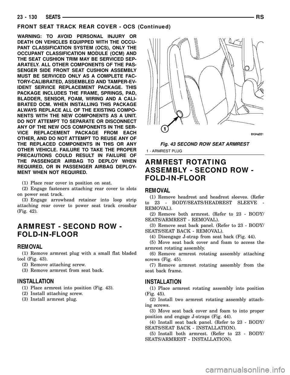
(1) Remove armrest plug with a small flat bladed
tool (Fig. 43).
(2) Remove attaching screw.
(3) Remove armrest from seat back.
INSTALLATION
(1) Place armrest into position (Fig. 43).
(2) Install attaching screw.
(3) Install armrest plug.
ARMREST ROTATING
ASSEMBLY - SECOND ROW -
FOLD-IN-FLOOR
REMOVAL
(1) Remove headrest and headrest sleeves. (Refer
to 23 - BODY/SEATS/HEADREST SLEEVE -
REMOVAL).
(2) Remove both armrest. (Refer to 23 - BODY/
SEATS/ARMREST - REMOVAL).
(3) Remove seat back panel. (Refer to 23 - BODY/
SEATS/SEAT BACK - REMOVAL).
(4) Disengage J-strap from seat back (Fig. 44).
(5) Move seat back cover and foam to access the
armrest rotating assembly.
(6) Remove armrest rotating assembly attaching
screws (Fig. 45).
(7) Remove armrest rotating assembly from the
seat back frame.
INSTALLATION
(1) Place armrest rotating assembly into position
(Fig. 45).
(2) Install two armrest rotating assembly attach-
ing screws.
(3) Move seat back cover and foam to into proper
position and engage J-straps (Fig. 44).
(4) Install seat back panel. (Refer to 23 - BODY/
SEATS/SEAT BACK - INSTALLATION).
(5) Install both armrest. (Refer to 23 - BODY/
SEATS/ARMREST - INSTALLATION).
Fig. 43 SECOND ROW SEAT ARMREST
1 - ARMREST PLUG
23 - 130 SEATSRS
FRONT SEAT TRACK REAR COVER - OCS (Continued)
Page 1910 of 2339
(6) Install headrest sleeves and headrest. (Refer to
23 - BODY/SEATS/HEADREST SLEEVE - INSTAL-
LATION).
HEADREST SLEEVE - SECOND
ROW - FOLD-IN-FLOOR
REMOVAL
(1) Remove headrest (Fig. 46).(2) Using a trim tool remove sleeve by prying
sleeve away from the seat back frame to unlock it
(Fig. 47).
(3) Pull headrest sleeve upward and out the top of
the seat back frame and remove from seat.
INSTALLATION
(1) Place headrest sleeve into position and push
downward until sleeve locks into position.
(2) Install headrest (Fig. 46).
Fig. 44 SECOND ROW SEAT BACK
1 - J-STRAPS
Fig. 45 SECOND ROW ARMREST ROTATING
ASSEMBLY
1 - ATTACHING SCREWS
Fig. 46 HEADREST
1 - HEADREST
2 - DEPRESS TAB
Fig. 47 HEADREST SLEEVE
1 - REMOVE SLEEVE
RSSEATS23 - 131
ARMREST ROTATING ASSEMBLY - SECOND ROW - FOLD-IN-FLOOR (Continued)
Page 1911 of 2339
SEAT - SECOND ROW -
FOLD-IN-FLOOR
REMOVAL
(1) Fold second row seats into floor well (Fig. 48).
(2) Place special tool # 9313 R1 on seat shaft (Fig.
49) and (Fig. 50).
(3) Raise seat to the unsprung position and remove
the three attaching nuts (Fig. 51).(4) Pick seat up out of floor well and remove from
vehicle.
INSTALLATION
(1) Place second row seat into position in floor
well.
(2) Install the three attaching nuts. Tighten nuts
to 54 N´m (40 ft. lbs.) torque.
(3) Remove Special Tool # 9313 R1 from seat shaft
(Fig. 50) and (Fig. 49).
(4) Raise seat to upright position (Fig. 48).
Fig. 48 SECOND ROW SEATS - FOLD-IN-FLOOR
1 - ATTACHING NUTS
2 - SEATS IN THE UPRIGHT POSITION
Fig. 49 PLACING TOOL IN TO POSITION
1 - SPECIAL TOOL # 9313 R1
Fig. 50 TOOL IN POSITION
Fig. 51 SEAT IN UNSPRUNG POSITION
1 - ATTACHING NUTS
23 - 132 SEATSRS
Page 1912 of 2339
SEAT BACK COVER/FOAM -
SECOND ROW - FOLD-IN-
FLOOR
REMOVAL
(1) Remove both armrest. (Refer to 23 - BODY/
SEATS/ARMREST - REMOVAL).
(2) Remove headrest and headrest sleeves. (Refer
to 23 - BODY/SEATS/HEADREST SLEEVE -
REMOVAL).
(3) Remove seat back panel. (Refer to 23 - BODY/
SEATS/SEAT BACK PANEL - REMOVAL).
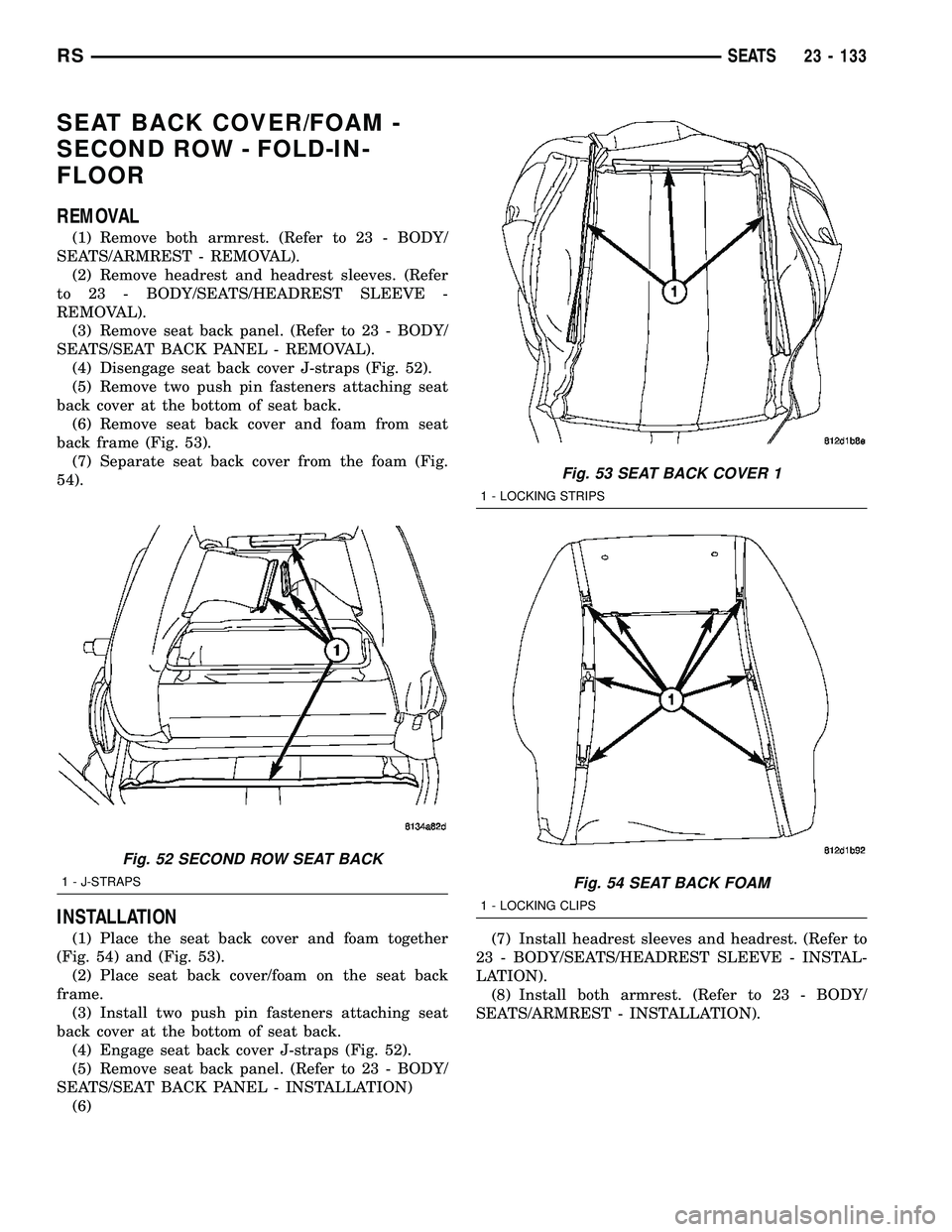
(4) Disengage seat back cover J-straps (Fig. 52).
(5) Remove two push pin fasteners attaching seat
back cover at the bottom of seat back.
(6) Remove seat back cover and foam from seat
back frame (Fig. 53).
(7) Separate seat back cover from the foam (Fig.
54).
INSTALLATION
(1) Place the seat back cover and foam together
(Fig. 54) and (Fig. 53).
(2) Place seat back cover/foam on the seat back
frame.
(3) Install two push pin fasteners attaching seat
back cover at the bottom of seat back.
(4) Engage seat back cover J-straps (Fig. 52).
(5) Remove seat back panel. (Refer to 23 - BODY/
SEATS/SEAT BACK PANEL - INSTALLATION)
(6)(7) Install headrest sleeves and headrest. (Refer to
23 - BODY/SEATS/HEADREST SLEEVE - INSTAL-
LATION).
(8) Install both armrest. (Refer to 23 - BODY/
SEATS/ARMREST - INSTALLATION).
Fig. 52 SECOND ROW SEAT BACK
1 - J-STRAPS
Fig. 53 SEAT BACK COVER 1
1 - LOCKING STRIPS
Fig. 54 SEAT BACK FOAM
1 - LOCKING CLIPS
RSSEATS23 - 133
Page 1913 of 2339
SEAT BACK FRAME - SECOND
ROW - FOLD-IN-FLOOR
REMOVAL
(1) Remove seat back cover and foam. (Refer to 23
- BODY/SEATS/SEAT BACK COVER/FOAM -
REMOVAL).
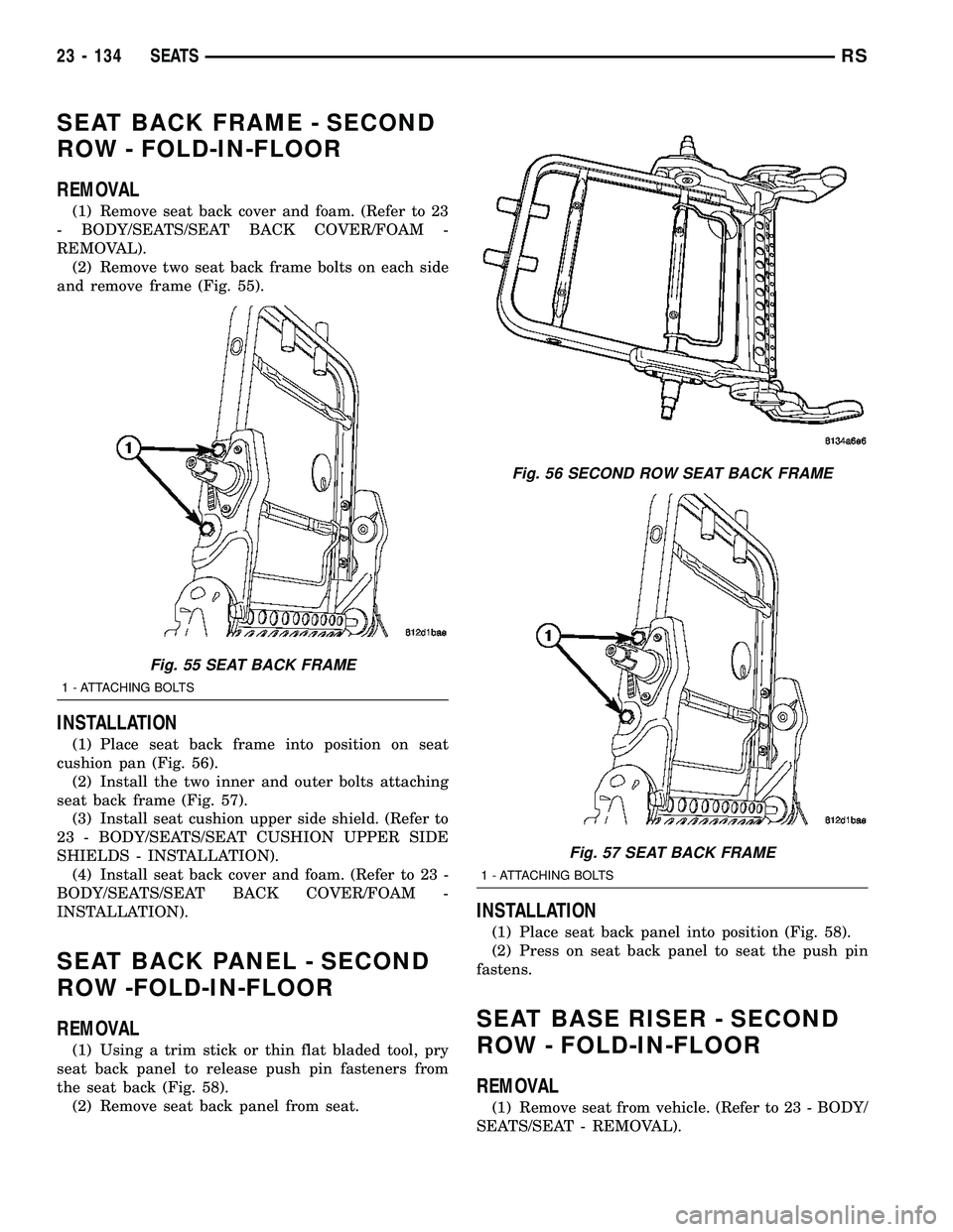
(2) Remove two seat back frame bolts on each side
and remove frame (Fig. 55).
INSTALLATION
(1) Place seat back frame into position on seat
cushion pan (Fig. 56).
(2) Install the two inner and outer bolts attaching
seat back frame (Fig. 57).
(3) Install seat cushion upper side shield. (Refer to
23 - BODY/SEATS/SEAT CUSHION UPPER SIDE
SHIELDS - INSTALLATION).
(4) Install seat back cover and foam. (Refer to 23 -
BODY/SEATS/SEAT BACK COVER/FOAM -
INSTALLATION).
SEAT BACK PANEL - SECOND
ROW -FOLD-IN-FLOOR
REMOVAL
(1) Using a trim stick or thin flat bladed tool, pry
seat back panel to release push pin fasteners from
the seat back (Fig. 58).
(2) Remove seat back panel from seat.
INSTALLATION
(1) Place seat back panel into position (Fig. 58).
(2) Press on seat back panel to seat the push pin
fastens.
SEAT BASE RISER - SECOND
ROW - FOLD-IN-FLOOR
REMOVAL
(1) Remove seat from vehicle. (Refer to 23 - BODY/
SEATS/SEAT - REMOVAL).
Fig. 55 SEAT BACK FRAME
1 - ATTACHING BOLTS
Fig. 56 SECOND ROW SEAT BACK FRAME
Fig. 57 SEAT BACK FRAME
1 - ATTACHING BOLTS
23 - 134 SEATSRS
Page 1914 of 2339
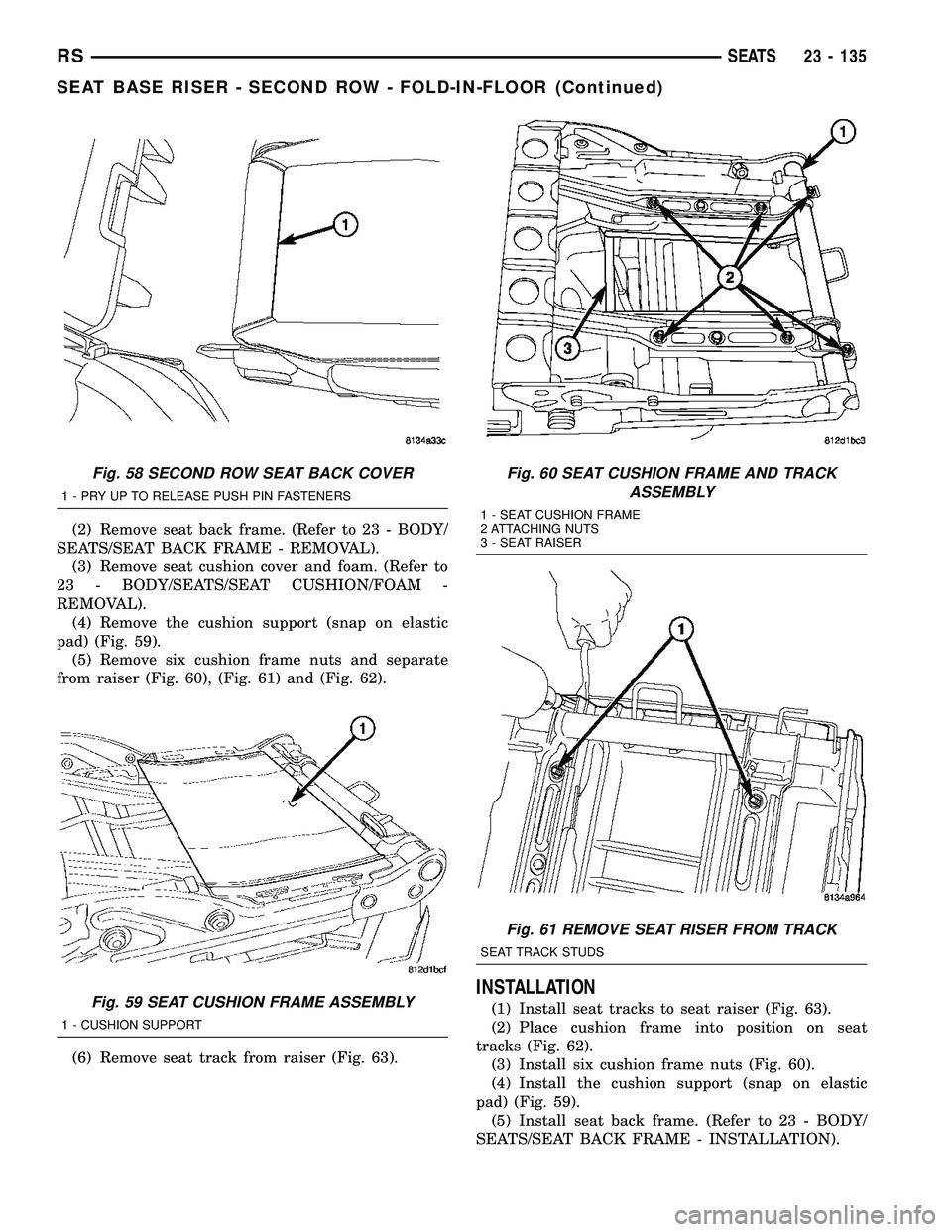
(2) Remove seat back frame. (Refer to 23 - BODY/
SEATS/SEAT BACK FRAME - REMOVAL).
(3) Remove seat cushion cover and foam. (Refer to
23 - BODY/SEATS/SEAT CUSHION/FOAM -
REMOVAL).
(4) Remove the cushion support (snap on elastic
pad) (Fig. 59).
(5) Remove six cushion frame nuts and separate
from raiser (Fig. 60), (Fig. 61) and (Fig. 62).
(6) Remove seat track from raiser (Fig. 63).
INSTALLATION
(1) Install seat tracks to seat raiser (Fig. 63).
(2) Place cushion frame into position on seat
tracks (Fig. 62).
(3) Install six cushion frame nuts (Fig. 60).
(4) Install the cushion support (snap on elastic
pad) (Fig. 59).
(5) Install seat back frame. (Refer to 23 - BODY/
SEATS/SEAT BACK FRAME - INSTALLATION).
Fig. 58 SECOND ROW SEAT BACK COVER
1 - PRY UP TO RELEASE PUSH PIN FASTENERS
Fig. 59 SEAT CUSHION FRAME ASSEMBLY
1 - CUSHION SUPPORT
Fig. 60 SEAT CUSHION FRAME AND TRACK
ASSEMBLY
1 - SEAT CUSHION FRAME
2 ATTACHING NUTS
3 - SEAT RAISER
Fig. 61 REMOVE SEAT RISER FROM TRACK
SEAT TRACK STUDS
RSSEATS23 - 135
SEAT BASE RISER - SECOND ROW - FOLD-IN-FLOOR (Continued)
Page 1915 of 2339

(6) Install seat cushion cover and foam. (Refer to
23 - BODY/SEATS/SEAT CUSHION/FOAM -
INSTALLATION).
SEAT CUSHION COVER/FOAM
-SECOND ROW - FOLD-IN-
FLOOR
REMOVAL
(1) Remove seat cushion upper cushion side
shields. (Refer to 23 - BODY/SEATS/SEAT UPPER
CUSHION SIDE SHIELDS - REMOVAL)(2) Disengage J-straps attaching seat cushion
cover to cushion pan (Fig. 64).
(3) Remove seat cushion cover and foam from
cushion pan (Fig. 65).
(4) Separate the seat cushion cover from the foam.
INSTALLATION
(1) Place the seat cushion cover and foam together
and place on seat cushion pan (Fig. 65).
(2) Engage J-straps attaching seat cushion cover to
cushion pan (Fig. 64).
(3) Install seat cushion upper cushion side shields.
(Refer to 23 - BODY/SEATS/SEAT UPPER CUSH-
ION SIDE SHIELDS - INSTALLATION).
Fig. 62 SECOND ROW SEAT RISER
1 - SEAT RISER ASSEMBLY
Fig. 63 SEAT TRACK
1 - SEAT TRACK
2 - ATTACHING STUDS
Fig. 64 SECOND ROW CUSHION ATTACHING
POINTS
1 - J-STRAPS
Fig. 65 SECOND ROW SEAT CUSHION ASSEMBLY
23 - 136 SEATSRS
SEAT BASE RISER - SECOND ROW - FOLD-IN-FLOOR (Continued)