2005 CHRYSLER CARAVAN oil filter
[x] Cancel search: oil filterPage 35 of 2339

At Each Oil Change
²Change the engine oil filter.
²Inspect the exhaust system.
²Inspect the brake hoses.
²Inspect the CV joints and front suspension com-
ponents.²Check the manual transmission fluid level.
²Check the coolant level, hoses, and clamps.
²Inspect engine accessory drive belts. Replace as
necessary.
²Inspect for the presence of water in the fuel fil-
ter/water separator unit.
SCHEDULE A - DIESEL ENGINES
Kilometers 20 000 km 40 000 km 60 000 km 80 000 km 100 000
km
Change engine oil and engine oil filter.XXXX X
Rotate TiresXXXX X
Replace engine air filter elementXXXX X
Replace fuel filter/water separator unit.XXXX X
Inspect timing belt tensioner. ³X
Replace the engine timing belt and idler
pulleys.X
Check front end alignment. X X
Inspect the tie rod ends and boot seals. X X
Inspect the brake linings.XXXX X
Kilometers 120 000
km140 000
km160 000
km180 000
km200 000
km
Change engine oil and engine oil filter.XXXXX
Rotate TiresXXXX X
Inspect accessory drive belts and replace if
necessary.X
Replace engine air filter elementXXXX X
Replace fuel filter/water separator unit.XXXXX
Replace the timing belt, idler pulleys and
timing belt tensioner.X
Flush and replace engine coolant. X
Check front end alignment. X X X
Inspect the tie rod ends and boot seals. X X X
Inspect the brake linings.XXXXX
Inspection and service should also be performed
anytime a malfunction is observed or suspected.
Retain all receipts.³ Replace if there is superficial wear, bearing clear-
ance, or evident grease leakage.
0 - 22 LUBRICATION & MAINTENANCERS
MAINTENANCE SCHEDULES (Continued)
Page 36 of 2339

SCHEDULE B - DIESEL ENGINES
Follow schedule ªBº if you usually operate your
vehicle under one or more of the following conditions.
²Extensive engine idling.
²Driving in dusty conditions.²More than 50% of your driving is at sustained
high speeds during hot weather, above 32É C (90É F).
²Trailer towing.
²Taxi, police, or delivery service (commercial ser-
vice).
Kilometers 10 000 km 20 000 km 30 000 km 40 000 km 50 000 km
Change engine oil and engine oil filter.XXXX X
Rotate Tires X X
Replace engine air filter elementXXXX X
Replace engine accessory drive belt. X
Replace the engine timing belt and idler
pulleys.X
Inspect timing belt tensioner. ³X
Replace fuel filter/water separator unit. X X
Check front end alignment. X X
Change the manual transaxle fluid. X
Inspect the tie rod ends and boot seals. X
Inspect the brake linings.XXXX X
Kilometers 60 000 km 70 000 km 80 000 km 90 000 km 100 000
km
Change engine oil and engine oil filter.XXXX X
Rotate Tires X X X
Replace engine air filter elementXXXX X
Replace fuel filter/water separator unit. X X X
Replace engine accessory drive belt. X
Replace engine timing belt, idler pulleys
and timing belt tensioner.X
Check front end alignment. X X
Change the manual transaxle fluid. X X
Inspect the tie rod ends and boot seals. X
Inspect the brake linings.XXXX X
Kilometers 110 000
km120 000
km130 000
km140 000
km150 000
km160 000
km
Change engine oil and engine
oil filter.XXXXX X
Rotate Tires X X X
Replace engine air filter
elementXXXXX X
Replace engine accessory
drive belt.X
Replace the engine timing
belt and idler pulleys.X
Inspect timing belt tensioner.
³X
RSLUBRICATION & MAINTENANCE0-23
MAINTENANCE SCHEDULES (Continued)
Page 374 of 2339

INSTRUMENT CLUSTER
TABLE OF CONTENTS
page page
INSTRUMENT CLUSTER
DESCRIPTION..........................1
OPERATION............................1
DIAGNOSIS AND TESTING
DIAGNOSIS AND TESTING - SELF-
DIAGNOSTICS.........................2
DIAGNOSIS AND TESTING - CLUSTER
DIAGNOSIS...........................3REMOVAL.............................11
INSTALLATION.........................11
CLUSTER LENS
REMOVAL.............................11
INSTALLATION.........................11
INSTRUMENT CLUSTER
DESCRIPTION
The instrumentation gauges are contained in a
subdial assembly within the instrument cluster. The
individual gauges are not serviceable. If one of the
cluster gauges becomes faulty, the entire cluster
would require replacement.
The Mechanical Instrument Cluster (MIC) with a
tachometer is equipped with a electronic vacuum flu-
orescent transmission range indicator (PRND3L),
odometer, and trip odometer display.
The MIC without a tachometer is equipped with a
Light Emitting Diode (LED) transmission range indi-
cator (PRND3L) and a vacuum fluorescent odometer
display.
The MIC is equipped with the following warning
lamps.
²Lift Gate Ajar
²Low Fuel Level
²Low Windshield Washer Fluid Level
²Cruise
²Battery Voltage
²Fasten Seat Belt
²Door Ajar
²Coolant Temperature
²Anti-Lock Brake
²Brake
²Oil Pressure
²MIL (Malfunction Indicator Lamp)
²VTSS/SKIS Indicator
²Airbag
²Traction Control
²Autostick
Export Only- uses a message center that displays
the following telltales:
²Turns Signals
²High Beam
²Tire Pressure Monitoring (TPM)²Glow Plug (Export Only)
²Supplemental Cabin Heater (Export Only)WATER IN FUEL LAMP - EXPORT
The Water In Fuel Lamp is located in the message
center. When moisture is found within the fuel sys-
tem, the sensor sends a message via the PCI data
bus to the instrument cluster. The MIC illuminates
the bulb in the message center, The sensor is located
underneath the vehicle, directly above the rear axle.
The sensor is housed within the fuel filter/water sep-
arator assembly cover. The sensor is not serviced sep-
arately. If found defective, the entire assembly cover
must be replaced.
OPERATION
Refer to the vehicle Owner's Manual for operation
instructions and conditions for the Instrument Clus-
ter Gauges.
WATER IN FUEL LAMP/SENSOR - EXPORT
The Water In Fuel Sensor is a resistive type
switch. It is calibrated to sense the different resis-
tance between diesel fuel and water. When water
enters the fuel system, it is caught in the bottom of
the fuel filter/water separator assembly, where the
sensor is located. Water has less resistance than die-
sel fuel. The sensor then sends a PCI data bus mes-
sage to the instrument cluster to illuminate the
lamp.
If the lamp is inoperative, perform the self diag-
nostic test on the instrument cluster to check the
lamp operation before continuing diagnosis.
RSINSTRUMENT CLUSTER8J-1
Page 1179 of 2339
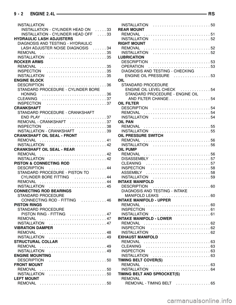
INSTALLATION
INSTALLATION - CYLINDER HEAD ON.....33
INSTALLATION - CYLINDER HEAD OFF....33
HYDRAULIC LASH ADJUSTERS
DIAGNOSIS AND TESTING - HYDRAULIC
LASH ADJUSTER NOISE DIAGNOSIS......34
REMOVAL.............................35
INSTALLATION.........................35
ROCKER ARMS
REMOVAL.............................35
INSPECTION..........................35
INSTALLATION.........................35
ENGINE BLOCK
DESCRIPTION.........................36
STANDARD PROCEDURE - CYLINDER BORE
HONING............................36
CLEANING............................37
INSPECTION..........................37
CRANKSHAFT
STANDARD PROCEDURE - CRANKSHAFT
ENDPLAY ...........................37
REMOVAL - CRANKSHAFT................37
INSPECTION..........................38
INSTALLATION - CRANKSHAFT............39
CRANKSHAFT OIL SEAL - FRONT
REMOVAL.............................41
INSTALLATION.........................42
CRANKSHAFT OIL SEAL - REAR
REMOVAL.............................42
INSTALLATION.........................42
PISTON & CONNECTING ROD
DESCRIPTION.........................44
STANDARD PROCEDURE - PISTON TO
CYLINDER BORE FITTING..............44
REMOVAL.............................44
INSTALLATION.........................45
CONNECTING ROD BEARINGS
STANDARD PROCEDURE
CONNECTING ROD - FITTING...........46
PISTON RINGS
STANDARD PROCEDURE
PISTON RING - FITTING................47
REMOVAL.............................47
INSTALLATION.........................47
VIBRATION DAMPER
REMOVAL.............................48
INSTALLATION.........................49
STRUCTURAL COLLAR
REMOVAL.............................49
INSTALLATION.........................49
ENGINE MOUNTING
DESCRIPTION.........................50
FRONT MOUNT
REMOVAL.............................50
INSTALLATION.........................50
LEFT MOUNT
REMOVAL.............................50INSTALLATION.........................50
REAR MOUNT
REMOVAL.............................51
INSTALLATION.........................52
RIGHT MOUNT
REMOVAL.............................52
INSTALLATION.........................52
LUBRICATION
DESCRIPTION.........................53
OPERATION...........................53
DIAGNOSIS AND TESTING - CHECKING
ENGINE OIL PRESSURE................53
OIL
STANDARD PROCEDURE
ENGINE OIL LEVEL CHECK.............54
STANDARD PROCEDURE - ENGINE OIL
AND FILTER CHANGE..................54
OIL FILTER
DESCRIPTION.........................54
REMOVAL.............................54
INSTALLATION.........................54
OIL PAN
REMOVAL.............................55
INSTALLATION.........................55
OIL PRESSURE SWITCH
REMOVAL.............................56
INSTALLATION.........................56
OIL PUMP
REMOVAL.............................56
DISASSEMBLY.........................57
CLEANING............................57
INSPECTION..........................58
ASSEMBLY............................58
INSTALLATION.........................59
INTAKE MANIFOLD
DESCRIPTION.........................60
DIAGNOSIS AND TESTING - INTAKE
MANIFOLD LEAKS.....................60
INTAKE MANIFOLD - UPPER
REMOVAL.............................60
INSPECTION..........................61
INSTALLATION.........................61
INTAKE MANIFOLD - LOWER
REMOVAL.............................62
INSPECTION..........................62
INSTALLATION.........................62
EXHAUST MANIFOLD
REMOVAL.............................63
CLEANING............................63
INSPECTION..........................63
INSTALLATION.........................63
TIMING BELT COVER(S)
REMOVAL.............................63
INSTALLATION.........................64
TIMING BELT AND SPROCKET(S)
REMOVAL
REMOVAL - TIMING BELT...............65
9 - 2 ENGINE 2.4LRS
Page 1181 of 2339
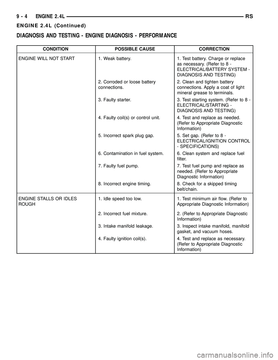
DIAGNOSIS AND TESTING - ENGINE DIAGNOSIS - PERFORMANCE
CONDITION POSSIBLE CAUSE CORRECTION
ENGINE WILL NOT START 1. Weak battery. 1. Test battery. Charge or replace
as necessary. (Refer to 8 -
ELECTRICAL/BATTERY SYSTEM -
DIAGNOSIS AND TESTING)
2. Corroded or loose battery
connections.2. Clean and tighten battery
connections. Apply a coat of light
mineral grease to terminals.
3. Faulty starter. 3. Test starting system. (Refer to 8 -
ELECTRICAL/STARTING -
DIAGNOSIS AND TESTING)
4. Faulty coil(s) or control unit. 4. Test and replace as needed.
(Refer to Appropriate Diagnostic
Information)
5. Incorrect spark plug gap. 5. Set gap. (Refer to 8 -
ELECTRICAL/IGNITION CONTROL
- SPECIFICATIONS)
6. Contamination in fuel system. 6. Clean system and replace fuel
filter.
7. Faulty fuel pump. 7. Test fuel pump and replace as
needed. (Refer to Appropriate
Diagnostic Information)
8. Incorrect engine timing. 8. Check for a skipped timing
belt/chain.
ENGINE STALLS OR IDLES
ROUGH1. Idle speed too low. 1. Test minimum air flow. (Refer to
Appropriate Diagnostic Information)
2. Incorrect fuel mixture. 2. (Refer to Appropriate Diagnostic
Information)
3. Intake manifold leakage. 3. Inspect intake manifold, manifold
gasket, and vacuum hoses.
4. Faulty ignition coil(s). 4. Test and replace as necessary.
(Refer to Appropriate Diagnostic
Information)
9 - 4 ENGINE 2.4LRS
ENGINE 2.4L (Continued)
Page 1182 of 2339
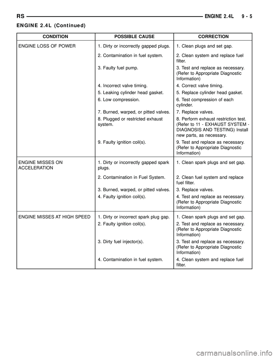
CONDITION POSSIBLE CAUSE CORRECTION
ENGINE LOSS OF POWER 1. Dirty or incorrectly gapped plugs. 1. Clean plugs and set gap.
2. Contamination in fuel system. 2. Clean system and replace fuel
filter.
3. Faulty fuel pump. 3. Test and replace as necessary.
(Refer to Appropriate Diagnostic
Information)
4. Incorrect valve timing. 4. Correct valve timing.
5. Leaking cylinder head gasket. 5. Replace cylinder head gasket.
6. Low compression. 6. Test compression of each
cylinder.
7. Burned, warped, or pitted valves. 7. Replace valves.
8. Plugged or restricted exhaust
system.8. Perform exhaust restriction test.
(Refer to 11 - EXHAUST SYSTEM -
DIAGNOSIS AND TESTING) Install
new parts, as necessary.
9. Faulty ignition coil(s). 9. Test and replace as necessary.
(Refer to Appropriate Diagnostic
Information)
ENGINE MISSES ON
ACCELERATION1. Dirty or incorrectly gapped spark
plugs.1. Clean spark plugs and set gap.
2. Contamination in Fuel System. 2. Clean fuel system and replace
fuel filter.
3. Burned, warped, or pitted valves. 3. Replace valves.
4. Faulty ignition coil(s). 4. Test and replace as necessary.
(Refer to Appropriate Diagnostic
Information)
ENGINE MISSES AT HIGH SPEED 1. Dirty or incorrect spark plug gap. 1. Clean spark plugs and set gap.
2. Faulty ignition coil(s). 2. Test and replace as necessary.
(Refer to Appropriate Diagnostic
Information)
3. Dirty fuel injector(s). 3. Test and replace as necessary.
(Refer to Appropriate Diagnostic
Information)
4. Contamination in fuel system. 4. Clean system and replace fuel
filter.
RSENGINE 2.4L9-5
ENGINE 2.4L (Continued)
Page 1183 of 2339
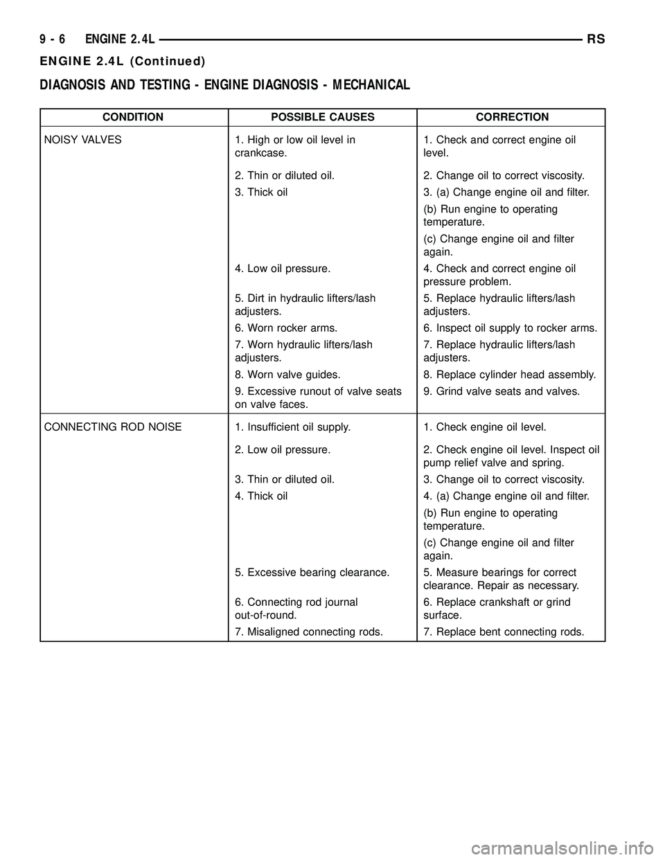
DIAGNOSIS AND TESTING - ENGINE DIAGNOSIS - MECHANICAL
CONDITION POSSIBLE CAUSES CORRECTION
NOISY VALVES 1. High or low oil level in
crankcase.1. Check and correct engine oil
level.
2. Thin or diluted oil. 2. Change oil to correct viscosity.
3. Thick oil 3. (a) Change engine oil and filter.
(b) Run engine to operating
temperature.
(c) Change engine oil and filter
again.
4. Low oil pressure. 4. Check and correct engine oil
pressure problem.
5. Dirt in hydraulic lifters/lash
adjusters.5. Replace hydraulic lifters/lash
adjusters.
6. Worn rocker arms. 6. Inspect oil supply to rocker arms.
7. Worn hydraulic lifters/lash
adjusters.7. Replace hydraulic lifters/lash
adjusters.
8. Worn valve guides. 8. Replace cylinder head assembly.
9. Excessive runout of valve seats
on valve faces.9. Grind valve seats and valves.
CONNECTING ROD NOISE 1. Insufficient oil supply. 1. Check engine oil level.
2. Low oil pressure. 2. Check engine oil level. Inspect oil
pump relief valve and spring.
3. Thin or diluted oil. 3. Change oil to correct viscosity.
4. Thick oil 4. (a) Change engine oil and filter.
(b) Run engine to operating
temperature.
(c) Change engine oil and filter
again.
5. Excessive bearing clearance. 5. Measure bearings for correct
clearance. Repair as necessary.
6. Connecting rod journal
out-of-round.6. Replace crankshaft or grind
surface.
7. Misaligned connecting rods. 7. Replace bent connecting rods.
9 - 6 ENGINE 2.4LRS
ENGINE 2.4L (Continued)
Page 1184 of 2339
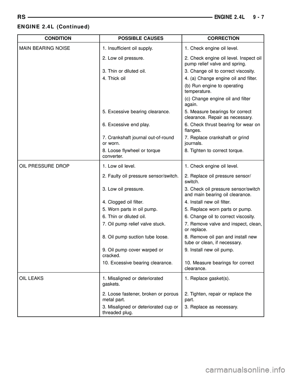
CONDITION POSSIBLE CAUSES CORRECTION
MAIN BEARING NOISE 1. Insufficient oil supply. 1. Check engine oil level.
2. Low oil pressure. 2. Check engine oil level. Inspect oil
pump relief valve and spring.
3. Thin or diluted oil. 3. Change oil to correct viscosity.
4. Thick oil 4. (a) Change engine oil and filter.
(b) Run engine to operating
temperature.
(c) Change engine oil and filter
again.
5. Excessive bearing clearance. 5. Measure bearings for correct
clearance. Repair as necessary.
6. Excessive end play. 6. Check thrust bearing for wear on
flanges.
7. Crankshaft journal out-of-round
or worn.7. Replace crankshaft or grind
journals.
8. Loose flywheel or torque
converter.8. Tighten to correct torque.
OIL PRESSURE DROP 1. Low oil level. 1. Check engine oil level.
2. Faulty oil pressure sensor/switch. 2. Replace oil pressure sensor/
switch.
3. Low oil pressure. 3. Check oil pressure sensor/switch
and main bearing oil clearance.
4. Clogged oil filter. 4. Install new oil filter.
5. Worn parts in oil pump. 5. Replace worn parts or pump.
6. Thin or diluted oil. 6. Change oil to correct viscosity.
7. Oil pump relief valve stuck. 7. Remove valve and inspect, clean,
or replace.
8. Oil pump suction tube loose. 8. Remove oil pan and install new
tube or clean, if necessary.
9. Oil pump cover warped or
cracked.9. Install new oil pump.
10. Excessive bearing clearance. 10. Measure bearings for correct
clearance.
OIL LEAKS 1. Misaligned or deteriorated
gaskets.1. Replace gasket(s).
2. Loose fastener, broken or porous
metal part.2. Tighten, repair or replace the
part.
3. Misaligned or deteriorated cup or
threaded plug.3. Replace as necessary.
RSENGINE 2.4L9-7
ENGINE 2.4L (Continued)