2005 CHRYSLER CARAVAN oil filter
[x] Cancel search: oil filterPage 1268 of 2339
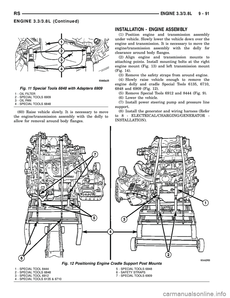
(60) Raise vehicle slowly. It is necessary to move
the engine/transmission assembly with the dolly to
allow for removal around body flanges.
INSTALLATION - ENGINE ASSEMBLY
(1) Position engine and transmission assembly
under vehicle. Slowly lower the vehicle down over the
engine and transmission. It is necessary to move the
engine/transmission assembly with the dolly for
clearance around body flanges.
(2) Align engine and transmission mounts to
attaching points. Install mounting bolts at the right
engine mount (Fig. 13) and left transmission mount
(Fig. 14).
(3) Remove the safety straps from around engine.
(4) Slowly raise vehicle enough to remove the
engine dolly and cradle Special Tools 6135, 6710,
6848 and 6909 (Fig. 12).
(5) Remove Special Tools 6912 and 8444 (Fig. 9).
(6) Lower the vehicle.
(7) Install power steering pump and pressure line
support.
(8) Install the generator and wiring harness (Refer
to 8 - ELECTRICAL/CHARGING/GENERATOR -
INSTALLATION).
Fig. 12 Positioning Engine Cradle Support Post Mounts
1 - SPECIAL TOOL 8444
2 - SPECIAL TOOLS 6848
3 - SPECIAL TOOL 6912
4 - SPECIAL TOOLS 6135 & 67105 - SPECIAL TOOLS 6848
6 - SAFETY STRAPS
7 - SPECIAL TOOLS 6909
Fig. 11 Special Tools 6848 with Adapters 6909
1 - OIL FILTER
2 - SPECIAL TOOLS 6909
3 - OIL PAN
4 - SPECIAL TOOLS 6848
RSENGINE 3.3/3.8L9-91
ENGINE 3.3/3.8L (Continued)
Page 1270 of 2339
(49) Install the radiator upper support crossmem-
ber (Refer to 23 - BODY/EXTERIOR/GRILLE OPEN-
ING REINFORCEMENT - INSTALLATION).
(50) Install the wiper module (Refer to 8 - ELEC-
TRICAL/WIPERS/WASHERS/WIPER MODULE -
INSTALLATION).
(51) Connect the fuel line to fuel rail (Refer to 14 -
FUEL SYSTEM/FUEL DELIVERY/FUEL LINES -
STANDARD PROCEDURE).
(52) Install the air cleaner and hoses.
(53) Install new oil filter. Fill engine crankcase
with proper oil to correct level.
(54) Connect negative cable to battery.
(55) Fill the cooling system (Refer to 7 - COOLING
- STANDARD PROCEDURE).
(56) Start engine and run until operating temper-
ature is reached.
(57) Adjust transmission linkage, if necessary.
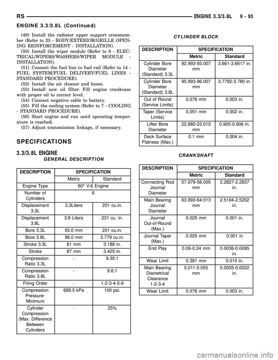
SPECIFICATIONS
3.3/3.8L ENGINE
GENERAL DESCRIPTION
DESCRIPTION SPECIFICATION
Metric Standard
Engine Type 60É V-6 Engine
Number of
Cylinders6
Displacement
3.3L3.3Liters 201 cu.in.
Displacement
3.8L3.8 Liters 231 cu. in.
Bore 3.3L 93.0 mm 201 cu.in.
Bore 3.8L 96.0 mm 3.779 cu.in.
Stroke 3.3L 81 mm 3.188 in.
Stroke 87 mm 3.425 in.
Compression
Ratio 3.3L- 9.35:1
Compression
Ratio 3.8L- 9.6:1
Firing Order - 1-2-3-4-5-6
Compression
Pressure-
Minimum689.5 kPa 100 psi.
Cylinder
Compression
(Max. Difference
Between
Cylinders- 25%
CYLINDER BLOCK
DESCRIPTION SPECIFICATION
Metric Standard
Cylinder Bore
Diameter
(Standard) 3.3L92.993-93.007
mm3.661-3.6617 in.
Cylinder Bore
Diameter
(Standard) 3.8L95.993-96.007
mm3.7792-3.780 in.
Out of Round
(Service Limits)0.076 mm 0.003 in.
Taper (Service
Limits)0.051 mm 0.002 in.
Lifter Bore
Diameter22.980-23.010
mm0.905-0.906 in.
Deck Surface
Flatness (Max.)0.1 mm 0.004 in.
CRANKSHAFT
DESCRIPTION SPECIFICATION
Metric Standard
Connecting Rod
Journal
Diameter57.979-58.005
mm2.2827-2.2837
in.
Main Bearing
Journal
Diameter63.993-64.013
mm2.5194-2.5202
in.
Journal
Out-of-Round
(Max.)0.025 mm 0.001 in.
Journal Taper
(Max.)0.025 mm 0.001 in
End Play 0.09-0.24 mm 0.0036-0.0095
in.
Wear Limit 0.381 mm 0.015 in.
Main Bearing
Diametrical
Clearance
1-2-3-40.011-0.055
mm0.0005-0.0022
in.
Wear Limit 0.076 mm 0.003 in.
RSENGINE 3.3/3.8L9-93
ENGINE 3.3/3.8L (Continued)
Page 1274 of 2339
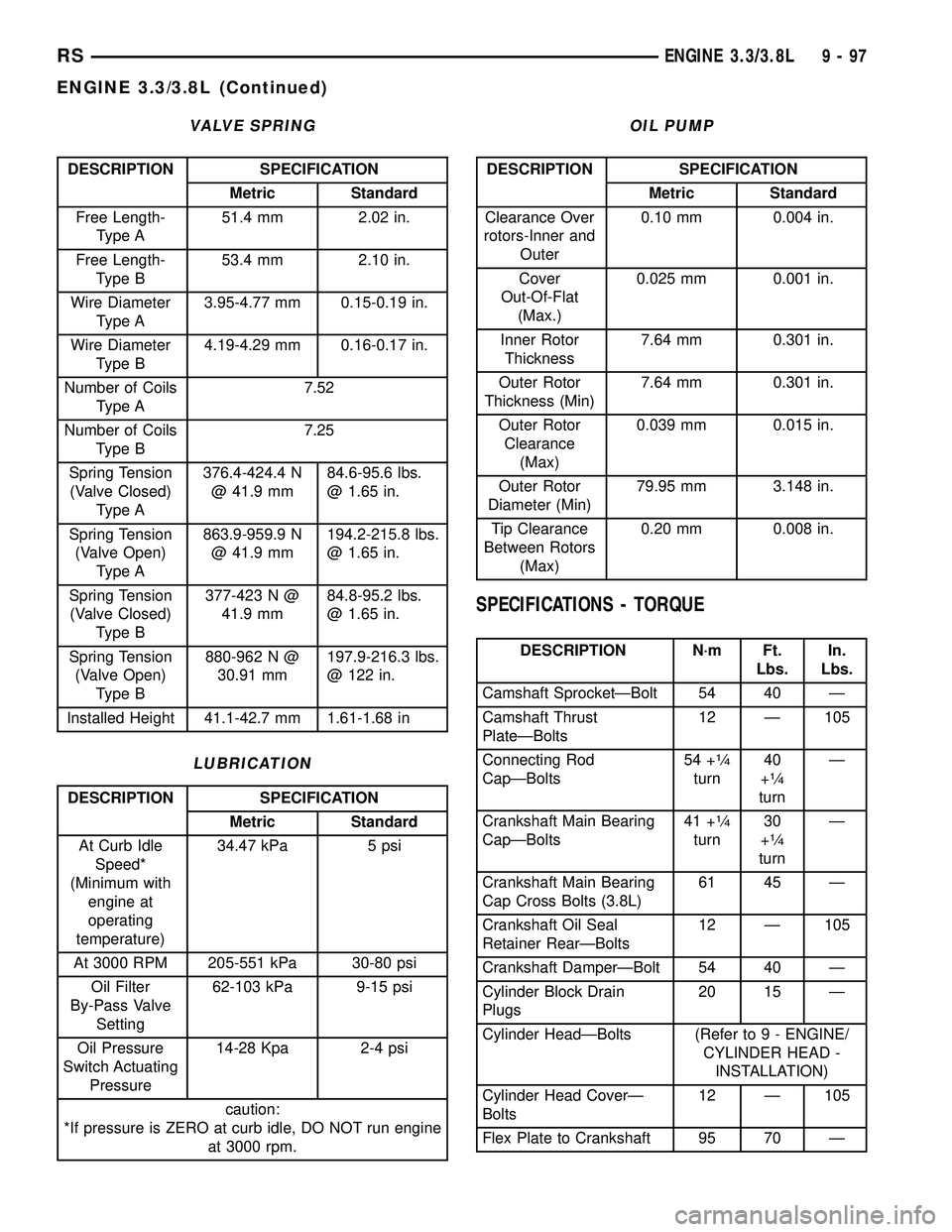
VALVE SPRING
DESCRIPTION SPECIFICATION
Metric Standard
Free Length-
Type A51.4 mm 2.02 in.
Free Length-
Type B53.4 mm 2.10 in.
Wire Diameter
Type A3.95-4.77 mm 0.15-0.19 in.
Wire Diameter
Type B4.19-4.29 mm 0.16-0.17 in.
Number of Coils
Type A7.52
Number of Coils
Type B7.25
Spring Tension
(Valve Closed)
Type A376.4-424.4 N
@ 41.9 mm84.6-95.6 lbs.
@ 1.65 in.
Spring Tension
(Valve Open)
Type A863.9-959.9 N
@ 41.9 mm194.2-215.8 lbs.
@ 1.65 in.
Spring Tension
(Valve Closed)
Type B377-423 N @
41.9 mm84.8-95.2 lbs.
@ 1.65 in.
Spring Tension
(Valve Open)
Type B880-962 N @
30.91 mm197.9-216.3 lbs.
@ 122 in.
Installed Height 41.1-42.7 mm 1.61-1.68 in
LUBRICATION
DESCRIPTION SPECIFICATION
Metric Standard
At Curb Idle
Speed*
(Minimum with
engine at
operating
temperature)34.47 kPa 5 psi
At 3000 RPM 205-551 kPa 30-80 psi
Oil Filter
By-Pass Valve
Setting62-103 kPa 9-15 psi
Oil Pressure
Switch Actuating
Pressure14-28 Kpa 2-4 psi
caution:
*If pressure is ZERO at curb idle, DO NOT run engine
at 3000 rpm.
OIL PUMP
DESCRIPTION SPECIFICATION
Metric Standard
Clearance Over
rotors-Inner and
Outer0.10 mm 0.004 in.
Cover
Out-Of-Flat
(Max.)0.025 mm 0.001 in.
Inner Rotor
Thickness7.64 mm 0.301 in.
Outer Rotor
Thickness (Min)7.64 mm 0.301 in.
Outer Rotor
Clearance
(Max)0.039 mm 0.015 in.
Outer Rotor
Diameter (Min)79.95 mm 3.148 in.
Tip Clearance
Between Rotors
(Max)0.20 mm 0.008 in.
SPECIFICATIONS - TORQUE
DESCRIPTION N´m Ft.
Lbs.In.
Lbs.
Camshaft SprocketÐBolt 54 40 Ð
Camshaft Thrust
PlateÐBolts12 Ð 105
Connecting Rod
CapÐBolts54 +
1¤4
turn40
+1¤4
turnÐ
Crankshaft Main Bearing
CapÐBolts41 +
1¤4
turn30
+1¤4
turnÐ
Crankshaft Main Bearing
Cap Cross Bolts (3.8L)61 45 Ð
Crankshaft Oil Seal
Retainer RearÐBolts12 Ð 105
Crankshaft DamperÐBolt 54 40 Ð
Cylinder Block Drain
Plugs20 15 Ð
Cylinder HeadÐBolts (Refer to 9 - ENGINE/
CYLINDER HEAD -
INSTALLATION)
Cylinder Head CoverÐ
Bolts12 Ð 105
Flex Plate to Crankshaft 95 70 Ð
RSENGINE 3.3/3.8L9-97
ENGINE 3.3/3.8L (Continued)
Page 1275 of 2339
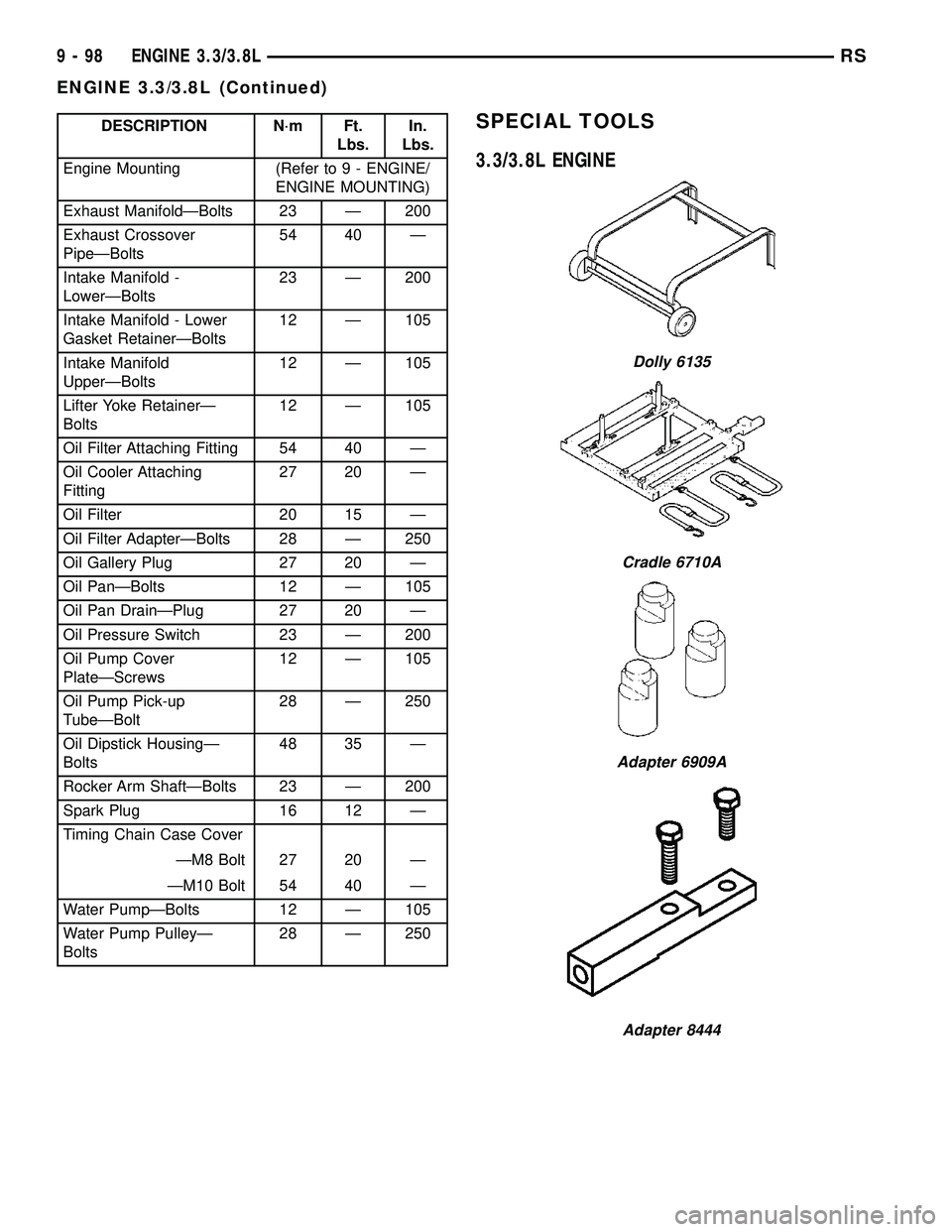
DESCRIPTION N´m Ft.
Lbs.In.
Lbs.
Engine Mounting (Refer to 9 - ENGINE/
ENGINE MOUNTING)
Exhaust ManifoldÐBolts 23 Ð 200
Exhaust Crossover
PipeÐBolts54 40 Ð
Intake Manifold -
LowerÐBolts23 Ð 200
Intake Manifold - Lower
Gasket RetainerÐBolts12 Ð 105
Intake Manifold
UpperÐBolts12 Ð 105
Lifter Yoke RetainerÐ
Bolts12 Ð 105
Oil Filter Attaching Fitting 54 40 Ð
Oil Cooler Attaching
Fitting27 20 Ð
Oil Filter 20 15 Ð
Oil Filter AdapterÐBolts 28 Ð 250
Oil Gallery Plug 27 20 Ð
Oil PanÐBolts 12 Ð 105
Oil Pan DrainÐPlug 27 20 Ð
Oil Pressure Switch 23 Ð 200
Oil Pump Cover
PlateÐScrews12 Ð 105
Oil Pump Pick-up
TubeÐBolt28 Ð 250
Oil Dipstick HousingÐ
Bolts48 35 Ð
Rocker Arm ShaftÐBolts 23 Ð 200
Spark Plug 16 12 Ð
Timing Chain Case Cover
ÐM8 Bolt 27 20 Ð
ÐM10 Bolt 54 40 Ð
Water PumpÐBolts 12 Ð 105
Water Pump PulleyÐ
Bolts28 Ð 250SPECIAL TOOLS
3.3/3.8L ENGINE
Dolly 6135
Cradle 6710A
Adapter 6909A
Adapter 8444
9 - 98 ENGINE 3.3/3.8LRS
ENGINE 3.3/3.8L (Continued)
Page 1305 of 2339
(6) Tighten number 1, 3 and 4 main cap bolts to 41
N´m + 1/4 Turn (30 ft. lbs.+ 1/4 Turn).
(7) Rotate the crankshaft until the number 6 pis-
ton is at TDC.
(8) To ensure correct thrust bearing alignment the
following procedure must be done:
a. Move crankshaft all the way to the rear of its
travel.
b. Then, move crankshaft all the way to the front
of its travel.
c. Wedge an appropriate tool between the rear of
the cylinder block and rear crankshaft counter-
weight. This will hold the crankshaft in it's most for-
ward position.
d. Tighten the #2 Thrust Bearing cap bolts to 41
N´m + 1/4 Turn (30 ft. lbs.+ 1/4 Turn). Remove the
holding tool.
(9) Install oil pan. (Refer to 9 - ENGINE/LUBRI-
CATION/OIL PAN - INSTALLATION)
(10) Fill engine crankcase with proper oil to cor-
rect level.
CRANKSHAFT
DESCRIPTION
DESCRIPTION - 3.3L
The nodular iron crankshaft is supported by four
main bearings, with number two position the thrust
bearing (Fig. 76). Crankshaft end sealing is provided
by front and rear rubber seals.
DESCRIPTION - 3.8L
The nodular iron crankshaft is supported by four
main bearings, with number two position providing
thrust bearing location (Fig. 77). Each main bearing
cap has two vertical retaining bolts. The two center
main caps have horizontal bolts to add increasedrigidity to the lower engine block (Fig. 77). Crank-
shaft end sealing is provided by front and rear rub-
ber seals.
STANDARD PROCEDURE - MEASURING
CRANKSHAFT END PLAY
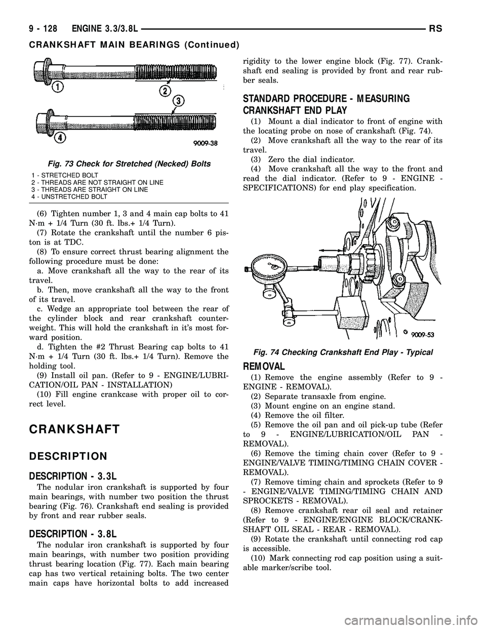
(1) Mount a dial indicator to front of engine with
the locating probe on nose of crankshaft (Fig. 74).
(2) Move crankshaft all the way to the rear of its
travel.
(3) Zero the dial indicator.
(4) Move crankshaft all the way to the front and
read the dial indicator. (Refer to 9 - ENGINE -
SPECIFICATIONS) for end play specification.
REMOVAL
(1) Remove the engine assembly (Refer to 9 -
ENGINE - REMOVAL).
(2) Separate transaxle from engine.
(3) Mount engine on an engine stand.
(4) Remove the oil filter.
(5) Remove the oil pan and oil pick-up tube (Refer
to 9 - ENGINE/LUBRICATION/OIL PAN -
REMOVAL).
(6) Remove the timing chain cover (Refer to 9 -
ENGINE/VALVE TIMING/TIMING CHAIN COVER -
REMOVAL).
(7) Remove timing chain and sprockets (Refer to 9
- ENGINE/VALVE TIMING/TIMING CHAIN AND
SPROCKETS - REMOVAL).
(8) Remove crankshaft rear oil seal and retainer
(Refer to 9 - ENGINE/ENGINE BLOCK/CRANK-
SHAFT OIL SEAL - REAR - REMOVAL).
(9) Rotate the crankshaft until connecting rod cap
is accessible.
(10) Mark connecting rod cap position using a suit-
able marker/scribe tool.
Fig. 73 Check for Stretched (Necked) Bolts
1 - STRETCHED BOLT
2 - THREADS ARE NOT STRAIGHT ON LINE
3 - THREADS ARE STRAIGHT ON LINE
4 - UNSTRETCHED BOLT
Fig. 74 Checking Crankshaft End Play - Typical
9 - 128 ENGINE 3.3/3.8LRS
CRANKSHAFT MAIN BEARINGS (Continued)
Page 1315 of 2339
RIGHT MOUNT
REMOVAL
(1) Remove air cleaner housing lid and clean air
hose from throttle body.
(2) Remove air cleaner element and housing.
(3) Disconnect make-up air hose from cylinder
head cover.
(4) Remove the load on the right engine mount by
carefully supporting the engine assembly with a floor
jack.
(5) Disconnect electrical harness support clips from
engine mount bracket.
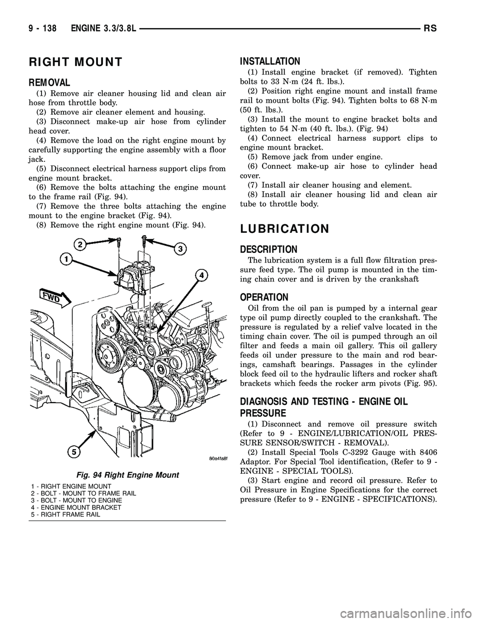
(6) Remove the bolts attaching the engine mount
to the frame rail (Fig. 94).
(7) Remove the three bolts attaching the engine
mount to the engine bracket (Fig. 94).
(8) Remove the right engine mount (Fig. 94).
INSTALLATION
(1) Install engine bracket (if removed). Tighten
bolts to 33 N´m (24 ft. lbs.).
(2) Position right engine mount and install frame
rail to mount bolts (Fig. 94). Tighten bolts to 68 N´m
(50 ft. lbs.).
(3) Install the mount to engine bracket bolts and
tighten to 54 N´m (40 ft. lbs.). (Fig. 94)
(4) Connect electrical harness support clips to
engine mount bracket.
(5) Remove jack from under engine.
(6) Connect make-up air hose to cylinder head
cover.
(7) Install air cleaner housing and element.
(8) Install air cleaner housing lid and clean air
tube to throttle body.
LUBRICATION
DESCRIPTION
The lubrication system is a full flow filtration pres-
sure feed type. The oil pump is mounted in the tim-
ing chain cover and is driven by the crankshaft
OPERATION
Oil from the oil pan is pumped by a internal gear
type oil pump directly coupled to the crankshaft. The
pressure is regulated by a relief valve located in the
timing chain cover. The oil is pumped through an oil
filter and feeds a main oil gallery. This oil gallery
feeds oil under pressure to the main and rod bear-
ings, camshaft bearings. Passages in the cylinder
block feed oil to the hydraulic lifters and rocker shaft
brackets which feeds the rocker arm pivots (Fig. 95).
DIAGNOSIS AND TESTING - ENGINE OIL
PRESSURE
(1) Disconnect and remove oil pressure switch
(Refer to 9 - ENGINE/LUBRICATION/OIL PRES-
SURE SENSOR/SWITCH - REMOVAL).
(2) Install Special Tools C-3292 Gauge with 8406
Adaptor. For Special Tool identification, (Refer to 9 -
ENGINE - SPECIAL TOOLS).
(3) Start engine and record oil pressure. Refer to
Oil Pressure in Engine Specifications for the correct
pressure (Refer to 9 - ENGINE - SPECIFICATIONS).
Fig. 94 Right Engine Mount
1 - RIGHT ENGINE MOUNT
2 - BOLT - MOUNT TO FRAME RAIL
3 - BOLT - MOUNT TO ENGINE
4 - ENGINE MOUNT BRACKET
5 - RIGHT FRAME RAIL
9 - 138 ENGINE 3.3/3.8LRS
Page 1316 of 2339

OIL
STANDARD PROCEDURE
STANDARD PROCEDURE - ENGINE OIL AND
FILTER CHANGE
Change engine oil at mileage and time intervals
described in the Maintenance Schedule. (Refer to
LUBRICATION & MAINTENANCE/MAINTE-
NANCE SCHEDULES - DESCRIPTION)
WARNING: NEW OR USED ENGINE OIL CAN BE
IRRITATING TO THE SKIN. AVOID PROLONGED OR
REPEATED SKIN CONTACT WITH ENGINE OIL.
CONTAMINANTS IN USED ENGINE OIL, CAUSED BY
INTERNAL COMBUSTION, CAN BE HAZARDOUS TO
YOUR HEALTH. THOROUGHLY WASH EXPOSED
SKIN WITH SOAP AND WATER. DO NOT WASH
SKIN WITH GASOLINE, DIESEL FUEL, THINNER, OR
SOLVENTS, HEALTH PROBLEMS CAN RESULT. DO
NOT POLLUTE, DISPOSE OF USED ENGINE OIL
PROPERLY. CONTACT YOUR DEALER OR GOVERN-
MENT AGENCY FOR LOCATION OF COLLECTION
CENTER IN YOUR AREA.Run engine until achieving normal operating tem-
perature.
(1) Position the vehicle on a level surface and turn
engine off.
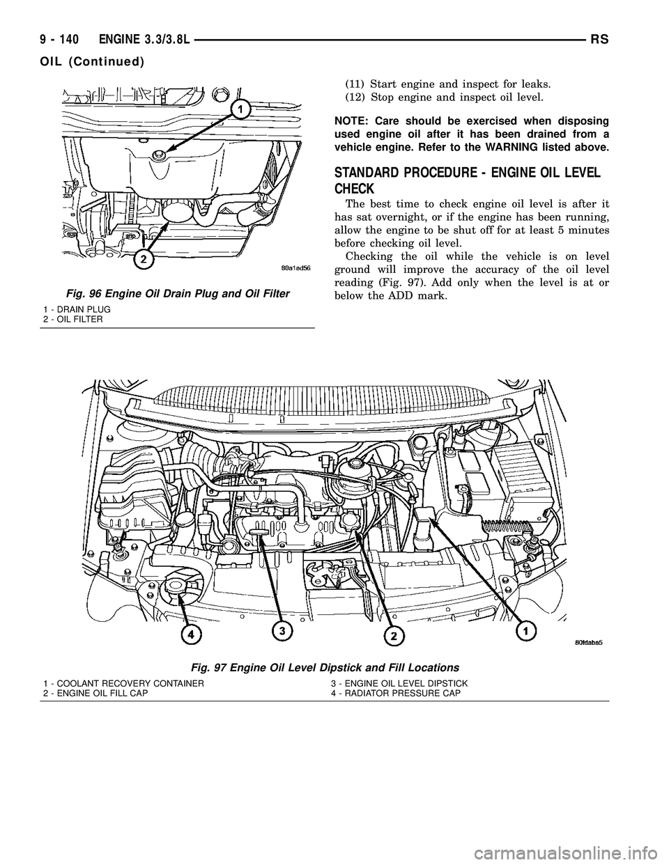
(2) Open hood, remove oil fill cap (Fig. 97).
(3) Hoist and support vehicle on safety stands.
Refer to Hoisting and Jacking Recommendations.
(Refer to LUBRICATION & MAINTENANCE/HOIST-
ING - STANDARD PROCEDURE)
(4) Place a suitable drain pan under crankcase
drain (Fig. 96).
(5) Remove drain plug from crankcase (Fig. 96)
and allow oil to drain into pan. Inspect drain plug
threads for stretching or other damage. Replace
drain plug and gasket if damaged.
(6) Remove oil filter. (Refer to 9 - ENGINE/LUBRI-
CATION/OIL FILTER - REMOVAL)
(7) Install and tighten drain plug in crankcase.
(8) Install new oil filter. (Refer to 9 - ENGINE/LU-
BRICATION/OIL FILTER - INSTALLATION)
(9) Lower vehicle and fill crankcase with specified
type and amount of engine oil. (Refer to LUBRICA-
TION & MAINTENANCE/FLUID TYPES -
DESCRIPTION)
(10) Install oil fill cap.
Fig. 95 Engine Oiling System
1 - OIL SUPPLY FOR BALL SOCKET THROUGH PUSH ROD 7 - OUTER ROTOR
2 - OIL SUPPLY PASSAGE FROM SHAFT TO ROCKER ARM 8 - INNER ROTOR
3 - ROCKER SHAFT 9 - RELIEF VALVE
4 - OIL FLOWS TO ONLY ONE PEDASTAL ON EACH HEAD; THIRD
FROM REAR ON RIGHT HEAD, THIRD FROM FRONT ON LEFT
HEAD10 - OIL PAN
5 - ROCKER SHAFT TOWER 11 - OIL SCREEN
6 - CRANKSHAFT 12 - OIL PUMP CASE
RSENGINE 3.3/3.8L9 - 139
LUBRICATION (Continued)
Page 1317 of 2339
(11) Start engine and inspect for leaks.
(12) Stop engine and inspect oil level.
NOTE: Care should be exercised when disposing
used engine oil after it has been drained from a
vehicle engine. Refer to the WARNING listed above.
STANDARD PROCEDURE - ENGINE OIL LEVEL
CHECK
The best time to check engine oil level is after it
has sat overnight, or if the engine has been running,
allow the engine to be shut off for at least 5 minutes
before checking oil level.
Checking the oil while the vehicle is on level
ground will improve the accuracy of the oil level
reading (Fig. 97). Add only when the level is at or
below the ADD mark.
Fig. 97 Engine Oil Level Dipstick and Fill Locations
1 - COOLANT RECOVERY CONTAINER 3 - ENGINE OIL LEVEL DIPSTICK
2 - ENGINE OIL FILL CAP 4 - RADIATOR PRESSURE CAP
Fig. 96 Engine Oil Drain Plug and Oil Filter
1 - DRAIN PLUG
2 - OIL FILTER
9 - 140 ENGINE 3.3/3.8LRS
OIL (Continued)