2005 CHRYSLER CARAVAN height
[x] Cancel search: heightPage 488 of 2339

RESTRAINTS
TABLE OF CONTENTS
page page
RESTRAINTS
DESCRIPTION..........................2
OPERATION............................4
WARNING
WARNINGS...........................5
DIAGNOSIS AND TESTING - AIRBAG SYSTEM . 6
STANDARD PROCEDURE
STANDARD PROCEDURE - HANDLING
AIRBAGS.............................6
STANDARD PROCEDURE - SERVICE
AFTER AN AIRBAG DEPLOYMENT.........7
BELT TENSION SENSOR
DESCRIPTION..........................8
OPERATION............................9
CHILD RESTRAINT ANCHOR
DESCRIPTION..........................9
OPERATION...........................10
CLOCKSPRING
DESCRIPTION.........................10
OPERATION...........................11
STANDARD PROCEDURE - CLOCKSPRING
CENTERING.........................11
REMOVAL.............................12
INSTALLATION.........................12
CURTAIN AIRBAG
DESCRIPTION.........................12
OPERATION...........................13
REMOVAL.............................14
INSTALLATION.........................16
DRIVER AIRBAG
DESCRIPTION.........................16
OPERATION...........................16
REMOVAL.............................17
INSTALLATION.........................18
IMPACT SENSOR
DESCRIPTION.........................18
REMOVAL.............................19
INSTALLATION.........................21
KNEE BLOCKER AIRBAG
DESCRIPTION.........................22
OPERATION...........................22
REMOVAL.............................23
INSTALLATION.........................23
OCCUPANT CLASSIFICATION MODULE
DESCRIPTION.........................25
OPERATION...........................25
REMOVAL.............................26
INSTALLATION.........................26OCCUPANT RESTRAINT CONTROLLER
DESCRIPTION.........................27
OPERATION...........................28
REMOVAL.............................29
INSTALLATION.........................29
PASSENGER AIRBAG
DESCRIPTION.........................30
OPERATION...........................30
REMOVAL.............................30
INSTALLATION.........................32
PASSENGER AIRBAG DISABLED INDICATOR
DESCRIPTION.........................33
OPERATION...........................33
REMOVAL.............................34
INSTALLATION.........................34
SEAT BELT BUCKLE - FRONT INBOARD
REMOVAL.............................35
INSTALLATION.........................35
SEAT BELT BUCKLE - FIRST ROW INBOARD -
QUAD BUCKET
REMOVAL.............................35
INSTALLATION.........................36
SEAT BELT BUCKLE - FIRST ROW - BENCH
REMOVAL.............................36
INSTALLATION.........................37
SEAT BELT BUCKLE - SECOND ROW
INBOARD - 50/50 BENCH
REMOVAL.............................37
INSTALLATION.........................38
SEAT BELT HEIGHT ADJUSTER-BOR
C-PILLAR
REMOVAL.............................38
INSTALLATION.........................38
SEAT BELT HEIGHT ADJUSTER KNOB
REMOVAL.............................38
INSTALLATION.........................38
SEAT BELT & RETRACTOR - OUTBOARD -
FRONT
REMOVAL.............................38
INSTALLATION.........................39
SEAT BELT & RETRACTOR - FIRST ROW -
OUTBOARD
REMOVAL.............................39
INSTALLATION.........................40
SEAT BELT BUCKLE - SECOND ROW - THREE
PASSENGER BENCH
REMOVAL.............................40
INSTALLATION.........................40
RSRESTRAINTS8O-1
Page 489 of 2339

SEAT BELT & RETRACTOR - SECOND ROW -
RIGHT OUTBOARD
REMOVAL.............................40
INSTALLATION.........................40
SEAT BELT & RETRACTOR - SECOND ROW -
RIGHT OUTBOARD WITH REAR HVAC - LWB
REMOVAL.............................41
INSTALLATION.........................41
SEAT BELT & RETRACTOR - SECOND ROW -
LEFT OUTBOARD
REMOVAL.............................42INSTALLATION.........................42
SEAT BELT TENSIONER
DESCRIPTION.........................43
OPERATION...........................43
SEAT WEIGHT BLADDER & PRESSURE
SENSOR
DESCRIPTION.........................43
OPERATION...........................44
RESTRAINTS
DESCRIPTION
This vehicle is equipped with a Frontal Impact Air-
bag System, which utilizes the driver/passenger air-
bags, two front impact sensors, and seat belt
tensioners located in the front seat belt buckles. This
system is designed to protect occupants in the event
of a front impact collision. These airbags are all ser-
viceable parts. The tensioners are integral to the
front seat belt buckles. If these pyrotechnics are
deployed or defective, they must be replaced.
Vehicles equipped with the Side Impact Airbag
System utilize a curtain airbag, three side impact
sensors, and the Occupant Restraint Controller
(ORC) to determine if the airbag should be deployed.
Following a side impact event where the side airbag
was deployed, the headliner as well as the curtain
airbag must be replaced.
The occupant restraints include both active and
passive types. Active restraints are those which
require the vehicle occupants to take some action to
employ, such as fastening a seat belt; while passive
restraints require no action by the vehicle occupants
to be employed.
ACTIVE RESTRAINTS
The active restraints include:
²Front Seat Belts- Both front seating positions
are equipped with three-point seat belt systems
employing a lower B-pillar mounted inertia latch-
type retractor, height-adjustable upper B-pillar
mounted turning loops, a fixed lower seat belt anchor
secured to the lower B-pillar, and a traveling end-re-
lease buckle secured to the inboard side of the seat
cushion frame. The driver side front seat belt buckle
includes an integral Hall-effect seat belt switch that
detects whether the driver side front seat belt has
been fastened.²Rear Seat Belts- Both outboard rear second
and third seating positions are equipped with three-
point seat belt systems. The outboard seating posi-
tion belts employ a lower C or D-pillar mounted
inertia latch-type retractor, a fixed position upper C
or D-pillar mounted turning loop, and a fixed lower
seat belt anchor secured to the inboard side of the
seat cushion frame.
²Child Restraint Anchors- Also equipped in
this vehicle are two, fixed-position, child seat upper
tether anchors located on the lower seat cushion, in
the rear of the lower seat cushion. There is one
anchor integral to the back of the third row seat back
panel, one on each seat back panel. Two lower second
row anchors are also provided for each rear outboard
seating position. The lower anchors are integral to
the seat cushion frame and are accessed from the
front of the second row seat where the seat back
meets the seat cushion.
PASSIVE RESTRAINTS
The passive restraints available for this model
include the following:
²Dual Front Airbags- Multistage driver. front
passenger, and driver knee blocker airbags are avail-
able for this model. This airbag system is a passive,
inflatable, Supplemental Restraint System (SRS) and
vehicles with this equipment can be readily identified
by the ªSRS - AIRBAGº logo molded into the driver
airbag trim cover in the center of the steering wheel
and also into the passenger airbag door on the
instrument panel above the glove box. Vehicles with
the airbag system can also be identified by the airbag
indicator, which will illuminate in the instrument
cluster for about seven seconds as a bulb test each
time the ignition switch is turned to the ON position.
A pyrotechnic-type seat belt tensioner is integral to
the driver and passenger front seat belt buckle of all
models equipped with dual front airbags.
8O - 2 RESTRAINTSRS
Page 525 of 2339

INSTALLATION
(1) Push belt through seat cushion.
(2) While looking at the bottom of the seat, locate
retaining bolt hole on the left side of the seat riser.
Install retaining bolt into seat riser (Fig. 45). Torque
anchor bolt to 39 N´m (29 ft. lbs.).
(3) Place seat into track and on front anchors.
(4) Pull #3 strap and install seat onto latching
area.
(5) Pull seat assembly down firmly and snap into
track.
(6) Pull handle #1 and fold seat back rearward.
(7) Close rear liftgate.
SEAT BELT HEIGHT
ADJUSTER-BORC-PILLAR
REMOVAL
(1) Remove turning loop retaining bolt.
(2) Remove B or C-pillar trim cover.
(3) Remove two screws attaching shoulder belt
height adjuster to pillar.
(4) Remove height adjuster from vehicle.
INSTALLATION
(1) Place height adjuster into position.
(2) Install screws attaching shoulder belt height
adjuster to pillar.
(3) Install B or C-pillar trim cover.
(4) Install turning loop to height adjuster. Torque
anchor bolt to 39 N´m (29 ft. lbs.).
SEAT BELT HEIGHT
ADJUSTER KNOB
REMOVAL
(1) Disengage clips attaching clam shell cover to
seat belt turning loop and open cover.
(2) Using a trim tool (special tool #C-4755), gently
pry knob from seat belt height adjuster.
INSTALLATION
(1) Place seat belt height adjuster knob in position
on height adjuster.
(2) Firmly push knob on until retainers engage.
(3) Reinstall turning loop clam shell cover.
(4) Verify seat belt operation. Make sure it moves
through loop without binding.
SEAT BELT & RETRACTOR -
OUTBOARD - FRONT
REMOVAL
(1) Open door.
(2) Move seat all the way forward.
(3) Open hood.
(4) Disconnect and isolate the battery negative
cable.
(5)
WARNING: Wait two minutes for the airbag system
reserve capacitor to discharge before beginning
any airbag system or component service. Failure to
do so may result in accidental airbag deployment,
personal injury or death.
(6) Remove shoulder harness height adjuster knob
by pulling it straight away from adjuster (Fig. 48).
(7) Remove cover from seat belt turning loop (Fig.
48).
(8) Remove bolt attaching turning loop to shoulder
belt height adjuster (Fig. 48).
(9) Remove upper B-pillar trim cover (Fig. 48).
NOTE: If equipped with the Occupant Classification
System (OCS), there is a Belt Tension Sensor
located on the lower seat belt anchor on the pas-
senger front seat belt.
Fig. 48 SEAT BELT - OUTBOARD FRONT
1 - B-PILLAR TRIM LOWER
2 - BELT
3 - B-PILLAR TRIM UPPER
4 - HEIGHT ADJUSTER
5 - KNOB
6 - B-PILLAR TRIM LOWER
7 - FLOOR ANCHOR
8 - FLOOR ANCHOR
9 - 30É OUTBOARD
10 - RETRACTOR
8O - 38 RESTRAINTSRS
SEAT BELT BUCKLE - SECOND ROW INBOARD - 50/50 BENCH (Continued)
Page 526 of 2339

(10) Remove the lower seat belt anchor bolt (Fig.
49).
(11) Disconnect the electrical connector if equipped
with OCS (Fig. 49).
(12) Remove front door sill plate (Fig. 48).
(13) Remove sliding door sill plate (Fig. 48).
(14) Remove lower B-pillar trim cover (Fig. 48).
(15) Disconnect the seat belt retractor electrical
connector (Fig. 48).
(16) Remove seat belt retractor attaching bolt (Fig.
48).
(17) Remove the seat belt and retractor from vehi-
cle.
INSTALLATION
WARNING: Inspect the condition of the shoulder
belt and lap belt. Replace any belt that is cut,
frayed, torn, or damaged in any way. Also, replace
the shoulder belt if the retractor is either damaged
or inoperative.
(1) Place seat belt and retractor into position (Fig.
48).
(2) Install bolt attaching seat belt retractor to
B-pillar (Fig. 48). Torque bolt to 39 N´m (29 ft. lbs.).
(3) Connect the seat belt retractor electrical con-
nector (Fig. 48).
(4) Install the lower B-pillar trim cover (Fig. 48).
(5) Install the sliding door sill plate (Fig. 48).
(6) Install the front door sill plate (Fig. 48).(7) Install the lower seat belt anchor bolt (Fig. 49).
Torque bolt to 39 N´m (29 ft. lbs.).
NOTE: If equipped with the Occupant Classification
System (OCS), there is a Belt Tension Sensor
located on the lower seat belt anchor on the pas-
senger front seat belt.
(8) Connect the belt tension sensor connector (if
equipped with OCS) (Fig. 49).
(9) Install the upper B-pillar trim cover (Fig. 48).
(10) Install the bolt attaching turning loop to
shoulder belt height adjuster (Fig. 48). Torque bolt to
39 N´m (29 ft. lbs.).
(11) Install the cover to the seat belt turning loop
(Fig. 48).
(12) Install the shoulder harness height adjuster
knob by pushing it straight onto the adjuster (Fig.
48).
(13) Move seat back to approximate customer posi-
tion.
WARNING: If equipped with the OCS, do not con-
nect the battery negative cable (Refer to 8 - ELEC-
TRICAL/RESTRAINTS - DIAGNOSIS AND TESTING -
AIRBAG SYSTEM). Personal injury or death may
result if the system test is not performed first.
WARNING: If equipped with the OCS, following suc-
cessful completion of the Airbag System test proce-
dure, the Occupant Classification System
Verification Test must be done using a scan tool
and the appropriate diagnostic information.
(14) Verify vehicle and system operation.
(15) Close hood.
SEAT BELT & RETRACTOR -
FIRST ROW - OUTBOARD
REMOVAL
(1) Remove first and second row seats.
(2) Remove first row seat belt lower anchor bolt.
(3) Remove first row seat belt upper turning loop
anchor bolt.
(4) Remove liftgate sill plate.
(5) Remove upper liftgate trim.
(6) Remove second seat lower anchor bolt.
(7) Remove second seat upper turning loop anchor
bolt.
(8) Remove D-pillar trim cover.
(9) Disconnect speaker connector. The left side has
the speaker mounted in the D-pillar trim cover and
the right side will have the speaker mounted in the
rear of the quarter trim panel, but the connector is
Fig. 49 BELT TENSION SENSOR/LOWER SEAT
BELT ANCHOR
1 - A-PILLAR
2 - SEAT BELT ANCHOR/BELT TENSION SENSOR
3 - BELT TENSION SENSOR CONNECTOR
RSRESTRAINTS8O-39
SEAT BELT & RETRACTOR - OUTBOARD - FRONT (Continued)
Page 1196 of 2339

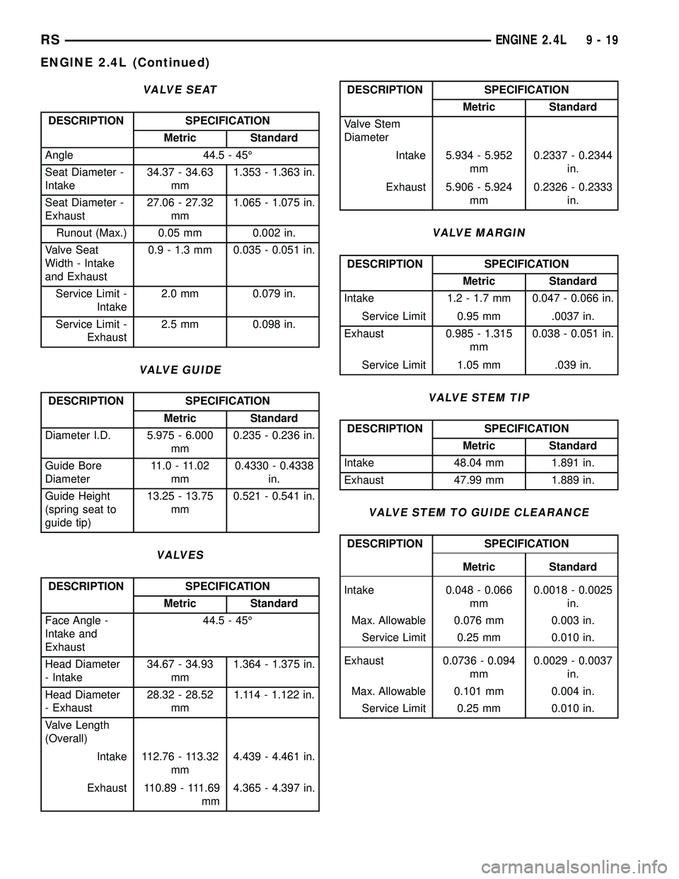
VALVE SEAT
DESCRIPTION SPECIFICATION
Metric Standard
Angle 44.5 - 45É
Seat Diameter -
Intake34.37 - 34.63
mm1.353 - 1.363 in.
Seat Diameter -
Exhaust27.06 - 27.32
mm1.065 - 1.075 in.
Runout (Max.) 0.05 mm 0.002 in.
Valve Seat
Width - Intake
and Exhaust0.9 - 1.3 mm 0.035 - 0.051 in.
Service Limit -
Intake2.0 mm 0.079 in.
Service Limit -
Exhaust2.5 mm 0.098 in.
VALVE GUIDE
DESCRIPTION SPECIFICATION
Metric Standard
Diameter I.D. 5.975 - 6.000
mm0.235 - 0.236 in.
Guide Bore
Diameter11.0 - 11.02
mm0.4330 - 0.4338
in.
Guide Height
(spring seat to
guide tip)13.25 - 13.75
mm0.521 - 0.541 in.
VALVES
DESCRIPTION SPECIFICATION
Metric Standard
Face Angle -
Intake and
Exhaust44.5 - 45É
Head Diameter
- Intake34.67 - 34.93
mm1.364 - 1.375 in.
Head Diameter
- Exhaust28.32 - 28.52
mm1.114 - 1.122 in.
Valve Length
(Overall)
Intake 112.76 - 113.32
mm4.439 - 4.461 in.
Exhaust 110.89 - 111.69
mm4.365 - 4.397 in.
DESCRIPTION SPECIFICATION
Metric Standard
Valve Stem
Diameter
Intake 5.934 - 5.952
mm0.2337 - 0.2344
in.
Exhaust 5.906 - 5.924
mm0.2326 - 0.2333
in.
VALVE MARGIN
DESCRIPTION SPECIFICATION
Metric Standard
Intake 1.2 - 1.7 mm 0.047 - 0.066 in.
Service Limit 0.95 mm .0037 in.
Exhaust 0.985 - 1.315
mm0.038 - 0.051 in.
Service Limit 1.05 mm .039 in.
VALVE STEM TIP
DESCRIPTION SPECIFICATION
Metric Standard
Intake 48.04 mm 1.891 in.
Exhaust 47.99 mm 1.889 in.
VALVE STEM TO GUIDE CLEARANCE
DESCRIPTION SPECIFICATION
Metric Standard
Intake 0.048 - 0.066
mm0.0018 - 0.0025
in.
Max. Allowable 0.076 mm 0.003 in.
Service Limit 0.25 mm 0.010 in.
Exhaust 0.0736 - 0.094
mm0.0029 - 0.0037
in.
Max. Allowable 0.101 mm 0.004 in.
Service Limit 0.25 mm 0.010 in.
RSENGINE 2.4L9-19
ENGINE 2.4L (Continued)
Page 1197 of 2339

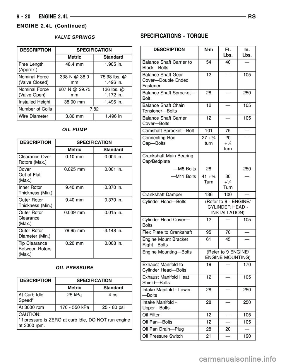
VALVE SPRINGS
DESCRIPTION SPECIFICATION
Metric Standard
Free Length
(Approx.)48.4 mm 1.905 in.
Nominal Force
(Valve Closed)338 N @ 38.0
mm75.98 lbs. @
1.496 in.
Nominal Force
(Valve Open)607 N @ 29.75
mm136 lbs. @
1.172 in.
Installed Height 38.00 mm 1.496 in.
Number of Coils 7.82
Wire Diameter 3.86 mm 1.496 in
OIL PUMP
DESCRIPTION SPECIFICATION
Metric Standard
Clearance Over
Rotors (Max.)0.10 mm 0.004 in.
Cover
Out-of-Flat
(Max.)0.025 mm 0.001 in.
Inner Rotor
Thickness (Min.)9.40 mm 0.370 in.
Outer Rotor
Thickness (Min.)9.40 mm 0.370 in.
Outer Rotor
Clearance
(Max.)0.039 mm 0.015 in.
Outer Rotor
Diameter (Min.)79.95 mm 3.148 in.
Tip Clearance
Between Rotors
(Max.)0.20 mm 0.008 in.
OIL PRESSURE
DESCRIPTION SPECIFICATION
Metric Standard
At Curb Idle
Speed*25 kPa 4 psi
At 3000 rpm 170 - 550 kPa 25 - 80 psi
CAUTION:
*If pressure is ZERO at curb idle, DO NOT run engine
at 3000 rpm.
SPECIFICATIONS - TORQUE
DESCRIPTION N´m Ft.
Lbs.In.
Lbs.
Balance Shaft Carrier to
BlockÐBolts54 40 Ð
Balance Shaft Gear
CoverÐDouble Ended
Fastener12 Ð 105
Balance Shaft SprocketÐ
Bolt28 Ð 250
Balance Shaft Chain
TensionerÐBolts12 Ð 105
Balance Shaft Carrier
CoverÐBolts12 Ð 105
Camshaft SprocketÐBolt 101 75 Ð
Connecting Rod
CapÐBolts27 +
1¤4
turn20
+1¤4
turnÐ
Crankshaft Main Bearing
Cap/Bedplate
ÐM8 Bolts 28 250
ÐM11 Bolts 41 +
1¤4
Turn30
+1¤4
TurnÐ
Crankshaft Damper 136 100 Ð
Cylinder HeadÐBolts (Refer to 9 - ENGINE/
CYLINDER HEAD -
INSTALLATION)
Cylinder Head CoverÐ
Bolts12 Ð 105
Flex Plate to Crankshaft 95 70 Ð
Engine Mount Bracket
RightÐBolts61 45 Ð
Engine MountingÐBolts (Refer to 9 ENGINE/
ENGINE MOUNTING)
Exhaust Manifold to
Cylinder HeadÐBolts19 Ð 170
Exhaust Manifold Heat
ShieldÐBolts12 Ð 105
Intake Manifold - Lower
ÐBolts28 Ð 250
Intake Manifold -
UpperÐBolts28 Ð 250
Oil Filter 12 Ð 105
Oil PanÐBolts 12 Ð 105
Oil Pan DrainÐPlug 28 20 Ð
Oil Pressure Switch 21 Ð 190
9 - 20 ENGINE 2.4LRS
ENGINE 2.4L (Continued)
Page 1204 of 2339

INSPECTION
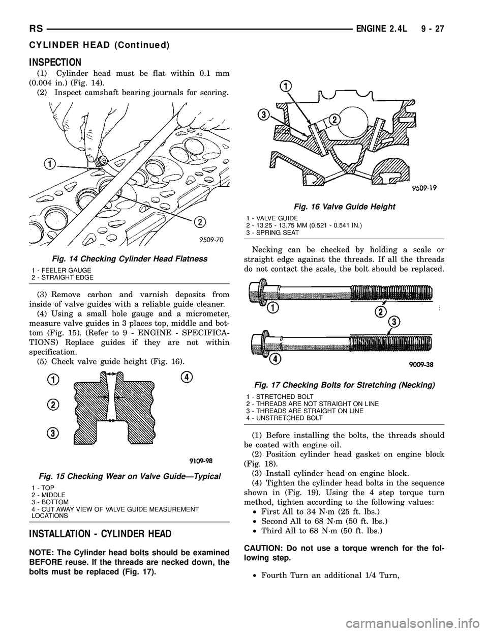
(1) Cylinder head must be flat within 0.1 mm
(0.004 in.) (Fig. 14).
(2) Inspect camshaft bearing journals for scoring.
(3) Remove carbon and varnish deposits from
inside of valve guides with a reliable guide cleaner.
(4) Using a small hole gauge and a micrometer,
measure valve guides in 3 places top, middle and bot-
tom (Fig. 15). (Refer to 9 - ENGINE - SPECIFICA-
TIONS) Replace guides if they are not within
specification.
(5) Check valve guide height (Fig. 16).
INSTALLATION - CYLINDER HEAD
NOTE: The Cylinder head bolts should be examined
BEFORE reuse. If the threads are necked down, the
bolts must be replaced (Fig. 17).Necking can be checked by holding a scale or
straight edge against the threads. If all the threads
do not contact the scale, the bolt should be replaced.
(1) Before installing the bolts, the threads should
be coated with engine oil.
(2) Position cylinder head gasket on engine block
(Fig. 18).
(3) Install cylinder head on engine block.
(4) Tighten the cylinder head bolts in the sequence
shown in (Fig. 19). Using the 4 step torque turn
method, tighten according to the following values:
²First All to 34 N´m (25 ft. lbs.)
²Second All to 68 N´m (50 ft. lbs.)
²Third All to 68 N´m (50 ft. lbs.)
CAUTION: Do not use a torque wrench for the fol-
lowing step.
²Fourth Turn an additional 1/4 Turn,
Fig. 14 Checking Cylinder Head Flatness
1 - FEELER GAUGE
2 - STRAIGHT EDGE
Fig. 15 Checking Wear on Valve GuideÐTypical
1-TOP
2 - MIDDLE
3 - BOTTOM
4 - CUT AWAY VIEW OF VALVE GUIDE MEASUREMENT
LOCATIONS
Fig. 16 Valve Guide Height
1 - VALVE GUIDE
2 - 13.25 - 13.75 MM (0.521 - 0.541 IN.)
3 - SPRING SEAT
Fig. 17 Checking Bolts for Stretching (Necking)
1 - STRETCHED BOLT
2 - THREADS ARE NOT STRAIGHT ON LINE
3 - THREADS ARE STRAIGHT ON LINE
4 - UNSTRETCHED BOLT
RSENGINE 2.4L9-27
CYLINDER HEAD (Continued)
Page 1211 of 2339

CAUTION: When oversize valves are used, the cor-
responding oversize valve seal must also be used.
Excessive guide wear may result if oversize seals
are not used with oversize valves.
(3) Install valve springs and retainers. Compress
valve springs only enough to install locks, taking
care not to misalign the direction of compression.
Nicked valve stems may result from misalignment of
the valve spring compressor.
CAUTION: When depressing the valve spring retain-
ers with valve spring compressor the locks can
become dislocated. Ensure both locks are in the
correct location after removing tool.
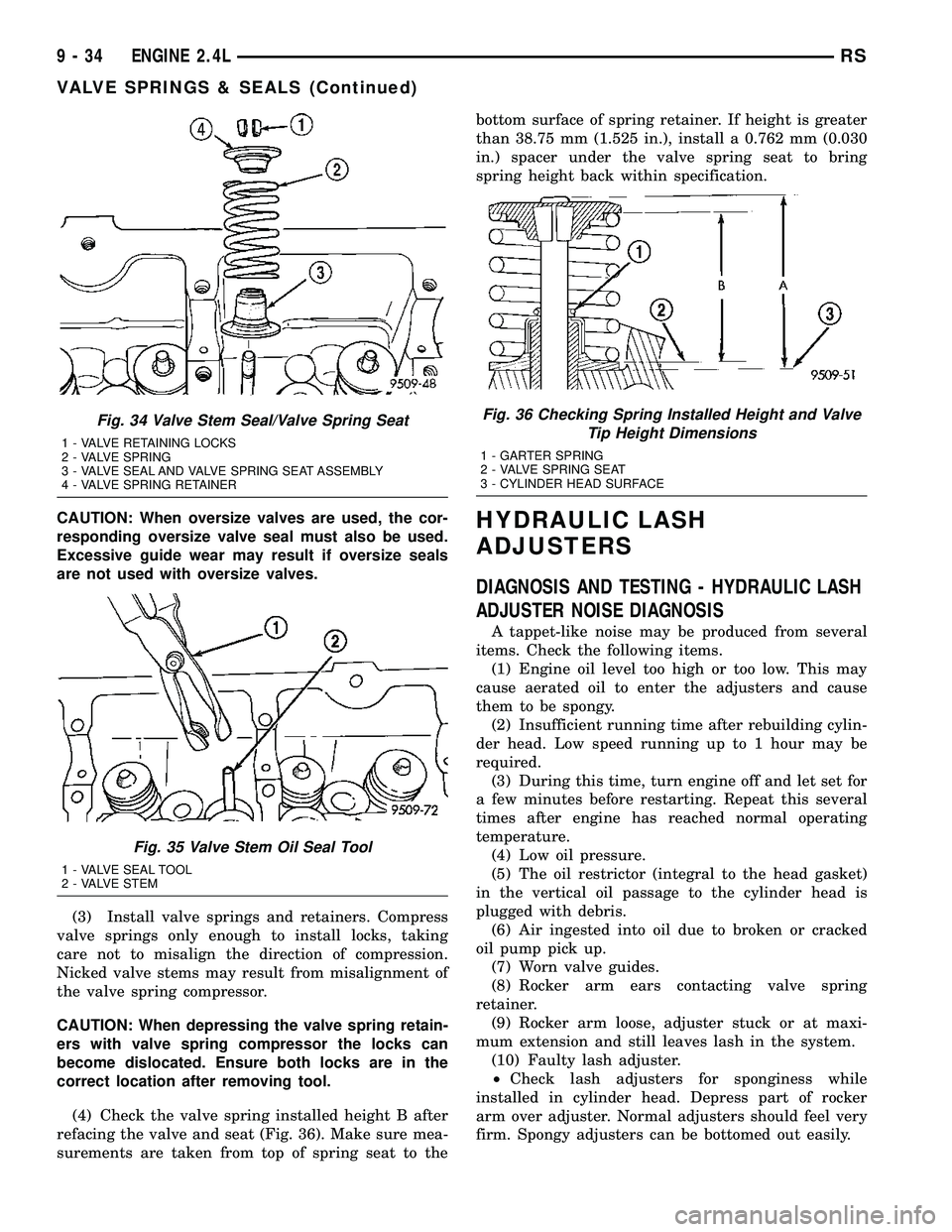
(4) Check the valve spring installed height B after
refacing the valve and seat (Fig. 36). Make sure mea-
surements are taken from top of spring seat to thebottom surface of spring retainer. If height is greater
than 38.75 mm (1.525 in.), install a 0.762 mm (0.030
in.) spacer under the valve spring seat to bring
spring height back within specification.HYDRAULIC LASH
ADJUSTERS
DIAGNOSIS AND TESTING - HYDRAULIC LASH
ADJUSTER NOISE DIAGNOSIS
A tappet-like noise may be produced from several
items. Check the following items.
(1) Engine oil level too high or too low. This may
cause aerated oil to enter the adjusters and cause
them to be spongy.
(2) Insufficient running time after rebuilding cylin-
der head. Low speed running up to 1 hour may be
required.
(3) During this time, turn engine off and let set for
a few minutes before restarting. Repeat this several
times after engine has reached normal operating
temperature.
(4) Low oil pressure.
(5) The oil restrictor (integral to the head gasket)
in the vertical oil passage to the cylinder head is
plugged with debris.
(6) Air ingested into oil due to broken or cracked
oil pump pick up.
(7) Worn valve guides.
(8) Rocker arm ears contacting valve spring
retainer.
(9) Rocker arm loose, adjuster stuck or at maxi-
mum extension and still leaves lash in the system.
(10) Faulty lash adjuster.
²Check lash adjusters for sponginess while
installed in cylinder head. Depress part of rocker
arm over adjuster. Normal adjusters should feel very
firm. Spongy adjusters can be bottomed out easily.
Fig. 34 Valve Stem Seal/Valve Spring Seat
1 - VALVE RETAINING LOCKS
2 - VALVE SPRING
3 - VALVE SEAL AND VALVE SPRING SEAT ASSEMBLY
4 - VALVE SPRING RETAINER
Fig. 35 Valve Stem Oil Seal Tool
1 - VALVE SEAL TOOL
2 - VALVE STEM
Fig. 36 Checking Spring Installed Height and Valve
Tip Height Dimensions
1 - GARTER SPRING
2 - VALVE SPRING SEAT
3 - CYLINDER HEAD SURFACE
9 - 34 ENGINE 2.4LRS
VALVE SPRINGS & SEALS (Continued)