2005 CHRYSLER CARAVAN height
[x] Cancel search: heightPage 1273 of 2339
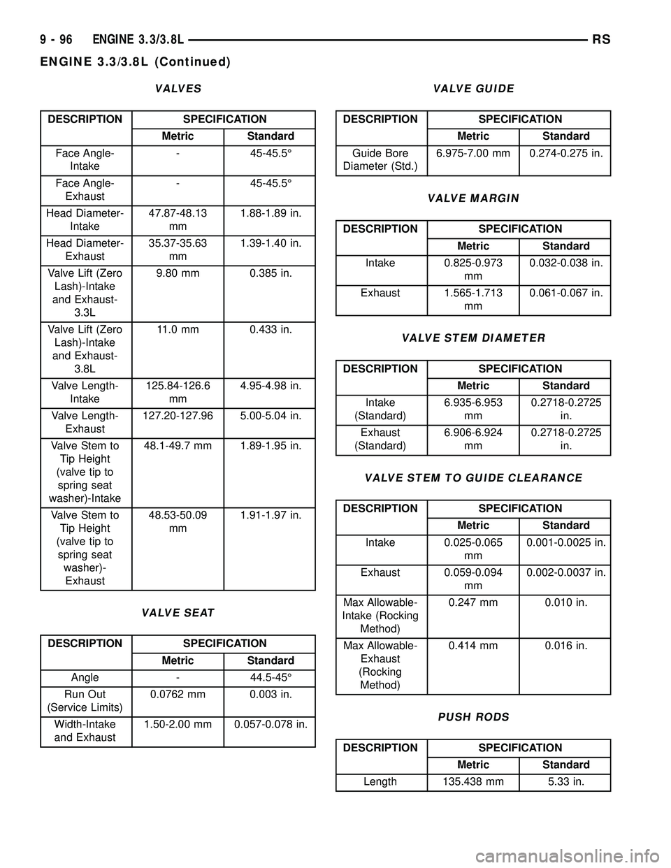
VALVES
DESCRIPTION SPECIFICATION
Metric Standard
Face Angle-
Intake- 45-45.5É
Face Angle-
Exhaust- 45-45.5É
Head Diameter-
Intake47.87-48.13
mm1.88-1.89 in.
Head Diameter-
Exhaust35.37-35.63
mm1.39-1.40 in.
Valve Lift (Zero
Lash)-Intake
and Exhaust-
3.3L9.80 mm 0.385 in.
Valve Lift (Zero
Lash)-Intake
and Exhaust-
3.8L11.0 mm 0.433 in.
Valve Length-
Intake125.84-126.6
mm4.95-4.98 in.
Valve Length-
Exhaust127.20-127.96 5.00-5.04 in.
Valve Stem to
Tip Height
(valve tip to
spring seat
washer)-Intake48.1-49.7 mm 1.89-1.95 in.
Valve Stem to
Tip Height
(valve tip to
spring seat
washer)-
Exhaust48.53-50.09
mm1.91-1.97 in.
VALVE SEAT
DESCRIPTION SPECIFICATION
Metric Standard
Angle - 44.5-45É
Run Out
(Service Limits)0.0762 mm 0.003 in.
Width-Intake
and Exhaust1.50-2.00 mm 0.057-0.078 in.
VALVE GUIDE
DESCRIPTION SPECIFICATION
Metric Standard
Guide Bore
Diameter (Std.)6.975-7.00 mm 0.274-0.275 in.
VALVE MARGIN
DESCRIPTION SPECIFICATION
Metric Standard
Intake 0.825-0.973
mm0.032-0.038 in.
Exhaust 1.565-1.713
mm0.061-0.067 in.
VALVE STEM DIAMETER
DESCRIPTION SPECIFICATION
Metric Standard
Intake
(Standard)6.935-6.953
mm0.2718-0.2725
in.
Exhaust
(Standard)6.906-6.924
mm0.2718-0.2725
in.
VALVE STEM TO GUIDE CLEARANCE
DESCRIPTION SPECIFICATION
Metric Standard
Intake 0.025-0.065
mm0.001-0.0025 in.
Exhaust 0.059-0.094
mm0.002-0.0037 in.
Max Allowable-
Intake (Rocking
Method)0.247 mm 0.010 in.
Max Allowable-
Exhaust
(Rocking
Method)0.414 mm 0.016 in.
PUSH RODS
DESCRIPTION SPECIFICATION
Metric Standard
Length 135.438 mm 5.33 in.
9 - 96 ENGINE 3.3/3.8LRS
ENGINE 3.3/3.8L (Continued)
Page 1274 of 2339
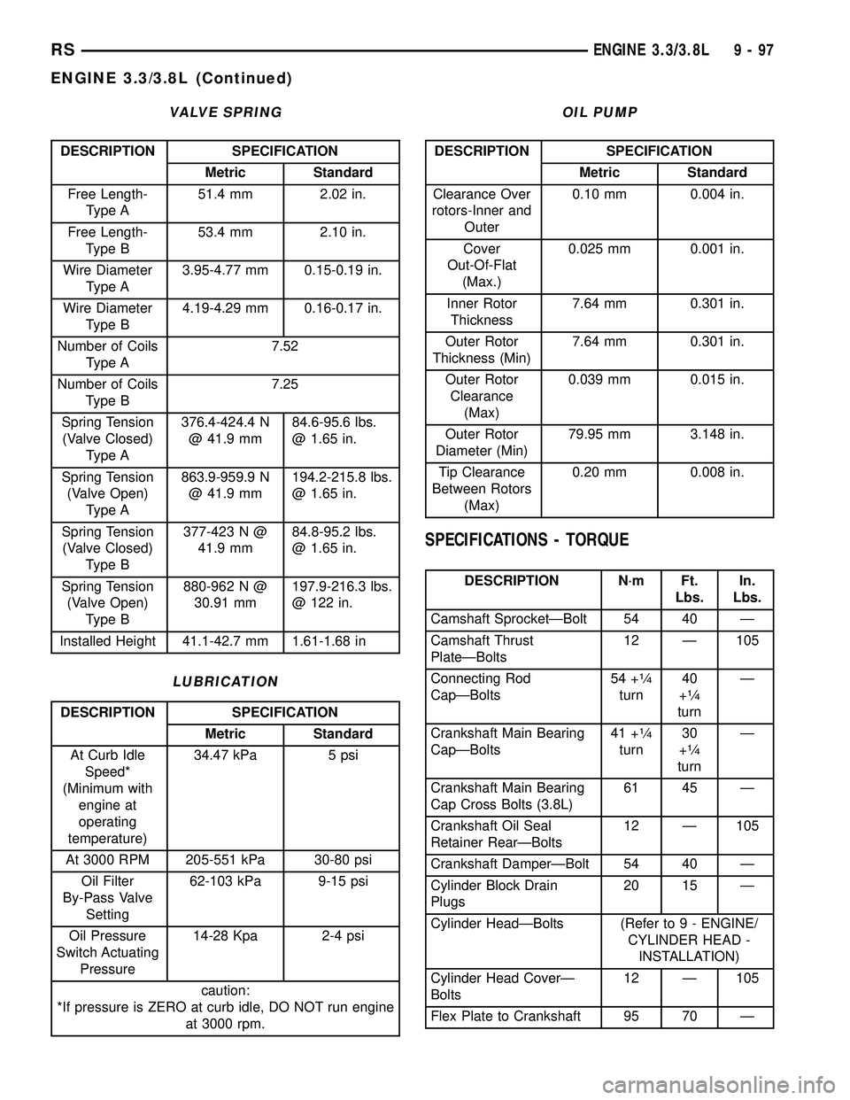
VALVE SPRING
DESCRIPTION SPECIFICATION
Metric Standard
Free Length-
Type A51.4 mm 2.02 in.
Free Length-
Type B53.4 mm 2.10 in.
Wire Diameter
Type A3.95-4.77 mm 0.15-0.19 in.
Wire Diameter
Type B4.19-4.29 mm 0.16-0.17 in.
Number of Coils
Type A7.52
Number of Coils
Type B7.25
Spring Tension
(Valve Closed)
Type A376.4-424.4 N
@ 41.9 mm84.6-95.6 lbs.
@ 1.65 in.
Spring Tension
(Valve Open)
Type A863.9-959.9 N
@ 41.9 mm194.2-215.8 lbs.
@ 1.65 in.
Spring Tension
(Valve Closed)
Type B377-423 N @
41.9 mm84.8-95.2 lbs.
@ 1.65 in.
Spring Tension
(Valve Open)
Type B880-962 N @
30.91 mm197.9-216.3 lbs.
@ 122 in.
Installed Height 41.1-42.7 mm 1.61-1.68 in
LUBRICATION
DESCRIPTION SPECIFICATION
Metric Standard
At Curb Idle
Speed*
(Minimum with
engine at
operating
temperature)34.47 kPa 5 psi
At 3000 RPM 205-551 kPa 30-80 psi
Oil Filter
By-Pass Valve
Setting62-103 kPa 9-15 psi
Oil Pressure
Switch Actuating
Pressure14-28 Kpa 2-4 psi
caution:
*If pressure is ZERO at curb idle, DO NOT run engine
at 3000 rpm.
OIL PUMP
DESCRIPTION SPECIFICATION
Metric Standard
Clearance Over
rotors-Inner and
Outer0.10 mm 0.004 in.
Cover
Out-Of-Flat
(Max.)0.025 mm 0.001 in.
Inner Rotor
Thickness7.64 mm 0.301 in.
Outer Rotor
Thickness (Min)7.64 mm 0.301 in.
Outer Rotor
Clearance
(Max)0.039 mm 0.015 in.
Outer Rotor
Diameter (Min)79.95 mm 3.148 in.
Tip Clearance
Between Rotors
(Max)0.20 mm 0.008 in.
SPECIFICATIONS - TORQUE
DESCRIPTION N´m Ft.
Lbs.In.
Lbs.
Camshaft SprocketÐBolt 54 40 Ð
Camshaft Thrust
PlateÐBolts12 Ð 105
Connecting Rod
CapÐBolts54 +
1¤4
turn40
+1¤4
turnÐ
Crankshaft Main Bearing
CapÐBolts41 +
1¤4
turn30
+1¤4
turnÐ
Crankshaft Main Bearing
Cap Cross Bolts (3.8L)61 45 Ð
Crankshaft Oil Seal
Retainer RearÐBolts12 Ð 105
Crankshaft DamperÐBolt 54 40 Ð
Cylinder Block Drain
Plugs20 15 Ð
Cylinder HeadÐBolts (Refer to 9 - ENGINE/
CYLINDER HEAD -
INSTALLATION)
Cylinder Head CoverÐ
Bolts12 Ð 105
Flex Plate to Crankshaft 95 70 Ð
RSENGINE 3.3/3.8L9-97
ENGINE 3.3/3.8L (Continued)
Page 1285 of 2339
NOTE: Valve seats which are worn or burned can
be reworked, provided that correct angle and seat
width are maintained. Otherwise cylinder head must
be replaced.
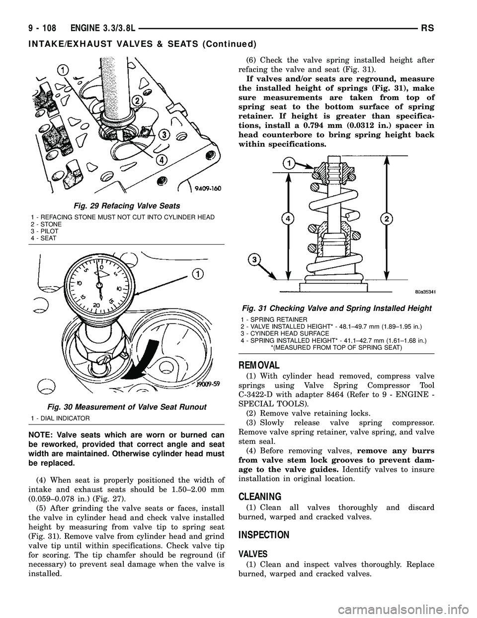
(4) When seat is properly positioned the width of
intake and exhaust seats should be 1.50±2.00 mm
(0.059±0.078 in.) (Fig. 27).
(5) After grinding the valve seats or faces, install
the valve in cylinder head and check valve installed
height by measuring from valve tip to spring seat
(Fig. 31). Remove valve from cylinder head and grind
valve tip until within specifications. Check valve tip
for scoring. The tip chamfer should be reground (if
necessary) to prevent seal damage when the valve is
installed.(6) Check the valve spring installed height after
refacing the valve and seat (Fig. 31).
If valves and/or seats are reground, measure
the installed height of springs (Fig. 31), make
sure measurements are taken from top of
spring seat to the bottom surface of spring
retainer. If height is greater than specifica-
tions, install a 0.794 mm (0.0312 in.) spacer in
head counterbore to bring spring height back
within specifications.
REMOVAL
(1) With cylinder head removed, compress valve
springs using Valve Spring Compressor Tool
C-3422-D with adapter 8464 (Refer to 9 - ENGINE -
SPECIAL TOOLS).
(2) Remove valve retaining locks.
(3) Slowly release valve spring compressor.
Remove valve spring retainer, valve spring, and valve
stem seal.
(4) Before removing valves,remove any burrs
from valve stem lock grooves to prevent dam-
age to the valve guides.Identify valves to insure
installation in original location.
CLEANING
(1) Clean all valves thoroughly and discard
burned, warped and cracked valves.
INSPECTION
VALVES
(1) Clean and inspect valves thoroughly. Replace
burned, warped and cracked valves.
Fig. 29 Refacing Valve Seats
1 - REFACING STONE MUST NOT CUT INTO CYLINDER HEAD
2-STONE
3 - PILOT
4 - SEAT
Fig. 30 Measurement of Valve Seat Runout
1 - DIAL INDICATOR
Fig. 31 Checking Valve and Spring Installed Height
1 - SPRING RETAINER
2 - VALVE INSTALLED HEIGHT* - 48.1±49.7 mm (1.89±1.95 in.)
3 - CYINDER HEAD SURFACE
4 - SPRING INSTALLED HEIGHT* - 41.1±42.7 mm (1.61±1.68 in.)
*(MEASURED FROM TOP OF SPRING SEAT)
9 - 108 ENGINE 3.3/3.8LRS
INTAKE/EXHAUST VALVES & SEATS (Continued)
Page 1288 of 2339
REMOVAL - CYLINDER HEAD ON
(1) Disconnect negative cable from battery.
(2) Remove spark plug wires and all spark plugs.
(3) Remove cylinder head cover(s). (Refer to 9 -
ENGINE/CYLINDER HEAD/CYLINDER HEAD
COVER(S) - REMOVAL)
(4) Remove rocker arms and shaft. (Refer to 9 -
ENGINE/CYLINDER HEAD/ROCKER ARMS -
REMOVAL)
(5) Rotate engine until the piston in the cylinder
bore requiring spring removal is at TDC.
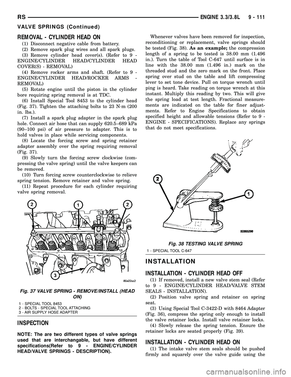
(6) Install Special Tool 8453 to the cylinder head
(Fig. 37). Tighten the attaching bolts to 23 N´m (200
in. lbs.).
(7) Install a spark plug adapter in the spark plug
hole. Connect air hose that can supply 620.5±689 kPa
(90±100 psi) of air pressure to adapter. This is to
hold valves in place while servicing components.
(8) Locate the forcing screw and spring retainer
adapter assembly over the spring requiring removal
(Fig. 37).
(9) Slowly turn the forcing screw clockwise (com-
pressing the valve spring) until the valve keepers can
be removed.
(10) Turn forcing screw counterclockwise to relieve
spring tension. Remove retainer and valve spring.
(11) Repeat procedure for each cylinder requiring
valve spring removal.
INSPECTION
NOTE: The are two different types of valve springs
used that are interchangable, but have different
specifications(Refer to 9 - ENGINE/CYLINDER
HEAD/VALVE SPRINGS - DESCRIPTION).Whenever valves have been removed for inspection,
reconditioning or replacement, valve springs should
be tested (Fig. 38).As an example;the compression
length of a spring to be tested is 38.00 mm (1.496
in.). Turn the table of Tool C-647 until surface is in
line with the 38.00 mm (1.496 in.) mark on the
threaded stud and the zero mark on the front. Place
spring over stud on the table and lift compressing
lever to set tone device. Pull on torque wrench until
ping is heard. Take reading on torque wrench at this
instant. Multiply this reading by two. This will give
the spring load at test length. Fractional measure-
ments are indicated on the table for finer adjust-
ments. Refer to Engine Specifications to obtain
specified height and allowable tensions (Refer to 9 -
ENGINE - SPECIFICATIONS). Replace any springs
that do not meet specifications.
INSTALLATION
INSTALLATION - CYLINDER HEAD OFF
(1) If removed, install a new valve stem seal (Refer
to 9 - ENGINE/CYLINDER HEAD/VALVE STEM
SEALS - INSTALLATION).
(2) Position valve spring and retainer on spring
seat.
(3) Using Special Tool C-3422-D with 8464 Adapter
(Fig. 36), compress the spring only enough to install
the valve retainer locks. Install valve retainer locks.
(4) Slowly release the spring tension. Ensure the
retainer locks are seated properly (Fig. 39).
INSTALLATION - CYLINDER HEAD ON
(1) The intake valve stem seals should be pushed
firmly and squarely over the valve guide using the
Fig. 37 VALVE SPRING - REMOVE/INSTALL (HEAD
ON)
1 - SPECIAL TOOL 8453
2 - BOLTS - SPECIAL TOOL ATTACHING
3 - AIR SUPPLY HOSE ADAPTER
Fig. 38 TESTING VALVE SPRING
1 - SPECIAL TOOL C-647
RSENGINE 3.3/3.8L9 - 111
VALVE SPRINGS (Continued)
Page 1289 of 2339
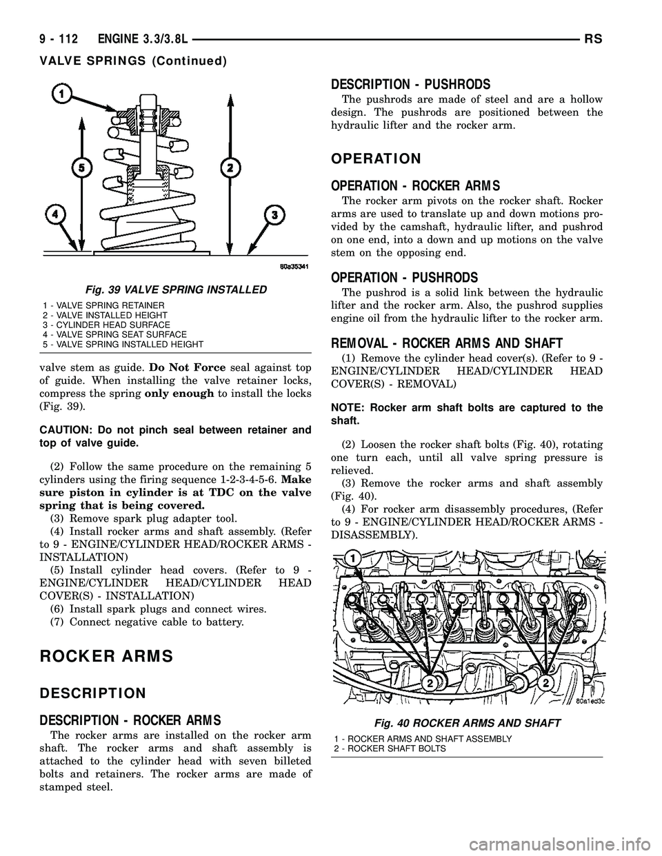
valve stem as guide.Do Not Forceseal against top
of guide. When installing the valve retainer locks,
compress the springonly enoughto install the locks
(Fig. 39).
CAUTION: Do not pinch seal between retainer and
top of valve guide.
(2) Follow the same procedure on the remaining 5
cylinders using the firing sequence 1-2-3-4-5-6.Make
sure piston in cylinder is at TDC on the valve
spring that is being covered.
(3) Remove spark plug adapter tool.
(4) Install rocker arms and shaft assembly. (Refer
to 9 - ENGINE/CYLINDER HEAD/ROCKER ARMS -
INSTALLATION)
(5) Install cylinder head covers. (Refer to 9 -
ENGINE/CYLINDER HEAD/CYLINDER HEAD
COVER(S) - INSTALLATION)
(6) Install spark plugs and connect wires.
(7) Connect negative cable to battery.
ROCKER ARMS
DESCRIPTION
DESCRIPTION - ROCKER ARMS
The rocker arms are installed on the rocker arm
shaft. The rocker arms and shaft assembly is
attached to the cylinder head with seven billeted
bolts and retainers. The rocker arms are made of
stamped steel.
DESCRIPTION - PUSHRODS
The pushrods are made of steel and are a hollow
design. The pushrods are positioned between the
hydraulic lifter and the rocker arm.
OPERATION
OPERATION - ROCKER ARMS
The rocker arm pivots on the rocker shaft. Rocker
arms are used to translate up and down motions pro-
vided by the camshaft, hydraulic lifter, and pushrod
on one end, into a down and up motions on the valve
stem on the opposing end.
OPERATION - PUSHRODS
The pushrod is a solid link between the hydraulic
lifter and the rocker arm. Also, the pushrod supplies
engine oil from the hydraulic lifter to the rocker arm.
REMOVAL - ROCKER ARMS AND SHAFT
(1) Remove the cylinder head cover(s). (Refer to 9 -
ENGINE/CYLINDER HEAD/CYLINDER HEAD
COVER(S) - REMOVAL)
NOTE: Rocker arm shaft bolts are captured to the
shaft.
(2) Loosen the rocker shaft bolts (Fig. 40), rotating
one turn each, until all valve spring pressure is
relieved.
(3) Remove the rocker arms and shaft assembly
(Fig. 40).
(4) For rocker arm disassembly procedures, (Refer
to 9 - ENGINE/CYLINDER HEAD/ROCKER ARMS -
DISASSEMBLY).
Fig. 39 VALVE SPRING INSTALLED
1 - VALVE SPRING RETAINER
2 - VALVE INSTALLED HEIGHT
3 - CYLINDER HEAD SURFACE
4 - VALVE SPRING SEAT SURFACE
5 - VALVE SPRING INSTALLED HEIGHT
Fig. 40 ROCKER ARMS AND SHAFT
1 - ROCKER ARMS AND SHAFT ASSEMBLY
2 - ROCKER SHAFT BOLTS
9 - 112 ENGINE 3.3/3.8LRS
VALVE SPRINGS (Continued)
Page 1353 of 2339
(3) Align and insert the center forward tab.
(4) Align the remaining tabs and press into the
slots, starting in the center and working outboard.
(5) Assure all tabs are fully engaged into the fas-
cia.
(6) If rear bumper fascia has been removed install.
(Refer to 13 - FRAME & BUMPERS/BUMPERS/
REAR FASCIA - INSTALLATION).
FRAME
SPECIFICATIONS
SPECIFICATIONS - FRAME DIMENSIONS
Frame dimensions are listed in metric scale. All
dimensions are from center to center of PrincipalLocating Point (PLP), or from center to center of PLP
and fastener location.
VEHICLE PREPARATION
Position the vehicle on a frame alignment rack,
refer to instructions provided with equipment being
used. Adjust the vehicle PLP heights to the specified
dimension above the work surface (datum line). Ver-
tical dimensions can be taken from the datum line to
the locations indicated were applicable.
INDEX
DESCRIPTION FIGURE
CROSSMEMBER DIMENSIONS 8
ENGINE BOX - TOP VIEW 9
ENGINE COMPARTMENT AND FRAME RAIL - SIDE VIEW 10
FULL VEHICLE - BOTTOM VIEW 11
13 - 6 FRAME & BUMPERSRS
REAR FASCIA - SCUFF PAD (Continued)
Page 1770 of 2339
TIRES
DESCRIPTION
DESCRIPTION - TIRE
Tires are designed and engineered for each specific
vehicle. They provide the best overall performance
for normal operation. The ride and handling charac-
teristics match the vehicle's requirements. With
proper care they will give excellent reliability, trac-
tion, skid resistance, and tread life.
Driving habits have more effect on tire life than
any other factor. Careful drivers will obtain, in most
cases, much greater mileage than severe use or care-
less drivers. A few of the driving habits which will
shorten the life of any tire are:
²Rapid acceleration
²Severe application of brakes
²High-speed driving
²Taking turns at excessive speeds
²Striking curbs and other obstacles
²Operating vehicle with over or under inflated
tire pressures
Radial ply tires are more prone to irregular tread
wear. It is important to follow the tire rotation inter-
val shown in the section on Tire Rotation. This will
help to achieve a greater tread-life potential.
TIRE IDENTIFICATION
Tire type, size, load index and speed rating are
encoded in the letters and numbers imprinted on the
side wall of the tire. Refer to the Tire Identification
chart to decipher the code. For example purposes, the
tire size P225/60 R 16 97 T is used in the chart. An
All Season type tire will also have eitherM+S,M&
SorM-S(indicating mud and snow traction)
imprinted on the side wall. An Extra or Light Load
marking ªXLº or ªLLº may also be listed on the side-
wall. The absence of an ªXLº or ªLLº marking infers
a standard load tire.
TIRE IDENTIFICATION
PTIRE TYPE (Not
present on all tires)P - Passenger
T - Temporary
C - Commercial
LT - Light Truck
225SECTIONAL WIDTHSHOWN IN
MILLIMETERS
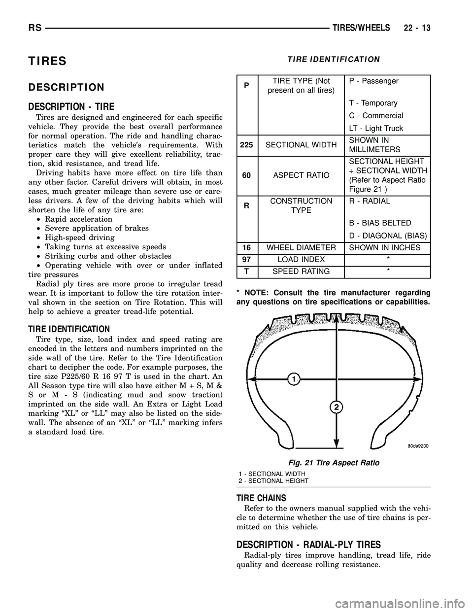
60ASPECT RATIOSECTIONAL HEIGHT
÷ SECTIONAL WIDTH
(Refer to Aspect Ratio
Figure 21 )
RCONSTRUCTION
TYPER - RADIAL
B - BIAS BELTED
D - DIAGONAL (BIAS)
16WHEEL DIAMETER SHOWN IN INCHES
97LOAD INDEX *
TSPEED RATING *
* NOTE: Consult the tire manufacturer regarding
any questions on tire specifications or capabilities.
TIRE CHAINS
Refer to the owners manual supplied with the vehi-
cle to determine whether the use of tire chains is per-
mitted on this vehicle.
DESCRIPTION - RADIAL-PLY TIRES
Radial-ply tires improve handling, tread life, ride
quality and decrease rolling resistance.
Fig. 21 Tire Aspect Ratio
1 - SECTIONAL WIDTH
2 - SECTIONAL HEIGHT
RSTIRES/WHEELS22-13
Page 1790 of 2339
DESCRIPTION N´m Ft. Lbs. In. Lbs.
Front cover to seat track screws 4 Ð 32
Front door hinge to hinge pillar bolts 34 25 Ð
Front door hinge to door nuts and bolts 34 25 Ð
Front door latch striker bolts 28 21 Ð
Front/quad seat cushion bolts 28.5 21 Ð
Front seat belt retractor bolts 38 28 Ð
Front seat riser to floor nuts 60 44 Ð
Front seat track cover screws 4 Ð 35
Front seat riser to seat track nuts 81 60 Ð
Front seatback pivot bolts 54 40 Ð
Front seatback recliner nut 12 Ð 105
Front seatback assist strap screws 2.5 Ð 22
Grocery bag holder screws 2 Ð 17
Hinge to liftgate bolts 33 24 Ð
Hood latch to bolts 13.5 10 Ð
Hood latch striker bolts 13.5 10 Ð
Hood hinge to hood bolts 13.5 10 Ð
Liftgate exterior handle outer screws 20 15 Ð
Liftgate exterior handle inner bolts 40 30 Ð
Lifgate hinge to roof header bolts 33 24 Ð
Liftgate latch bolts 16 12 Ð
Liftgate latch striker bolts 28 21 Ð
Liftgate lift motor link to liftgate 28 21 Ð
Liftgate spoiler bolts 9 Ð 80
Lifgate stabilizer wedge striker to D-pillar bolts 3 Ð 30
Luggage rack crossbar fasteners 4 Ð 35
Lumbar support handle screw 1 Ð 9
Pivot bolt to the body half of hood hinge 28 21 Ð
Prop assembly to lifgate bolts 28 21 Ð
Rear door glass to regulator bolt 11 8 Ð
Rear door hinge to B-pillar bolt 28 20 Ð
Rear door hinge to door bolt 28 20 Ð
Rear door latch striker 28 20 Ð
Rear latch to sliding door end frame 28 20 Ð
Rear seat back to seat cushion bolt 27 19 Ð
Recliner to seat back frame 12 9 Ð
Seatback frame upper rail 8 Ð 71
Seatback hinge bolt 48 35 Ð
Seatback hinge cover screws 2.3 Ð 20
Shoulder belt turning loop onto height adjuster 39 29 Ð
Side view mirror bolts 10 Ð 85
Sliding door center hinge adjusting bolt 15 Ð 130
RSBODY23-11
BODY (Continued)