2005 CHRYSLER CARAVAN transmission
[x] Cancel search: transmissionPage 2226 of 2339
²The upper bolt at the rear of the compressor.
²The lower bolt at the rear of the compressor.
(4) Connect the wire harness connector to the com-
pressor clutch coil wire connector.
(5) Install the accessory drive belt (Refer to 7 -
COOLING/ACCESSORY DRIVE/DRIVE BELTS -
INSTALLATION).
(6) Lower the vehicle.
(7) Remove the tape or plugs from the suction and
discharge line fittings and the compressor ports.
(8) Lubricate new rubber O-ring seals with clean
refrigerant oil and install them and a new gasket
onto the suction and discharge line fittings.
(9) Connect the A/C suction line and the A/C dis-
charge line to the A/C compressor.
(10) Install the nut that secures the A/C suction
line and the A/C discharge line to the A/C compres-
sor. Tighten the nuts to 23 N´m (17 ft. lbs.).
(11) Reconnect the negative battery cable.
(12) Evacuate the refrigerant system (Refer to 24 -
HEATING & AIR CONDITIONING/PLUMBING -
FRONT/REFRIGERANT - STANDARD PROCE-
DURE - REFRIGERANT SYSTEM EVACUATE).
(13) Charge the refrigerant system (Refer to 24 -
HEATING & AIR CONDITIONING/PLUMBING -
FRONT/REFRIGERANT - STANDARD PROCE-
DURE - REFRIGERANT SYSTEM CHARGE).
A/C COMPRESSOR MOUNTING BRACKET -
2.4L ENGINE
(1) Position the compressor mounting bracket onto
the engine.
(2) Install the four bolts that secure the compres-
sor mounting bracket to the engine. Tighten the bolts
to 54 N´m (40 ft. lbs.).
(3) Reinstall the A/C compressor onto the mount-
ing bracket (Refer to 24 - HEATING & AIR CONDI-
TIONING/PLUMBING/COMPRESSOR -
INSTALLATION).
A/C CONDENSER
DESCRIPTION
The A/C condenser is located in the front of the
engine compartment behind the front fascia. The A/C
condenser is a heat exchanger that allows the high-
pressure refrigerant gas being discharged by the A/C
compressor to give up its heat to the air passing over
the condenser fins, which causes the refrigerant to
cool and change to a liquid state.The A/C condenser may be removed for service
without removing the radiator and cooling fan from
the vehicle.
The A/C condenser for vehicles equipped with the
2.4L/3.3L/3.8L engines are equipped with an integral
automatic transmission cooler and mounting provi-
sions.
OPERATION
When air passes through the fins of the A/C con-
denser, the high-pressure refrigerant gas within the
A/C condenser gives up its heat. The refrigerant then
condenses as it leaves the A/C condenser and
becomes a high-pressure liquid. The volume of air
flowing over the condenser fins is critical to the
proper cooling performance of the A/C system. There-
fore, it is important that there are no objects placed
in front of the radiator grille openings at the front of
the vehicle or foreign material on the condenser fins
that might obstruct proper air flow. Also, any factory-
installed air seals or shrouds must be properly rein-
stalled following radiator or A/C condenser service.
The A/C condenser cannot be repaired and, if
faulty or damaged, it must be replaced.
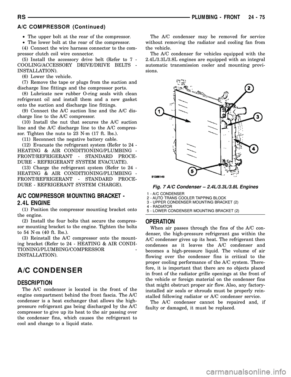
Fig. 7 A/C Condenser ± 2.4L/3.3L/3.8L Engines
1 - A/C CONDENSER
2 - AUTO TRANS COOLER TAPPING BLOCK
3 - UPPER CONDENSER MOUNTING BRACKET (2)
4 - RADIATOR
5 - LOWER CONDENSER MOUNTING BRACKET (2)
RSPLUMBING - FRONT24-75
A/C COMPRESSOR (Continued)
Page 2227 of 2339
REMOVAL
2.4L/3.3L/3.8L ENGINES
WARNING: REFER TO THE APPLICABLE WARN-
INGS AND CAUTIONS FOR THIS SYSTEM BEFORE
PERFORMING THE FOLLOWING OPERATION (Refer
to 24 - HEATING & AIR CONDITIONING/PLUMBING -
FRONT - WARNING - A/C PLUMBING) and (Refer to
24 - HEATING & AIR CONDITIONING/PLUMBING -
FRONT - CAUTION - A/C PLUMBING).
NOTE: Before removing the A/C condenser, note the
location of each of the radiator and condenser air
seals. These air seals are used to direct air through
the A/C condenser and radiator. The air seals must
be reinstalled in their proper locations in order for
the A/C and engine cooling systems to perform as
designed.
(1) Recover the refrigerant from the refrigerant
system (Refer to 24 - HEATING & AIR CONDITION-
ING/PLUMBING - FRONT/REFRIGERANT - STAN-
DARD PROCEDURE - REFRIGERANT SYSTEM
RECOVERY).
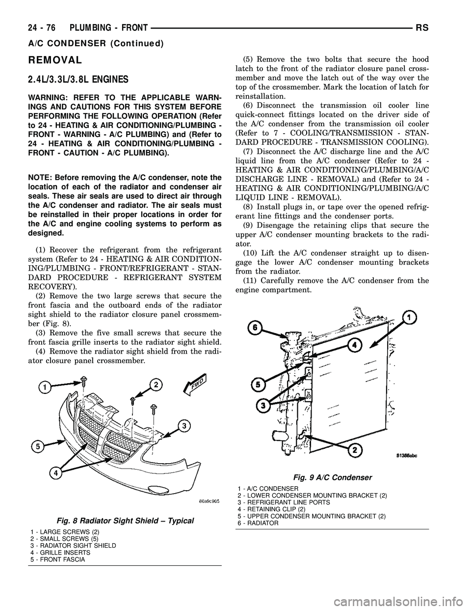
(2) Remove the two large screws that secure the
front fascia and the outboard ends of the radiator
sight shield to the radiator closure panel crossmem-
ber (Fig. 8).
(3) Remove the five small screws that secure the
front fascia grille inserts to the radiator sight shield.
(4) Remove the radiator sight shield from the radi-
ator closure panel crossmember.(5) Remove the two bolts that secure the hood
latch to the front of the radiator closure panel cross-
member and move the latch out of the way over the
top of the crossmember. Mark the location of latch for
reinstallation.
(6) Disconnect the transmission oil cooler line
quick-connect fittings located on the driver side of
the A/C condenser from the transmission oil cooler
(Refer to 7 - COOLING/TRANSMISSION - STAN-
DARD PROCEDURE - TRANSMISSION COOLING).
(7) Disconnect the A/C discharge line and the A/C
liquid line from the A/C condenser (Refer to 24 -
HEATING & AIR CONDITIONING/PLUMBING/A/C
DISCHARGE LINE - REMOVAL) and (Refer to 24 -
HEATING & AIR CONDITIONING/PLUMBING/A/C
LIQUID LINE - REMOVAL).
(8) Install plugs in, or tape over the opened refrig-
erant line fittings and the condenser ports.
(9) Disengage the retaining clips that secure the
upper A/C condenser mounting brackets to the radi-
ator.
(10) Lift the A/C condenser straight up to disen-
gage the lower A/C condenser mounting brackets
from the radiator.
(11) Carefully remove the A/C condenser from the
engine compartment.
Fig. 8 Radiator Sight Shield ± Typical
1 - LARGE SCREWS (2)
2 - SMALL SCREWS (5)
3 - RADIATOR SIGHT SHIELD
4 - GRILLE INSERTS
5 - FRONT FASCIA
Fig. 9 A/C Condenser
1 - A/C CONDENSER
2 - LOWER CONDENSER MOUNTING BRACKET (2)
3 - REFRIGERANT LINE PORTS
4 - RETAINING CLIP (2)
5 - UPPER CONDENSER MOUNTING BRACKET (2)
6 - RADIATOR
24 - 76 PLUMBING - FRONTRS
A/C CONDENSER (Continued)
Page 2228 of 2339
2.5L/2.8L DIESEL ENGINES
WARNING: REFER TO THE APPLICABLE WARN-
INGS AND CAUTIONS FOR THIS SYSTEM BEFORE
PERFORMING THE FOLLOWING OPERATION (Refer
to 24 - HEATING & AIR CONDITIONING/PLUMBING -
FRONT - WARNING - A/C PLUMBING) and (Refer to
24 - HEATING & AIR CONDITIONING/PLUMBING -
FRONT - CAUTION - A/C PLUMBING).
NOTE: Before removing the A/C condenser, note the
location of each of the radiator and condenser air
seals. These air seals are used to direct air through
the A/C condenser and radiator. The air seals must
be reinstalled in their proper locations in order for
the A/C and engine cooling systems to perform as
designed.
(1) Recover the refrigerant from the refrigerant
system (Refer to 24 - HEATING & AIR CONDITION-
ING/PLUMBING - FRONT/REFRIGERANT - STAN-
DARD PROCEDURE - REFRIGERANT SYSTEM
RECOVERY).
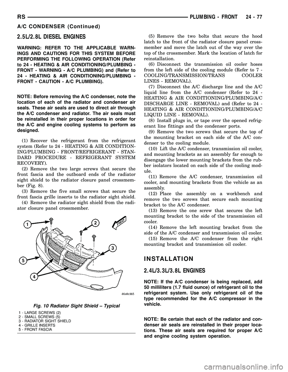
(2) Remove the two large screws that secure the
front fascia and the outboard ends of the radiator
sight shield to the radiator closure panel crossmem-
ber (Fig. 8).
(3) Remove the five small screws that secure the
front fascia grille inserts to the radiator sight shield.
(4) Remove the radiator sight shield from the radi-
ator closure panel crossmember.(5) Remove the two bolts that secure the hood
latch to the front of the radiator closure panel cross-
member and move the latch out of the way over the
top of the crossmember. Mark the location of latch for
reinstallation.
(6) Disconnect the transmission oil cooler hoses
from the left side of the cooling module (Refer to 7 -
COOLING/TRANSMISSION/TRANS COOLER
LINES - REMOVAL).
(7) Disconnect the A/C discharge line and the A/C
liquid line from the A/C condenser (Refer to 24 -
HEATING & AIR CONDITIONING/PLUMBING/A/C
DISCHARGE LINE - REMOVAL) and (Refer to 24 -
HEATING & AIR CONDITIONING/PLUMBING/A/C
LIQUID LINE - REMOVAL).
(8) Install plugs in, or tape over the opened refrig-
erant line fittings and the condenser ports.
(9) Remove the two screws that secure the top of
the mounting bracket on each side of the A/C con-
denser to the cooling module.
(10) Lift the A/C condenser, transmission oil cooler,
and mounting brackets as an assembly far enough to
disengage the lower mounting brackets from the rub-
ber isolators located on each side of the cooling mod-
ule.
(11) Remove the A/C condenser, transmission oil
cooler, and mounting brackets from the vehicle as an
assembly.
(12) Place the assembly on a workbench and
remove the two screws that secure each mounting
bracket to the A/C condenser.
(13) Remove the one screw that secures the left
mounting bracket to the side of the transmission oil
cooler.
(14) Remove the left mounting bracket from the
side of the A/C condenser and transmission oil cooler.
(15) Remove the A/C condenser from the right
mounting bracket and transmission oil cooler.
INSTALLATION
2.4L/3.3L/3.8L ENGINES
NOTE: If the A/C condenser is being replaced, add
50 milliliters (1.7 fluid ounce) of refrigerant oil to the
refrigerant system. Use only refrigerant oil of the
type recommended for the A/C compressor in the
vehicle.
NOTE: Be certain that each of the radiator and con-
denser air seals are reinstalled in their proper loca-
tions. These air seals are required for proper A/C
and engine cooling system operation.
Fig. 10 Radiator Sight Shield ± Typical
1 - LARGE SCREWS (2)
2 - SMALL SCREWS (5)
3 - RADIATOR SIGHT SHIELD
4 - GRILLE INSERTS
5 - FRONT FASCIA
RSPLUMBING - FRONT24-77
A/C CONDENSER (Continued)
Page 2229 of 2339

(1) Position the A/C condenser into the engine
compartment.
(2) Carefully lower the A/C condenser straight
down to engage the lower mounting brackets to the
radiator.
(3) Engage the upper A/C condenser mounting
brackets to the radiator. Be sure that the upper
retaining clips are fully engaged to the upper mount-
ing brackets.
(4) Remove the tape or plugs from the opened
refrigerant line fittings and the condenser ports.
(5) Connect the A/C discharge line and the A/C liq-
uid line to the A/C condenser (Refer to 24 - HEAT-
ING & AIR CONDITIONING/PLUMBING/A/C
DISCHARGE LINE - INSTALLATION) and (Refer to
24 - HEATING & AIR CONDITIONING/PLUMBING/
A/C LIQUID LINE - INSTALLATION).
(6) Connect the transmission oil cooler lines to the
A/C Condenser. Be sure that the quick-connect fit-
tings are fully engaged to the cooler tapping block
(Refer to 7 - COOLING/TRANSMISSION - STAN-
DARD PROCEDURE - TRANSMISSION COOLING).
(7) Position the hood latch onto the front of the
radiator closure panel crossmember.
(8) Install the two screws that secure the hood
latch to the crossmember. Check and adjust the hoodlatch as required. Tighten the bolts to 14 N´m (123
in. lbs.).
(9) Position the radiator sight shield onto the radi-
ator closure panel crossmember.
(10) Install the five small screws that secure the
front fascia grille inserts to the radiator sight shield.
Tighten the screws to 2 N´m (17 in. lbs.).
(11) Install the two large screws that secure the
front fascia and the outboard ends of the radiator
sight shield to the radiator closure panel crossmem-
ber. Tighten the screws to 6 N´m (53 in. lbs.).
(12) Evacuate the refrigerant system (Refer to 24 -
HEATING & AIR CONDITIONING/PLUMBING -
FRONT/REFRIGERANT - STANDARD PROCE-
DURE - REFRIGERANT SYSTEM EVACUATE).
(13) Charge the refrigerant system (Refer to 24 -
HEATING & AIR CONDITIONING/PLUMBING -
FRONT/REFRIGERANT - STANDARD PROCE-
DURE - REFRIGERANT SYSTEM CHARGE).
2.5L/2.8L DIESEL ENGINES
NOTE: If the A/C condenser is being replaced, add
50 milliliters (1.7 fluid ounce) of refrigerant oil to the
refrigerant system. Use only refrigerant oil of the
type recommended for the A/C compressor in the
vehicle.
NOTE: Be certain that each of the radiator and con-
denser air seals are reinstalled in their proper loca-
tions. These air seals are required for proper A/C
and engine cooling system operation.
(1) Position the A/C condenser onto the right
mounting bracket and transmission oil cooler unit.
(2) Position the left mounting bracket onto the side
of the A/C condenser and transmission oil cooler.
(3) Install the screw that secures the left mounting
bracket to the side of the transmission oil cooler.
Tighten the screw to 5 N´m (45 in. lbs.).
(4) Install the two screws that secure each mount-
ing bracket to the sides of the A/C condenser. Tighten
the screws to 5 N´m (45 in. lbs.).
NOTE: Verify that the A/C condenser isolators are
all installed and positioned correctly.
(5) Position the A/C condenser, transmission oil
cooler, and mounting brackets into the vehicle as an
assembly. Be certain that the lower mounting brack-
ets are engaged into the rubber isolators located on
each side of the cooling module.
(6) Install the two screws that secure the top of
the mounting bracket on each side of the A/C con-
denser to the cooling module. Tighten the screws to 5
N´m (45 in. lbs.).
Fig. 11 A/C Condenser ± 2.5L/2.8L Diesel Engines
1 - BOLT (2)
2 - LOWER MOUNT ISOLATOR (2)
3 - A/C CONDENSER
24 - 78 PLUMBING - FRONTRS
A/C CONDENSER (Continued)
Page 2230 of 2339
(7) Remove the tape or plugs from the opened
refrigerant line fittings and the condenser ports.
(8) Connect the A/C discharge line and the A/C liq-
uid line to the A/C condenser (Refer to 24 - HEAT-
ING & AIR CONDITIONING/PLUMBING/A/C
DISCHARGE LINE - INSTALLATION) and (Refer to
24 - HEATING & AIR CONDITIONING/PLUMBING/
A/C LIQUID LINE - INSTALLATION).
(9) Reconnect the hoses to the transmission oil
cooler fittings on the left side of the cooling module
(Refer to 7 - COOLING/TRANSMISSION/TRANS
COOLER LINES - INSTALLATION).
(10) Reposition the hood latch to the front of the
radiator closure panel crossmember.
(11) Install the two screws that secure the hood
latch to the front of the radiator closure panel cross-
member. Check and adjust the hood latch as needed.
Tighten the screws to 14 N´m (123 in. lbs.).
(12) Position the radiator sight shield onto the
radiator closure panel crossmember.
(13) Install the five small screws that secure the
front fascia grille inserts to the radiator sight shield.
Tighten the screws to 2 N´m (17 in. lbs.).
(14) Install the two large screws that secure the
front fascia and the outboard ends of the radiator
sight shield to the radiator closure panel crossmem-
ber. Tighten the screws to 6 N´m (53 in. lbs.).
(15) Evacuate the refrigerant system (Refer to 24 -
HEATING & AIR CONDITIONING/PLUMBING -
FRONT/REFRIGERANT - STANDARD PROCE-
DURE - REFRIGERANT SYSTEM EVACUATE).
(16) Charge the refrigerant system (Refer to 24 -
HEATING & AIR CONDITIONING/PLUMBING -
FRONT/REFRIGERANT - STANDARD PROCE-
DURE - REFRIGERANT SYSTEM CHARGE).
A/C DISCHARGE LINE
REMOVAL
WARNING: REFER TO THE APPLICABLE WARN-
INGS AND CAUTIONS FOR THIS SYSTEM BEFORE
PERFORMING THE FOLLOWING OPERATION (Refer
to 24 - HEATING & AIR CONDITIONING/PLUMBING -
FRONT - WARNING - A/C PLUMBING) and (Refer to
24 - HEATING & AIR CONDITIONING/PLUMBING -
FRONT - CAUTION - A/C PLUMBING).
(1) Recover the refrigerant from the refrigerant
system (Refer to 24 - HEATING & AIR CONDITION-
ING/PLUMBING - FRONT/REFRIGERANT - STAN-
DARD PROCEDURE - REFRIGERANT SYSTEM
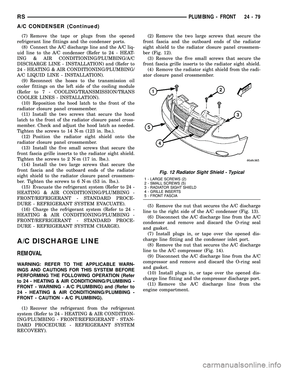
RECOVERY).(2) Remove the two large screws that secure the
front fascia and the outboard ends of the radiator
sight shield to the radiator closure panel crossmem-
ber (Fig. 12).
(3) Remove the five small screws that secure the
front fascia grille inserts to the radiator sight shield.
(4) Remove the radiator sight shield from the radi-
ator closure panel crossmember.
(5) Remove the nut that secures the A/C discharge
line to the right side of the A/C condenser (Fig. 13).
(6) Disconnect the A/C discharge line from the A/C
condenser and remove and discard the O-ring seal
and gasket.
(7) Install plugs in, or tape over the opened dis-
charge line fitting and the condenser inlet port.
(8) Remove the nut that secures the A/C discharge
line to the A/C compressor (Fig. 14).
(9) Disconnect the A/C discharge line from the A/C
compressor and remove and discard the O-ring seal
and gasket.
(10) Install plugs in, or tape over the opened dis-
charge line fitting and the compressor discharge port.
(11) Remove the A/C discharge line from the
engine compartment.
Fig. 12 Radiator Sight Shield - Typical
1 - LARGE SCREWS (2)
2 - SMALL SCREWS (5)
3 - RADIATOR SIGHT SHIELD
4 - GRILLE INSERTS
5 - FRONT FASCIA
RSPLUMBING - FRONT24-79
A/C CONDENSER (Continued)
Page 2276 of 2339
richer than optimum A/F mixture or vice versa. As
the PCM adjusts the air/fuel ratio, the sensor must
be able to rapidly detect the change. As the sensor
ages, it could take longer to detect the changes in the
oxygen content of the exhaust gas. The rate of
change that an oxygen sensor experiences is called
'Big Slope'. The PCM checks the oxygen sensor volt-
age in increments of a few milliseconds.
Reduced Output Voltage (Half Cycle)ÐThe
output voltage of the O2S ranges from 0 to 1 volt. A
good sensor can easily generate any output voltage in
this range as it is exposed to different concentrations
of oxygen. To detect a shift in the A/F mixture (lean
or rich), the output voltage has to change beyond a
threshold value. A malfunctioning sensor could have
difficulty changing beyond the threshold value. Many
times the condition is only temporey and the sensor
will recover. Under normal conditions the voltage sig-
nal surpasses the threshold, and a counter is incre-
mented by one. This is called the Half Cycle Counter.
Heater PerformanceÐThe heater is tested by a
separate monitor. Refer to the Oxygen Sensor Heater
Monitor.
OPERATIONÐAs the Oxygen Sensor signal
switches, the PCM monitors the half cycle and big
slope signals from the oxygen sensor. If during the
test neither counter reaches a predetermined value, a
malfunction is entered and a Freeze Frame is stored.
Only one counter reaching its predetermined value is
needed for the monitor to pass.
The Oxygen Sensor Signal Monitor is a two trip
monitor that is tested only once per trip. When the
Oxygen Sensor fails the test in two consecutive trips,
the MIL is illuminated and a DTC is set. The MIL is
extinguished when the Oxygen Sensor monitor
passes in three consecutive trips. The DTC is erased
from memory after 40 consecutive warm-up cycles
without test failure.
Enabling ConditionsÐThe following conditions
must typically be met for the PCM to run the oxygen
sensor monitor:
²Battery voltage
²Engine temperature
²Engine run time
²Engine run time at a predetermined speed
²Engine run time at a predetermined speed and
throttle opening
²Transmission in gear (automatic only)
²Fuel system in Closed Loop
²Long Term Adaptive (within parameters)
²Power Steering Switch in low PSI (no load)
²Engine at idle
²Fuel level above 15%
²Ambient air temperature
²Barometric pressure²Engine RPM within acceptable range of desired
idle
²Closed throttle speed
Pending ConditionsÐThe Task Manager typi-
cally does not run the Oxygen Sensor Signal Monitor
if overlapping monitors are running or the MIL is
illuminated for any of the following:
²Misfire Monitor
²Front Oxygen Sensor and Heater Monitor
²MAP Sensor
²Vehicle Speed Sensor
²Engine Coolant Temperature Sensor
²Throttle Position Sensor
²Engine Controller Self Test Faults
²Cam or Crank Sensor
²Injector and Coil
²Idle Air Control Motor
²EVAP Electrical
²EGR Solenoid Electrical
²Intake Air Temperature
²5 Volt Feed
ConflictÐThe Task Manager does not run the
Oxygen Sensor Monitor if any of the following condi-
tions are present:
²A/C ON (A/C clutch cycling temporarily sus-
pends monitor)
²Purge flow in progress
²Ethenal content learn is taking place and the
ethenal used once flag is set
SuspendÐThe Task Manager suspends maturing
a fault for the Oxygen Sensor Monitor if an of the fol-
lowing are present:
²Oxygen Sensor Heater Monitor, Priority 1
²Misfire Monitor, Priority 2
OXYGEN SENSOR HEATER MONITOR (NGC)
DESCRIPTIONÐIf the Oxygen sensor (O2S) DTC
as well as a O2S heater DTC is present, the O2S
Heater DTC MUST be repaired first. After the O2S
Heater is repaired, verify that the sensor circuit is
operating correctly.
The voltage reading taken from the O2S are very
temperature sensitive. The readings taken from the
O2S are not accurate below 300 degrees C. Heating
the O2S is done to allow the engine controller to shift
to closed loop control as soon as possible. The heating
element used to heat the O2S must be tested to
ensure that it is heating the sensor properly. Starting
with the introduction on the NGC module the strat-
egy for checking the heater circuit has changed. The
heater resistance is checked by the NGC almost
immediately after the engine is started. The same
O2S heater return pin used to read the heater resis-
tance is capable of detecting an open circuit, a
shorted high or shorted low condition.
RSEMISSIONS CONTROL25-3
EMISSIONS CONTROL (Continued)
Page 2306 of 2339
BRAKE CABLES - ADJUSTMENT,PARKING ............................ 5-65
BRAKE CALIPER - INSTALLATION, REAR DISC ............................... 5-30
BRAKE CALIPER - REMOVAL, REAR DISC ............................... 5-28
BRAKE CALIPER ADAPTER - INSTALLATION, FRONT DISC .............5-31
BRAKE CALIPER ADAPTER - REMOVAL, FRONT DISC ......................... 5-31
BRAKE CALIPER (CONTINENTAL TEVES BRAKES) - INSTALLATION, FRONT
DISC ............................... 5-27
BRAKE CALIPER (CONTINENTAL TEVES BRAKES) - REMOVAL, FRONT DISC .......5-24
BRAKE CALIPER GUIDE PINS (TRW BRAKES) - INSTALLATION, DISC .........5-32
BRAKE CALIPER GUIDE PINS (TRW BRAKES) - REMOVAL, DISC .............5-31
BRAKE CALIPER (TRW BRAKES) - INSTALLATION, FRONT DISC .............5-27
BRAKE CALIPER (TRW BRAKES) - REMOVAL, FRONT DISC ................5-24
BRAKE FASTENER TORQUE, SPECIFICATIONS .......................5-9
BRAKE FLUID CONTAMINATION - DIAGNOSIS AND TESTING ..............5-33
BRAKE FLUID LEVEL CHECKING - STANDARD PROCEDURE ................5-33
BRAKE FLUID LEVEL SWITCH - DESCRIPTION ........................ 5-10
BRAKE FLUID LEVEL SWITCH - INSTALLATION ........................ 5-11
BRAKE FLUID LEVEL SWITCH - OPERATION .......................... 5-10
BRAKE FLUID LEVEL SWITCH - REMOVAL ........................... 5-11
BRAKE FLUID, SPECIFICATIONS ..........5-33
BRAKE INTERMEDIATE - INSTALLATION, CABLE - PARKING ..................... 5-69
BRAKE INTERMEDIATE - REMOVAL, CABLE - PARKING ..................... 5-69
BRAKE LAMP SWITCH - DESCRIPTION ....8L-4
BRAKE LAMP SWITCH - DIAGNOSIS AND TESTING ........................ 8L-4
BRAKE LAMP SWITCH - INSTALLATION ....8L-5
BRAKE LAMP SWITCH - OPERATION ......8L-4
BRAKE LAMP SWITCH - REMOVAL .......8L-5
BRAKE LEVER AND FRONT CABLE - INSTALLATION, PARKING ...............5-77
BRAKE LEVER AND FRONT CABLE - REMOVAL, PARKING ................... 5-77
BRAKE PROPORTIONING - DESCRIPTION, ELECTRONIC VARIABLE ....5-88
BRAKE PROPORTIONING - OPERATION, ELECTRONIC VARIABLE ................5-89
BRAKE ROTOR - DIAGNOSIS AND TESTING ............................ 5-55
BRAKE ROTOR - INSTALLATION, FRONT . . . 5-59
BRAKE ROTOR - REMOVAL, FRONT .......5-59
BRAKE ROTOR, EXPORT ................5-60
BRAKE ROTOR MACHINING - STANDARD PROCEDURE ......................... 5-58
BRAKE ROTOR, SPECIFICATIONS .........5-60
BRAKE SHOE LINING - INSPECTION, REAR DRUM ......................... 5-22
BRAKE SHOES - ADJUSTMENT, PARKING . . 5-85
BRAKE SHOES - ADJUSTMENT, REAR DRUM .............................. 5-23
BRAKE SHOES - CLEANING, DISC ....5-16,5-18
BRAKE SHOES - INSPECTION, DISC . . . 5-16,5-18
BRAKE SHOES - INSTALLATION, REAR DISC ............................... 5-19
BRAKE SHOES - INSTALLATION, REAR DRUM .............................. 5-22
BRAKE SHOES - REMOVAL, REAR DISC ....5-17
BRAKE SHOES - REMOVAL, REAR DRUM . . 5-19
BRAKE SHOES (CONTINENTAL TEVES BRAKES) - INSTALLATION, FRONT
DISC ............................... 5-16
BRAKE SHOES (CONTINENTAL TEVES BRAKES) - REMOVAL, FRONT DISC .......5-15
BRAKE SHOES (TRW BRAKES) - INSTALLATION, FRONT DISC .............5-17
BRAKE SHOES (TRW BRAKES) - REMOVAL, FRONT DISC ................5-15
BRAKE SYSTEM - DESCRIPTION, ANTILOCK ........................... 5-87BRAKE SYSTEM - DIAGNOSIS AND
TESTING, BASE ........................5-4
BRAKE SYSTEM - OPERATION, ANTILOCK ........................... 5-88
BRAKE SYSTEM BLEEDING - STANDARD PROCEDURE, ANTILOCK ................5-90
BRAKE SYSTEM (EXPORT) - DESCRIPTION, ANTILOCK ...............5-87
BRAKE SYSTEM, SPECIAL TOOLS - BASE . . 5-10
BRAKE TUBES AND HOSES - DESCRIPTION ........................ 5-14
BRAKE TUBES AND HOSES - INSPECTION ......................... 5-14
BRAKE TUBES AND HOSES - OPERATION . . 5-14
BRAKES - DESCRIPTION, BASE ...........5-3
BRAKES - OPERATION, BASE .............5-3
BRAKES (EXPORT) - DESCRIPTION, BASE ................................5-3
BRAKES (EXPORT) - DESCRIPTION, DISC . . 5-13
BRAKES (FRONT) - DESCRIPTION, DISC . . . 5-11
BRAKES (FRONT) - OPERATION, DISC .....5-13
BRAKES (REAR) - DESCRIPTION, DISC ....5-13
BRAKES (REAR) - DESCRIPTION, DRUM . . . 5-13
BRAKES (REAR) - OPERATION, DISC ......5-14
BRAKE/TRANSMISSION SHIFT INTERLOCK SOLENOID - DIAGNOSIS
AND TESTING ................ 21-115,21-266
BREAK-IN, STANDARD PROCEDURE - A/C CLUTCH ........................ 24-15
BUCKET - INSTALLATION, BUCKET SEAT BACK - QUAD ........................ 23-141
BUCKET - INSTALLATION, SEAT BELT BUCKLE - FIRST ROW INBOARD -
QUAD ............................. 8O-36
BUCKET - REMOVAL, BUCKET SEAT BACK - QUAD ...................... 23-140
BUCKET - REMOVAL, SEAT BELT BUCKLE - FIRST ROW INBOARD - QUAD .........8O-35
BUCKET, 50/50 SPLIT, BENCH - INSTALLATION, SEAT BACK HINGE
COVERS - QUAD .................... 23-146
BUCKET, 50/50 SPLIT, BENCH - INSTALLATION, SEAT CUSHION COVER
- QUAD ........................... 23-144
BUCKET, 50/50 SPLIT, BENCH - REMOVAL, SEAT BACK HINGE COVERS
- QUAD ........................... 23-146
BUCKET, 50/50 SPLIT, BENCH - REMOVAL, SEAT CUSHION COVER -
QUAD ............................. 23-144
BUCKET SEAT BACK - QUAD BUCKET - INSTALLATION ...................... 23-141
BUCKET SEAT BACK - QUAD BUCKET - REMOVAL ......................... 23-140
BUCKET SEAT RISER - INSTALLATION, QUAD ............................. 23-143
BUCKET SEAT RISER - REMOVAL, QUAD . 23-143
BUCKET SEAT SIDE SHIELD - NO CUP HOLDER - INSTALLATION, QUAD .......23-143
BUCKET SEAT SIDE SHIELD - NO CUP HOLDER - REMOVAL, QUAD ...........23-143
BUCKET SEAT SIDE SHIELD/CUP HOLDER - FLAP AND SPRING
ASSEMBLY - INSTALLATION, QUAD .....23-151
BUCKET SEAT SIDE SHIELD/CUP HOLDER - FLAP AND SPRING
ASSEMBLY - REMOVAL, QUAD .........23-151
BUCKET SEAT SIDE SHIELD/CUP HOLDER - INSTALLATION, QUAD .......23-142
BUCKET SEAT SIDE SHIELD/CUP HOLDER - REMOVAL, QUAD ...........23-141
BUCKLE - FIRST ROW - BENCH - INSTALLATION, SEAT BELT .............8O-37
BUCKLE - FIRST ROW - BENCH - REMOVAL, SEAT BELT ................8O-36
BUCKLE - FIRST ROW INBOARD - QUAD BUCKET - INSTALLATION, SEAT BELT ....8O-36
BUCKLE - FIRST ROW INBOARD - QUAD BUCKET - REMOVAL, SEAT BELT ........8O-35
BUCKLE - FRONT INBOARD - INSTALLATION, SEAT BELT .............8O-35
BUCKLE - FRONT INBOARD - REMOVAL, SEAT BELT ......................... 8O-35
BUCKLE - SECOND ROW - THREE PASSENGER BENCH - INSTALLATION,
SEAT BELT ......................... 8O-40BUCKLE - SECOND ROW - THREE
PASSENGER BENCH - REMOVAL, SEAT
BELT .............................. 8O-40
BUCKLE - SECOND ROW INBOARD - 50/50 BENCH - INSTALLATION, SEAT
BELT .............................. 8O-38
BUCKLE - SECOND ROW INBOARD - 50/50 BENCH - REMOVAL, SEAT BELT ....8O-37
BUMPER - DESCRIPTION, JOUNCE ........2-35
BUMPER - INSTALLATION, STOP ........23-25
BUMPER - OPERATION, JOUNCE .........2-35
BUMPER - REMOVAL, STOP ............23-25
BUMPER BEZEL - INSTALLATION, SLIDING DOOR STOP .................23-25
BUMPER BEZEL - REMOVAL, SLIDING DOOR STOP ........................ 23-25
BUMPER REINFORCEMENT - INSTALLATION, FRONT .................13-3
BUMPER REINFORCEMENT - INSTALLATION, REAR .................. 13-5
BUMPER REINFORCEMENT - REMOVAL, FRONT .............................. 13-3
BUMPER REINFORCEMENT - REMOVAL, REAR ............................... 13-5
BUS COMMUNICATION RECEIVE - PCM INPUT - OPERATION, DATA .............8E-14
BUS, OPERATION - PROGRAMMABLE COMMUNICATIONS INTERFACE (PCI) .....14-25
BUSHING - LEAF SPRING FRONT - INSTALLATION ........................ 2-30
BUSHING - LEAF SPRING FRONT - REMOVAL ........................... 2-29
BUSHINGS - INSTALLATION, FRONT CROSSMEMBER MOUNT ...............13-17
BUSHINGS - REMOVAL, FRONT CROSSMEMBER MOUNT ...............13-17
BUSHINGS (CONTINENTAL TEVES BRAKES) - ASSEMBLY, CALIPER GUIDE
PIN ................................ 5-25
BUSHINGS (CONTINENTAL TEVES BRAKES) - DISASSEMBLY, CALIPER
GUIDE PIN ........................... 5-24
CABIN HEATER - DESCRIPTION ........24-113
CABIN HEATER, DIAGNOSIS AND TESTING - SUPPLEMENTAL ...........24-114
CABLE - DESCRIPTION .................8P-4
CABLE - DESCRIPTION, ANTENNA BODY . . . 8A-7
CABLE - DESCRIPTION, SPARK PLUG .....8I-10
CABLE - INSTALLATION ................8P-4
CABLE - INSTALLATION, GEAR SHIFT ....21-234
CABLE - INSTALLATION, HOLD OPEN LATCH ............................. 23-38
CABLE - INSTALLATION, INSIDE HANDLE . . 23-38
CABLE - INSTALLATION, INSTRUMENT PANEL ANTENNA ..................... 8A-12
CABLE - INSTALLATION, LATCH RELEASE . 23-64
CABLE - INSTALLATION, OUTSIDE HANDLE ............................ 23-37
CABLE - INSTALLATION, PARKING BRAKE LEVER AND FRONT ..............5-77
CABLE - INSTALLATION, THROTTLE CONTROL .......................... 14-40
CABLE - OPERATION ................... 8P-4
CABLE - OPERATION, ANTENNA BODY .....8A-7
CABLE - PARKING BRAKE INTERMEDIATE - INSTALLATION ..........5-69
CABLE - PARKING BRAKE INTERMEDIATE - REMOVAL .............5-69
CABLE - REMOVAL .................... 8P-4
CABLE - REMOVAL, GEAR SHIFT . . 21-233,21-84
CABLE - REMOVAL, HOLD OPEN LATCH . . . 23-38
CABLE - REMOVAL, INSIDE HANDLE .....23-37
CABLE - REMOVAL, INSTRUMENT PANEL ANTENNA .......................... 8A-12
CABLE - REMOVAL, LATCH RELEASE .....23-63
CABLE - REMOVAL, OUTSIDE HANDLE ....23-37
CABLE - REMOVAL, PARKING BRAKE LEVER AND FRONT .................... 5-77
CABLE - REMOVAL, THROTTLE CONTROL .......................... 14-40
CABLE ADJUSTMENT, ADJUSTMENTS - GEARSHIFT ........................ 21-235
CABLE ADJUSTMENT, INSTALLATION - SYNCHRONIZING ..............23-105,23-147
CABLE, DIAGNOSIS AND TESTING - ANTENNA BODY ...................... 8A-8
RS INDEX5
Description Group-Page Description Group-Page Description Group-Page
Page 2308 of 2339
CHIRP PREFERENCE - STANDARDPROCEDURE, HORN .................. 8N-24
CIRCUIT, DIAGNOSIS AND TESTING - AMBIENT TEMPERATURE SENSOR ......8M-12
CIRCUIT FUNCTIONS - DESCRIPTION . . 8W-01-6
CIRCUIT INFORMATION - DESCRIPTION . 8W-01-5
CIRCUIT RESISTANCE TEST - DIAGNOSIS AND TESTING, FEED ........8F-35
CIRCUIT TEST - DIAGNOSIS AND TESTING, CONTROL .................. 8F-33
CIRCUIT TEST - DIAGNOSIS AND TESTING, FEED ...................... 8F-36
CIRCUITS AND VALVES - OPERATION, HYDRAULIC .......................... 5-95
CIRCUITS, DESCRIPTION - NON- MONITORED ......................... 25-5
CLAMP - STANDARD PROCEDURE, HOSES .............................. 14-7
CLAMPS - DESCRIPTION, FUEL LINES/HOSES ........................ 14-7
CLAMPS - DESCRIPTION, HOSE ...........7-1
CLAMPS - OPERATION, HOSE .............7-2
CLASSIFICATION MODULE - DESCRIPTION, OCCUPANT .............8O-25
CLASSIFICATION MODULE - INSTALLATION, OCCUPANT ............8O-26
CLASSIFICATION MODULE - OPERATION, OCCUPANT ......................... 8O-25
CLASSIFICATION MODULE - REMOVAL, OCCUPANT ......................... 8O-26
CLEARANCE - STANDARD PROCEDURE, MEASURING CONNECTING ROD
BEARING ............................ 9-123
CLEARANCE USING PLASTIGAGE - STANDARD PROCEDURE, MEASURING
BEARING ........................ 9-12,9-86
CLOCKSPRING - DESCRIPTION .........8O-10
CLOCKSPRING - INSTALLATION .........8O-12
CLOCKSPRING - OPERATION ...........8O-11
CLOCKSPRING - REMOVAL ............8O-12
CLOCKSPRING CENTERING - STANDARD PROCEDURE ........................ 8O-11
CLUSTER - DESCRIPTION, INSTRUMENT . . . 8J-1
CLUSTER - OPERATION, INSTRUMENT .....8J-1
CLUSTER BEZEL - INSTALLATION ........23-65
CLUSTER BEZEL - REMOVAL ...........23-65
CLUSTER DIAGNOSIS - DIAGNOSIS AND TESTING ............................ 8J-3
CLUSTER ILLUMINATION LAMPS - INSTALLATION ....................... 8L-21
CLUSTER ILLUMINATION LAMPS - REMOVAL .......................... 8L-21
CLUSTER LENS - INSTALLATION ........8J-11
CLUSTER LENS - REMOVAL ............8J-11
CLUTCH AIR PRESSURE TESTS - DIAGNOSIS AND TESTING ........21-153,21-8
CLUTCH ASSEMBLY - ASSEMBLY, INPUT ....................... 21-246,21-95
CLUTCH ASSEMBLY - DISASSEMBLY, INPUT ....................... 21-237,21-86
CLUTCH BREAK-IN, STANDARD PROCEDURE - A/C ................... 24-15
CLUTCH COIL, DIAGNOSIS AND TESTING - A/C COMPRESSOR .................. 24-14
CLUTCH INSPECTION, STANDARD PROCEDURE ........................ 24-15
CLUTCH RELAY - DESCRIPTION, A/C COMPRESSOR ....................... 24-18
CLUTCH RELAY - INSTALLATION, A/C COMPRESSOR ....................... 24-19
CLUTCH RELAY - OPERATION, A/C COMPRESSOR ....................... 24-18
CLUTCH RELAY - REMOVAL, A/C COMPRESSOR ....................... 24-19
CLUTCH/COIL - DESCRIPTION, A/C COMPRESSOR ....................... 24-13
CLUTCH/COIL - OPERATION, A/C COMPRESSOR ....................... 24-13
CLUTCHES - DESCRIPTION, DRIVING . . . 21-219,
21-74
CLUTCHES - DESCRIPTION, HOLDING . . . 21-236,
21-86
CLUTCHES - OPERATION, DRIVING .....21-219,
21-74
CLUTCHES - OPERATION, HOLDING ....21-236,
21-86
COAT/CLEARCOAT FINISH - DESCRIPTION, BASE .................23-101CODE - DESCRIPTION, PAINT
..........23-101
CODE CHARTS - SPECIFICATIONS, COLOR ............................ 23-100
CODES - STANDARD PROCEDURE, OBTAINING DIAGNOSTIC TROUBLE ......8E-15
CODES, STANDARD PROCEDURE - ERASING TRANSMITTER ..............8M-12
CODES, STANDARD PROCEDURE - SETTING TRANSMITTER ..............8M-12
COIL - DESCRIPTION, IGNITION ..........8I-6
COIL - OPERATION, IGNITION ............8I-6
COIL, DIAGNOSIS AND TESTING - A/C COMPRESSOR CLUTCH ...............24-14
COLLAR - INSTALLATION, STRUCTURAL . . . 9-49
COLLAR - REMOVAL, STRUCTURAL .......9-49
COLOR CODE CHARTS - SPECIFICATIONS .................... 23-100
COLUMN - DESCRIPTION, STEERING .....19-10
COLUMN - DIAGNOSIS AND TESTING, STEERING .......................... 19-11
COLUMN COVER - INSTALLATION, LOWER STEERING ................... 23-74
COLUMN COVER - INSTALLATION, OVER STEERING .......................... 23-76
COLUMN COVER - REMOVAL, LOWER STEERING .......................... 23-74
COLUMN COVER - REMOVAL, OVER STEERING .......................... 23-76
COLUMN FASTENER TORQUE, SPECIFICATIONS ..................... 19-17
COMBUSTION PRESSURE LEAKAGE TEST - DIAGNOSIS AND TESTING,
CYLINDER ........................ 9-85,9-9
COMMUNICATION RECEIVE - PCM INPUT - OPERATION, DATA BUS ..............8E-14
COMMUNICATIONS INTERFACE (PCI) BUS, OPERATION - PROGRAMMABLE ....14-25
COMPASS CALIBRATION, STANDARD PROCEDURE ......................... 8M-4
COMPASS DEMAGNETIZING, STANDARD PROCEDURE ......................... 8M-5
COMPASS MINI-TRIP COMPUTER, DIAGNOSIS AND TESTING .............8M-10
COMPASS VARIATION ADJUSTMENT, STANDARD PROCEDURE ...............8M-5
COMPASS/MINI-TRIP COMPUTER - DESCRIPTION ....................... 8M-10
COMPASS/MINI-TRIP COMPUTER - OPERATION ........................ 8M-10
COMPRESSION PRESSURE TEST - DIAGNOSIS AND TESTING, CYLINDER . . 9-85,9-9
COMPRESSOR CLUTCH COIL, DIAGNOSIS AND TESTING - A/ C.........24-14
COMPRESSOR CLUTCH RELAY - DESCRIPTION, A/C ................... 24-18
COMPRESSOR CLUTCH RELAY - INSTALLATION, A/C ................... 24-19
COMPRESSOR CLUTCH RELAY - OPERATION, A/C ..................... 24-18
COMPRESSOR CLUTCH RELAY - REMOVAL, A/C ...................... 24-19
COMPRESSOR CLUTCH/COIL - DESCRIPTION, A/C ................... 24-13
COMPRESSOR CLUTCH/COIL - OPERATION, A/C ..................... 24-13
COMPRESSOR, DESCRIPTION - A/C ......24-72
COMPRESSOR, INSTALLATION - A/C .....24-74
COMPRESSOR MOUNTING BRACKET, 2.4L ENGINE - A/C ..............24-74,24-75
COMPRESSOR NOISE DIAGNOSIS, DIAGNOSIS AND TESTING - A/C .........24-72
COMPRESSOR, OPERATION - A/C ........24-72
COMPRESSOR, REMOVAL - A/C .........24-73
COMPUTER - DESCRIPTION, COMPASS/ MINI-TRIP ......................... 8M-10
COMPUTER - OPERATION, COMPASS/ MINI-TRIP ......................... 8M-10
COMPUTER, DIAGNOSIS AND TESTING - COMPASS MINI-TRIP .................8M-10
CONCENTRATION TESTING - DIAGNOSIS AND TESTING, COOLANT ...............7-19
CONDENSER - DESCRIPTION, A/C .......24-75
CONDENSER - OPERATION, A/C .........24-75
CONDITION CHECK, STANDARD PROCEDURE - FLUID LEVEL ......21-230,21-82
CONDITIONER, DESCRIPTION - HEATER AND AIR ............................ 24-1CONDITIONER, OPERATION - HEATER
AND AIR ............................ 24-4
CONNECT FITTING DISASSEMBLY/ ASSEMBLY - STANDARD PROCEDURE,
TRANSMISSION COOLER LINE QUICK .....7-38
CONNECTING ROD - DESCRIPTION, PISTON ........................ 9-119,9-44
CONNECTING ROD - INSTALLATION, PISTON ............................. 9-45
CONNECTING ROD - REMOVAL, PISTON . . . 9-44
CONNECTING ROD BEARING CLEARANCE - STANDARD
PROCEDURE, MEASURING .............9-123
CONNECTING ROD, FITTING .............9-46
CONNECTING RODS - STANDARD PROCEDURE, FITTING .................9-119
CONNECTOR - DESCRIPTION, DATA LINK . . 8E-6
CONNECTOR - INSTALLATION .......8W-01-11
CONNECTOR - OPERATION, DATA LINK ....8E-6
CONNECTOR - REMOVAL ...........8W-01-11
CONNECTOR, GROUND AND SPLICE INFORMATION - DESCRIPTION ........8W-01-7
CONNECTOR/GROUND/SPLICE LOCATION - DESCRIPTION ....................8W -91-1
CONSOLE - DESCRIPTION, OVERHEAD ....8M-2
CONSOLE - FOLD-IN-FLOOR - INSTALLATION, FLOOR ................23-89
CONSOLE - FOLD-IN-FLOOR - REMOVAL, FLOOR ............................. 23-89
CONSOLE - INSTALLATION, LOWER ......23-73
CONSOLE - REMOVAL, LOWER ..........23-73
CONSOLE BASE TRAY - INSTALLATION, FLOOR ............................. 23-89
CONSOLE BASE TRAY - REMOVAL, FLOOR ............................. 23-89
CONSOLE, DIAGNOSIS AND TESTING - OVERHEAD .......................... 8M-3
CONSOLE KEY LOCK TUMBLER - FOLD-IN-FLOOR - INSTALLATION,
FLOOR ............................. 23-90
CONSOLE KEY LOCK TUMBLER - FOLD-IN-FLOOR - REMOVAL, FLOOR .....23-90
CONSOLE LAMP - INSTALLATION, CENTER ............................ 8L-21
CONSOLE LAMP - REMOVAL, CENTER ....8L-21
CONSOLE LAMP SWITCH - INSTALLATION, CENTER ...............8L-21
CONSOLE LAMP SWITCH - REMOVAL, CENTER ............................ 8L-21
CONSOLE LID LATCH - FOLD-IN-FLOOR - INSTALLATION, FLOOR ................23-90
CONSOLE LID LATCH - FOLD-IN-FLOOR - REMOVAL, FLOOR .................... 23-90
CONSOLE, SPECIAL TOOLS - OVERHEAD . . 8M-7
CONTAINER - DESCRIPTION, COOLANT RECOVERY .......................... 7-20
CONTAINER - INSTALLATION, COOLANT RECOVERY .......................... 7-20
CONTAINER - OPERATION, COOLANT RECOVERY .......................... 7-20
CONTAINER - REMOVAL, COOLANT RECOVERY .......................... 7-20
CONTAMINATION - DIAGNOSIS AND TESTING, BRAKE FLUID ................5-33
CONTINUITY - STANDARD PROCEDURE, TESTING .........................8W -01-9
CONTROL (4 SPEED EATX ONLY) - OPERATION, INTERACTIVE SPEED ........8P-2
CONTROL ARM - DESCRIPTION, LOWER . . . 2-12
CONTROL ARM - INSPECTION, LOWER ....2-14
CONTROL ARM - INSTALLATION, LOWER . . 2-15
CONTROL ARM - OPERATION, LOWER .....2-12
CONTROL ARM - REMOVAL, LOWER ......2-12
CONTROL ARM (REAR BUSHING - HYDRO) - ASSEMBLY, LOWER ...........2-15
CONTROL ARM (REAR BUSHING - HYDRO) - DISASSEMBLY, LOWER ........2-13
CONTROL ARM (REAR BUSHING - STANDARD) - ASSEMBLY, LOWER ........2-14
CONTROL ARM (REAR BUSHING - STANDARD) - DISASSEMBLY, LOWER .....2-13
CONTROL CABLE - INSTALLATION, THROTTLE .......................... 14-40
CONTROL CABLE - REMOVAL, THROTTLE .......................... 14-40
CONTROL CALIBRATION, STANDARD PROCEDURE - A/C-HEATER .............24-19
RS INDEX7
Description Group-Page Description Group-Page Description Group-Page