2005 CHRYSLER CARAVAN instrument panel
[x] Cancel search: instrument panelPage 2201 of 2339
INSTALLATION
WARNING: ON VEHICLES EQUIPPED WITH AIR-
BAGS, DISABLE THE AIRBAG SYSTEM BEFORE
ATTEMPTING ANY STEERING WHEEL, STEERING
COLUMN, OR INSTRUMENT PANEL COMPONENT
DIAGNOSIS OR SERVICE. DISCONNECT AND ISO-
LATE THE BATTERY NEGATIVE (GROUND) CABLE,
THEN WAIT TWO MINUTES FOR THE AIRBAG SYS-
TEM CAPACITOR TO DISCHARGE BEFORE PER-
FORMING FURTHER DIAGNOSIS OR SERVICE. THIS
IS THE ONLY SURE WAY TO DISABLE THE AIRBAG
SYSTEM. FAILURE TO TAKE THE PROPER PRECAU-
TIONS COULD RESULT IN ACCIDENTAL AIRBAG
DEPLOYMENT AND POSSIBLE PERSONAL INJURY.
(1) Position the defroster duct to the instrument
panel.
(2) Install the fasteners that secure the defroster
duct to the instrument panel armature.
(3) Reinstall the instrument panel in the vehicle.
(Refer to 23 - BODY/INSTRUMENT PANEL/INSTRU-
MENT PANEL ASSEMBLY - INSTALLATION).
(4) Reconnect the battery negative cable.
FLOOR DISTRIBUTION DUCTS
REMOVAL
(1) Roll back the carpet on the front floor from
under the instrument panel toward the rear of the
vehicle (Refer to 23 - BODY/INTERIOR/CARPETS
AND FLOOR MATS - REMOVAL).
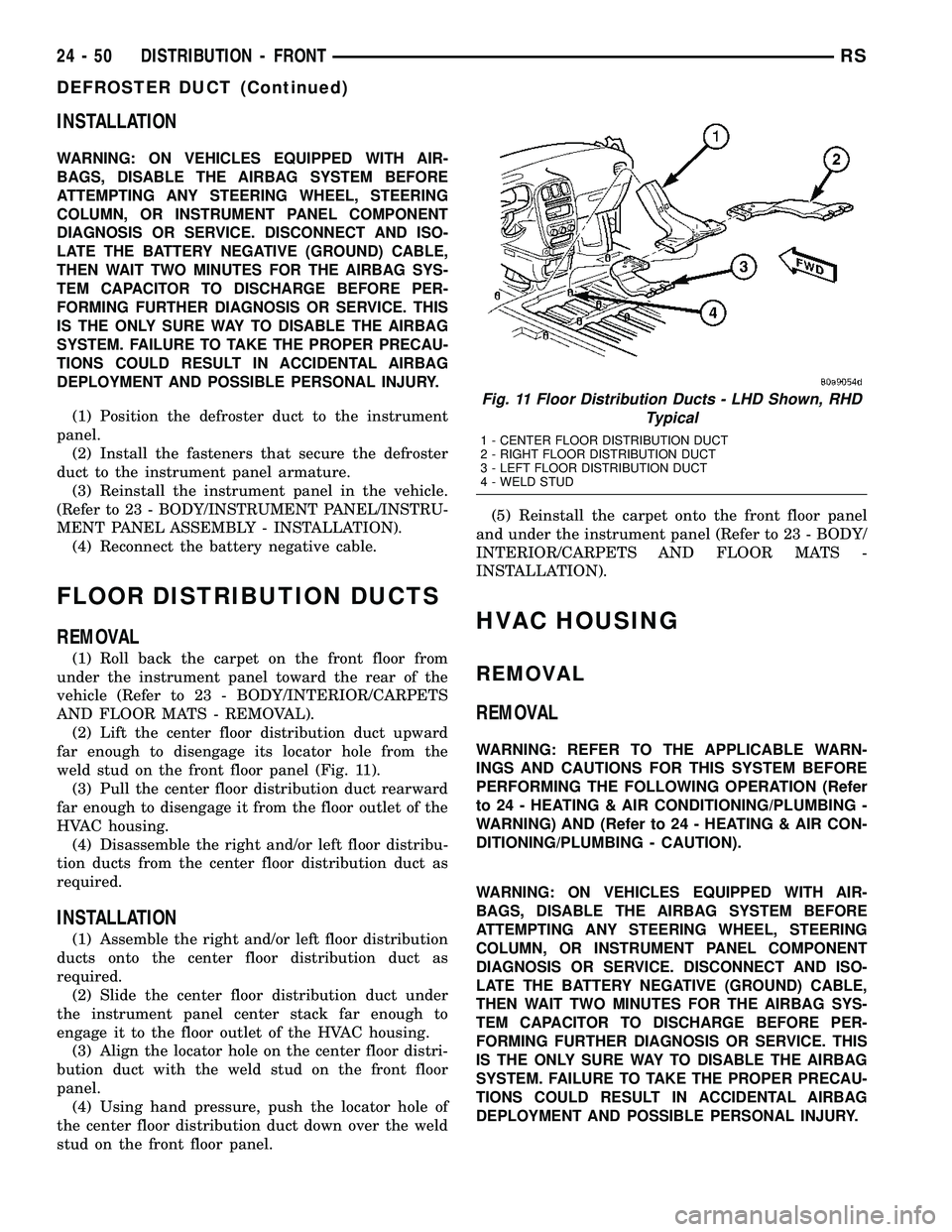
(2) Lift the center floor distribution duct upward
far enough to disengage its locator hole from the
weld stud on the front floor panel (Fig. 11).
(3) Pull the center floor distribution duct rearward
far enough to disengage it from the floor outlet of the
HVAC housing.
(4) Disassemble the right and/or left floor distribu-
tion ducts from the center floor distribution duct as
required.
INSTALLATION
(1) Assemble the right and/or left floor distribution
ducts onto the center floor distribution duct as
required.
(2) Slide the center floor distribution duct under
the instrument panel center stack far enough to
engage it to the floor outlet of the HVAC housing.
(3) Align the locator hole on the center floor distri-
bution duct with the weld stud on the front floor
panel.
(4) Using hand pressure, push the locator hole of
the center floor distribution duct down over the weld
stud on the front floor panel.(5) Reinstall the carpet onto the front floor panel
and under the instrument panel (Refer to 23 - BODY/
INTERIOR/CARPETS AND FLOOR MATS -
INSTALLATION).
HVAC HOUSING
REMOVAL
REMOVAL
WARNING: REFER TO THE APPLICABLE WARN-
INGS AND CAUTIONS FOR THIS SYSTEM BEFORE
PERFORMING THE FOLLOWING OPERATION (Refer
to 24 - HEATING & AIR CONDITIONING/PLUMBING -
WARNING) AND (Refer to 24 - HEATING & AIR CON-
DITIONING/PLUMBING - CAUTION).
WARNING: ON VEHICLES EQUIPPED WITH AIR-
BAGS, DISABLE THE AIRBAG SYSTEM BEFORE
ATTEMPTING ANY STEERING WHEEL, STEERING
COLUMN, OR INSTRUMENT PANEL COMPONENT
DIAGNOSIS OR SERVICE. DISCONNECT AND ISO-
LATE THE BATTERY NEGATIVE (GROUND) CABLE,
THEN WAIT TWO MINUTES FOR THE AIRBAG SYS-
TEM CAPACITOR TO DISCHARGE BEFORE PER-
FORMING FURTHER DIAGNOSIS OR SERVICE. THIS
IS THE ONLY SURE WAY TO DISABLE THE AIRBAG
SYSTEM. FAILURE TO TAKE THE PROPER PRECAU-
TIONS COULD RESULT IN ACCIDENTAL AIRBAG
DEPLOYMENT AND POSSIBLE PERSONAL INJURY.
Fig. 11 Floor Distribution Ducts - LHD Shown, RHD
Typical
1 - CENTER FLOOR DISTRIBUTION DUCT
2 - RIGHT FLOOR DISTRIBUTION DUCT
3 - LEFT FLOOR DISTRIBUTION DUCT
4 - WELD STUD
24 - 50 DISTRIBUTION - FRONTRS
DEFROSTER DUCT (Continued)
Page 2202 of 2339
(1) Recover the refrigerant from the refrigerant
system (Refer to 24 - HEATING & AIR CONDITION-
ING/PLUMBING - FRONT/REFRIGERANT - STAN-
DARD PROCEDURE - REFRIGERANT
RECOVERY).
(2) Drain the engine cooling system (Refer to 7 -
COOLING - STANDARD PROCEDURE - COOLING
SYSTEM DRAIN).
(3) Disconnect and isolate the negative battery
cable.
(4) Remove the windshield wiper module from the
vehicle (Refer to 8 - ELECTRICAL/WIPERS/WASH-
ERS/WIPER MODULE - REMOVAL).
(5) Disconnect the liquid line and suction line from
the expansion valve (Refer to 24 - HEATING & AIR
CONDITIONING/PLUMBING - FRONT/LIQUID
LINE - REMOVAL) and (Refer to 24 - HEATING &
AIR CONDITIONING/PLUMBING - FRONT/SUC-
TION LINE - REMOVAL).
(6) Disconnect the heater hoses from the heater
core tubes (Refer to 24 - HEATING & AIR CONDI-
TIONING/PLUMBING - FRONT/HEATER HOSE -
REMOVAL).
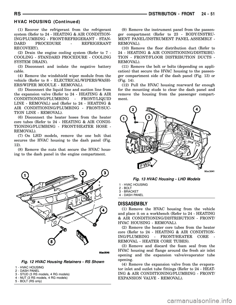
(7) On LHD models, remove the one bolt that
secures the HVAC housing to the dash panel (Fig.
12).
(8) Remove the nuts that secure the HVAC hous-
ing to the dash panel in the engine compartment.(9) Remove the instrument panel from the passen-
ger compartment (Refer to 23 - BODY/INSTRU-
MENT PANEL/INSTRUMENT PANEL ASSEMBLY -
REMOVAL).
(10) Remove the floor distribution duct (Refer to
24 - HEATING & AIR CONDITIONING/DISTRIBU-
TION - FRONT/FLOOR DISTRIBUTION DUCTS -
REMOVAL).
(11) Remove the bolt or bolts (depending on appli-
cation) that secure the HVAC housing to the passen-
ger compartment side of the dash panel (Fig. 13) or
(Fig. 14).
(12) Pull the HVAC housing rearward far enough
for the mounting studs to clear the dash panel and
remove the housing from the passenger compart-
ment.
DISSASEMBLY
(1) Remove the HVAC housing from the vehicle
and place it on a workbench (Refer to 24 - HEATING
& AIR CONDITIONING/DISTRIBUTION - FRONT/
HVAC HOUSING - REMOVAL).
(2) Remove the heater core tubes from the heater
core (Refer to 24 - HEATING & AIR CONDITION-
ING/PLUMBING - FRONT/HEATER CORE -
REMOVAL - HEATER CORE TUBES).
(3) Remove and discard the foam seal from the
HVAC housing seal flange around the fresh air inlet
opening and the expansion valve/evaporator tube
opening.
(4) Remove the expansion valve from the evapora-
tor inlet and outlet tube fittings (Refer to 24 - HEAT-
ING & AIR CONDITIONING/PLUMBING - FRONT/
EXPANSION VALVE - REMOVAL).
Fig. 12 HVAC Housing Retainers - RS Shown
1 - HVAC HOUSING
2 - DASH PANEL
3 - STUD (3 RS models, 4 RG models)
4 - NUT (3 RS models, 4 RG models)
5 - BOLT (RS only)
Fig. 13 HVAC Housing - LHD Models
1 - HVAC HOUSING
2 - BOLT
3 - BRACKET
4 - DASH PANEL
RSDISTRIBUTION - FRONT24-51
HVAC HOUSING (Continued)
Page 2204 of 2339
(12) Remove the screw and washer from the upper
pivot of the recirculation door.
(13) Remove the twelve screws that secure the
upper HVAC housing half to the lower half.
(14) Carefully separate and remove the upper half
of the HVAC housing from the lower half. Be certain
not to lose the rubber grommet for the HVAC wire
harness evaporator temperature sensor take out.
This grommet is located on the inboard side of the
flange around the expansion valve/evaporator tube
opening, where it is captured in a notched area
between the upper and lower HVAC housing halves
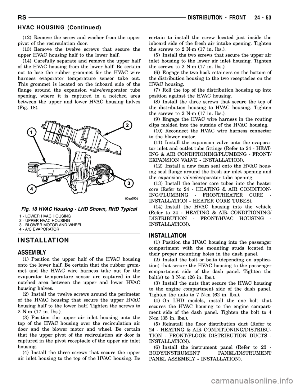
(Fig. 18).
INSTALLATION
ASSEMBLY
(1) Position the upper half of the HVAC housing
onto the lower half. Be certain that the rubber grom-
met and the HVAC wire harness take out for the
evaporator temperature sensor are captured in the
notched area between the upper and lower HVAC
housing halves.
(2) Install the twelve screws around the perimeter
of the HVAC housing that secure the upper HVAC
housing half to the lower half. Tighten the screws to
2 N´m (17 in. lbs.).
(3) Position the upper air inlet housing onto the
top of the HVAC housing over the recirculation air
door and the blower motor and wheel. Be certain
that the upper pivot of the recirculation air door is
captured in the pivot receptacle of the upper air inlet
housing.
(4) Install the three screws that secure the upper
air inlet housing to the top of the HVAC housing. Becertain to install the screw located just inside the
inboard side of the fresh air intake opening. Tighten
the screws to 2 N´m (17 in. lbs.).
(5) Install the two screws that secure the upper air
inlet housing to the lower air inlet housing. Tighten
the screws to 2 N´m (17 in. lbs.).
(6) Engage the two hook retainers on the bottom of
the distribution housing to the two receptacles on the
HVAC housing.
(7) Roll the top of the distribution housing up into
position against the HVAC housing.
(8) Install the three screws that secure the top of
the distribution housing to HVAC housing. Tighten
the screws to 2 N´m (17 in. lbs.).
(9) Engage the HVAC wire harness in the routing
clips molded into the outside of the HVAC housing.
(10) Reconnect the HVAC wire harness connector
to the blower motor.
(11) Install the expansion valve onto the evapora-
tor inlet and outlet tube fittings (Refer to 24 - HEAT-
ING & AIR CONDITIONING/PLUMBING - FRONT/
EXPANSION VALVE - INSTALLATION).
(12) Install a new foam seal onto the HVAC hous-
ing seal flange around the fresh air inlet opening and
the expansion valve/evaporator tube opening.
(13) Install the heater core tubes into the heater
core (Refer to 24 - HEATING & AIR CONDITION-
ING/PLUMBING - FRONT/HEATER CORE -
INSTALLATION - HEATER CORE TUBES).
(14) Install the HVAC housing into the vehicle
(Refer to 24 - HEATING & AIR CONDITIONING/
DISTRIBUTION - FRONT/HVAC HOUSING -
INSTALLATION).
INSTALLATION
(1) Position the HVAC housing into the passenger
compartment with the mounting studs located in
their proper mounting holes in the dash panel.
(2) Install the bolt or bolts (depending on applica-
tion) that secure the HVAC housing to the passenger
compartment side of the dash panel. Tighten the
bolt(s) to 3 N´m (26 in. lbs.).
(3) Install the nuts that secure the HVAC housing
to the engine compartment side of the dash panel.
Tighten the nuts to 7 N´m (62 in. lbs.).
(4) On LHD models, install the one bolt that
secures the HVAC housing to the engine compart-
ment side of the dash panel. Tighten the bolt to 4
N´m (35 in. lbs.).
(5) Reinstall the floor distribution duct (Refer to
24 - HEATING & AIR CONDITIONING/DISTRIBU-
TION - FRONT/FLOOR DISTRIBUTION DUCTS -
INSTALLATION).
(6) Install the instrument panel (Refer to 23 -
BODY/INSTRUMENT PANEL/INSTRUMENT
PANEL ASSEMBLY - INSTALLATION).
Fig. 18 HVAC Housing - LHD Shown, RHD Typical
1 - LOWER HVAC HOUSING
2 - UPPER HVAC HOUSING
3 - BLOWER MOTOR AND WHEEL
4 - A/C EVAPORATOR
RSDISTRIBUTION - FRONT24-53
HVAC HOUSING (Continued)
Page 2205 of 2339
(7) Reconnect the heater hoses to the heater core
tubes (Refer to 24 - HEATING & AIR CONDITION-
ING/PLUMBING - FRONT/HEATER HOSE -
INSTALLATION).
(8) Reconnect the suction line and liquid line to
the expansion valve (Refer to 24 - HEATING & AIR
CONDITIONING/PLUMBING - FRONT/SUCTION
LINE - INSTALLATION) and (Refer to 24 - HEAT-
ING & AIR CONDITIONING/PLUMBING - FRONT/
LIQUID LINE - INSTALLATION).
(9) Install the windshield wiper module (Refer to 8
- ELECTRICAL/WIPERS/WASHERS/WIPER MOD-
ULE - INSTALLATION).
(10) Reconnect the negative battery cable.
(11) Refill the engine cooling system (Refer to 7 -
COOLING - STANDARD PROCEDURE - COOLING
SYSTEM REFILL).
(12) Evacuate the refrigerant system (Refer to 24 -
HEATING & AIR CONDITIONING/PLUMBING -
FRONT/REFRIGERANT - STANDARD PROCE-
DURE - REFRIGERANT SYSTEM EVACUATE).
(13) Charge the refrigerant system (Refer to 24 -
HEATING & AIR CONDITIONING/PLUMBING -
FRONT/REFRIGERANT - STANDARD PROCE-
DURE - REFRIGERANT SYSTEM CHARGE).
INSTRUMENT PANEL
DEMISTER DUCTS
REMOVAL
WARNING: ON VEHICLES EQUIPPED WITH AIR-
BAGS, DISABLE THE AIRBAG SYSTEM BEFORE
ATTEMPTING ANY STEERING WHEEL, STEERING
COLUMN, OR INSTRUMENT PANEL COMPONENT
DIAGNOSIS OR SERVICE. DISCONNECT AND ISO-
LATE THE BATTERY NEGATIVE (GROUND) CABLE,
THEN WAIT TWO MINUTES FOR THE AIRBAG SYS-
TEM CAPACITOR TO DISCHARGE BEFORE PER-
FORMING FURTHER DIAGNOSIS OR SERVICE. THIS
IS THE ONLY SURE WAY TO DISABLE THE AIRBAG
SYSTEM. FAILURE TO TAKE THE PROPER PRE-
CAUTIONS COULD RESULT IN ACCIDENTAL AIR-
BAG DEPLOYMENT AND POSSIBLE PERSONAL
INJURY.(1) Disconnect and isolate the battery negative
cable.
(2) Remove the instrument panel from the vehicle.
(Refer to 23 - BODY/INSTRUMENT PANEL/IN-
STRUMENT PANEL ASSEMBLY - REMOVAL).
(3) Place the instrument panel face down on a
suitable work surface. Be certain to take the proper
precautions to protect the face of the instrument
panel from cosmetic damage.
(4) Remove the fasteners that secure the demister
ducts to the instrument panel armature.
(5) Disengage the demister ducts from the demis-
ter outlets.
(6) Remove the demister ducts from the instru-
ment panel.
INSTALLATION
WARNING: ON VEHICLES EQUIPPED WITH AIR-
BAGS, DISABLE THE AIRBAG SYSTEM BEFORE
ATTEMPTING ANY STEERING WHEEL, STEERING
COLUMN, OR INSTRUMENT PANEL COMPONENT
DIAGNOSIS OR SERVICE. DISCONNECT AND ISO-
LATE THE BATTERY NEGATIVE (GROUND) CABLE,
THEN WAIT TWO MINUTES FOR THE AIRBAG SYS-
TEM CAPACITOR TO DISCHARGE BEFORE PER-
FORMING FURTHER DIAGNOSIS OR SERVICE. THIS
IS THE ONLY SURE WAY TO DISABLE THE AIRBAG
SYSTEM. FAILURE TO TAKE THE PROPER PRE-
CAUTIONS COULD RESULT IN ACCIDENTAL AIR-
BAG DEPLOYMENT AND POSSIBLE PERSONAL
INJURY.
(1) Position the demister ducts to the instrument
panel.
(2) Engage the demister ducts to the demister out-
lets.
(3) Install the fasteners that secure the demister
ducts to the instrument panel armature.
(4) Reinstall the instrument panel into the vehicle.
(Refer to 23 - BODY/INSTRUMENT PANEL/IN-
STRUMENT PANEL ASSEMBLY - INSTALLA-
TION).
(5) Reconnect the battery negative cable.
24 - 54 DISTRIBUTION - FRONTRS
HVAC HOUSING (Continued)
Page 2206 of 2339
INSTRUMENT PANEL DUCTS
REMOVAL
WARNING: ON VEHICLES EQUIPPED WITH AIR-
BAGS, DISABLE THE AIRBAG SYSTEM BEFORE
ATTEMPTING ANY STEERING WHEEL, STEERING
COLUMN, OR INSTRUMENT PANEL COMPONENT
DIAGNOSIS OR SERVICE. DISCONNECT AND ISO-
LATE THE BATTERY NEGATIVE (GROUND) CABLE,
THEN WAIT TWO MINUTES FOR THE AIRBAG SYS-
TEM CAPACITOR TO DISCHARGE BEFORE PER-
FORMING FURTHER DIAGNOSIS OR SERVICE. THIS
IS THE ONLY SURE WAY TO DISABLE THE AIRBAG
SYSTEM. FAILURE TO TAKE THE PROPER PRE-
CAUTIONS COULD RESULT IN ACCIDENTAL AIR-
BAG DEPLOYMENT AND POSSIBLE PERSONAL
INJURY.
(1) Disconnect and isolate the battery negative
cable.
(2) Remove the instrument panel from the vehicle
(Refer to 23 - BODY/INSTRUMENT PANEL/IN-
STRUMENT PANEL ASSEMBLY - REMOVAL).(3) Place the instrument panel face down on a
suitable work surface. Be certain to take the proper
precautions to protect the face of the instrument
panel from cosmetic damage.
(4) Remove the screws that secure the panel ducts
to the instrument panel armature.
(5) Disengage the panel ducts from the panel out-
lets.
(6) Remove the panel ducts from the instrument
panel.
INSTALLATION
(1) Position the panel ducts to the instrument
panel.
(2) Engage the panel ducts to the panel outlets.
(3) Install the screws that secure the panel ducts
to the instrument panel armature.
(4) Reinstall the instrument panel into the vehicle
(Refer to 23 - BODY/INSTRUMENT PANEL/IN-
STRUMENT PANEL ASSEMBLY - INSTALLA-
TION).
(5) Reconnect the battery negative cable.
RSDISTRIBUTION - FRONT24-55
Page 2219 of 2339
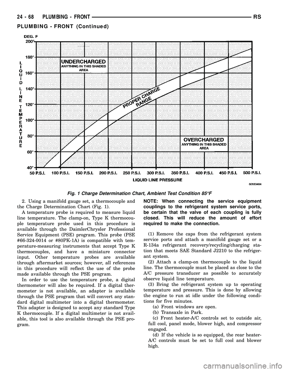
2. Using a manifold gauge set, a thermocouple and
the Charge Determination Chart (Fig. 1).
A temperature probe is required to measure liquid
line temperature. The clamp-on, Type K thermocou-
ple temperature probe used in this procedure is
available through the DaimlerChrysler Professional
Service Equipment (PSE) program. This probe (PSE
#66-324-0014 or #80PK-1A) is compatible with tem-
perature-measuring instruments that accept Type K
thermocouples, and have a miniature connector
input. Other temperature probes are available
through aftermarket sources; however, all references
in this procedure will reflect the use of the probe
made available through the PSE program.
In order to use the temperature probe, a digital
thermometer will also be required. If a digital ther-
mometer is not available, an adapter is available
through the PSE program that will convert any stan-
dard digital multimeter into a digital thermometer.
This adapter is designed to accept any standard Type
K thermocouple. If a digital multimeter is not avail-
able, this tool is also available through the PSE pro-
gram.NOTE: When connecting the service equipment
couplings to the refrigerant system service ports,
be certain that the valve of each coupling is fully
closed. This will reduce the amount of effort
required to make the connection.
(1) Remove the caps from the refrigerant system
service ports and attach a manifold gauge set or a
R-134a refrigerant recovery/recycling/charging sta-
tion that meets SAE Standard J2210 to the refriger-
ant system.
(2) Attach a clamp-on thermocouple to the liquid
line. The thermocouple must be placed as close to the
A/C pressure transducer as possible to accurately
observe liquid line temperature.
(3) Bring the refrigerant system up to operating
temperature and pressure. This is done by allowing
the engine to run at idle under the following condi-
tions for five minutes.
(a) Front windows are open.
(b) Transaxle in Park.
(c) Front heater-A/C controls set to outside air,
full cool, panel mode, blower high, and compressor
engaged.
(d) If the vehicle is so equipped, the rear heater-
A/C controls must be set to full cool and blower
high.
Fig. 1 Charge Determination Chart, Ambient Test Condition 85ÉF
24 - 68 PLUMBING - FRONTRS
PLUMBING - FRONT (Continued)
Page 2231 of 2339
INSTALLATION
(1) Position the A/C discharge line into the engine
compartment.
(2) Remove the tape or plugs from the compressor
discharge port and the discharge line fitting.
(3) Lubricate a new rubber O-ring seal with clean
refrigerant oil and install it and a new gasket onto
the discharge line fitting.
(4) Install the A/C discharge line to the A/C com-
pressor.(5) Install the nut that secures the A/C discharge
line to the A/C compressor. Tighten the nut to 23
N´m (17 ft. lbs.).
(6) Remove the tape or plugs from the condenser
inlet port and the discharge line fitting.
(7) Lubricate a new rubber O-ring seal with clean
refrigerant oil and install it and a new gasket onto
the discharge line fitting.
(8) Install the A/C discharge line to the A/C con-
denser.
(9) Install the nut that secures the A/C discharge
line to the A/C condenser. Tighten the nut to 23 N´m
(17 ft. lbs.).
(10) Position the radiator sight shield onto the
radiator closure panel crossmember.
(11) Install the five small screws that secure the
front fascia grille inserts to the radiator sight shield.
Tighten the screws to 2 N´m (17 in. lbs.).
(12) Install the two large screws that secure the
front fascia and the outboard ends of the radiator
sight shield to the radiator closure panel crossmem-
ber. Tighten the screws to 6 N´m (53 in. lbs.).
(13) Evacuate the refrigerant system (Refer to 24 -
HEATING & AIR CONDITIONING/PLUMBING -
FRONT/REFRIGERANT - STANDARD PROCE-
DURE - REFRIGERANT SYSTEM EVACUATE).
(14) Charge the refrigerant system (Refer to 24 -
HEATING & AIR CONDITIONING/PLUMBING -
FRONT/REFRIGERANT - STANDARD PROCE-
DURE - REFRIGERANT SYSTEM CHARGE).
A/C EVAPORATOR
DESCRIPTION
The A/C evaporator is located in the HVAC hous-
ing, behind the instrument panel. The evaporator is
positioned in the housing so that all air that enters
the housing must pass over the fins of the evaporator
coils before it is distributed through the system ducts
and outlets. However, air passing over the evaporator
fins will only be conditioned when the compressor is
engaged and circulating refrigerant through the
evaporator tubes.
OPERATION
Refrigerant enters the A/C evaporator from the
expansion valve as a low-temperature, low-pressure
liquid. As air flows over the fins of the evaporator,
the humidity in the air condenses on the fins, and
the heat from the air is absorbed by the refrigerant.
Heat absorption causes the refrigerant to boil and
vaporize. The refrigerant becomes a low-pressure gas
when it leaves the evaporator.
The A/C evaporator cannot be repaired and, if
faulty or damaged, it must be replaced.
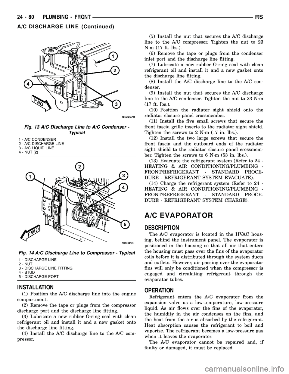
Fig. 13 A/C Discharge Line to A/C Condenser -
Typical
1 - A/C CONDENSER
2 - A/C DISCHARGE LINE
3 - A/C LIQUID LINE
4 - NUT (2)
Fig. 14 A/C Discharge Line to Compressor - Typical
1 - DISCHARGE LINE
2 - NUT
3 - DISCHARGE LINE FITTING
4 - STUD
5 - DISCHARGE PORT
24 - 80 PLUMBING - FRONTRS
A/C DISCHARGE LINE (Continued)
Page 2232 of 2339
REMOVAL
WARNING: ON VEHICLES EQUIPPED WITH AIR-
BAGS, DISABLE THE AIRBAG SYSTEM BEFORE
ATTEMPTING ANY STEERING WHEEL, STEERING
COLUMN, OR INSTRUMENT PANEL COMPONENT
DIAGNOSIS OR SERVICE. DISCONNECT AND ISO-
LATE THE BATTERY NEGATIVE (GROUND) CABLE,
THEN WAIT TWO MINUTES FOR THE AIRBAG SYS-
TEM CAPACITOR TO DISCHARGE BEFORE PER-
FORMING FURTHER DIAGNOSIS OR SERVICE. THIS
IS THE ONLY SURE WAY TO DISABLE THE AIRBAG
SYSTEM. FAILURE TO TAKE THE PROPER PRE-
CAUTIONS COULD RESULT IN ACCIDENTAL AIR-
BAG DEPLOYMENT AND POSSIBLE PERSONAL
INJURY.
(1) Remove the HVAC housing (Refer to 24 -
HEATING & AIR CONDITIONING/DISTRIBUTION/
HVAC HOUSING - REMOVAL).
(2) Disassemble the HVAC housing to access the
evaporator (Refer to 24 - HEATING & AIR CONDI-
TIONING/DISTRIBUTION/HVAC HOUSING - DIS-
ASSEMBLY).
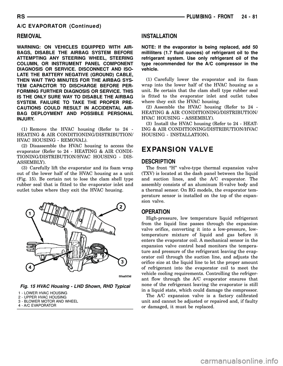
(3) Carefully lift the evaporator and its foam wrap
out of the lower half of the HVAC housing as a unit
(Fig. 15). Be certain not to lose the clam shell type
rubber seal that is fitted to the evaporator inlet and
outlet tubes where they exit the HVAC housing.
INSTALLATION
NOTE: If the evaporator is being replaced, add 50
milliliters (1.7 fluid ounces) of refrigerant oil to the
refrigerant system. Use only refrigerant oil of the
type recommended for the A/C compressor in the
vehicle.
(1) Carefully lower the evaporator and its foam
wrap into the lower half of the HVAC housing as a
unit. Be certain that the clam shell type rubber seal
is fitted to the evaporator inlet and outlet tubes
where they exit the HVAC housing.
(2) Assemble the HVAC housing (Refer to 24 -
HEATING & AIR CONDITIONING/DISTRIBUTION/
HVAC HOUSING - ASSEMBLY).
(3) Install the HVAC housing (Refer to 24 - HEAT-
ING & AIR CONDITIONING/DISTRIBUTION/HVAC
HOUSING - INSTALLATION).
EXPANSION VALVE
DESCRIPTION
The front ªHº valve-type thermal expansion valve
(TXV) is located at the dash panel between the liquid
and suction lines, and the A/C evaporator. The
assembly consists of an aluminum H-valve body and
a thermal sensor. On RG models, the evaporator tem-
perature sensor is installed on the top of the expan-
sion valve.
OPERATION
High-pressure, low temperature liquid refrigerant
from the liquid line passes through the expansion
valve orifice, converting it into a low-pressure, low-
temperature mixture of liquid and gas before it
enters the evaporator coil. A mechanical sensor in the
expansion valve control head monitors the tempera-
ture and pressure of the refrigerant leaving the evap-
orator coil through the suction line, and adjusts the
orifice size at the liquid line to let the proper amount
of refrigerant into the evaporator coil to meet the
vehicle cooling requirements. Controlling the refriger-
ant flow through the A/C evaporator ensures that
none of the refrigerant leaving the evaporator is still
in a liquid state, which could damage the compressor.
The A/C expansion valve is a factory calibrated
unit and cannot be adjusted or repaired and, if faulty
or damaged, it must be replaced.
Fig. 15 HVAC Housing - LHD Shown, RHD Typical
1 - LOWER HVAC HOUSING
2 - UPPER HVAC HOUSING
3 - BLOWER MOTOR AND WHEEL
4 - A/C EVAPORATOR
RSPLUMBING - FRONT24-81
A/C EVAPORATOR (Continued)