2005 CHRYSLER CARAVAN instrument panel
[x] Cancel search: instrument panelPage 1941 of 2339
(4) Remove A-pillar trim panels.
(5) Place protective covers over instrument panel
and hood.
(6) Remove windshield molding. Using pliers, pull
outward on molding at the bottom of A-pillars.
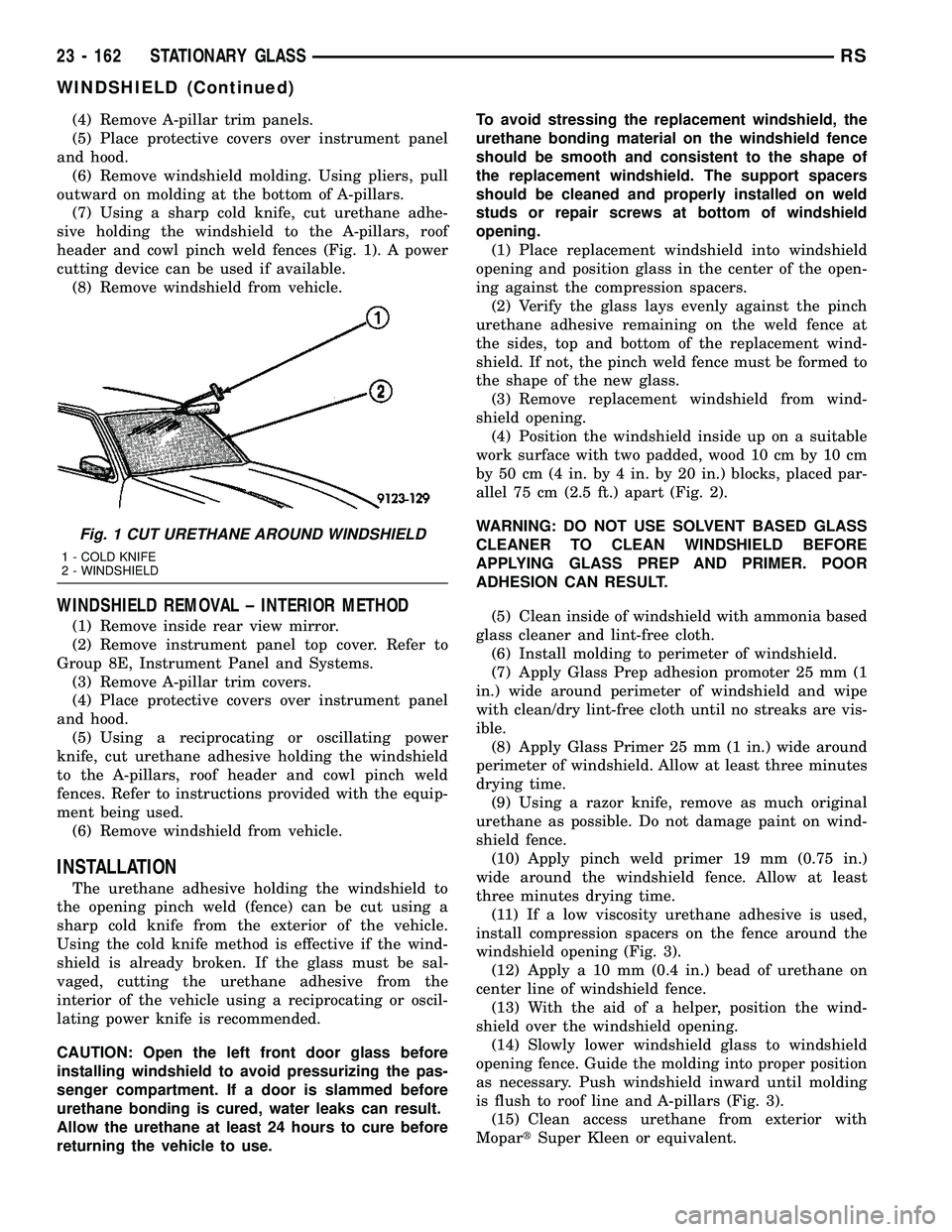
(7) Using a sharp cold knife, cut urethane adhe-
sive holding the windshield to the A-pillars, roof
header and cowl pinch weld fences (Fig. 1). A power
cutting device can be used if available.
(8) Remove windshield from vehicle.
WINDSHIELD REMOVAL ± INTERIOR METHOD
(1) Remove inside rear view mirror.
(2) Remove instrument panel top cover. Refer to
Group 8E, Instrument Panel and Systems.
(3) Remove A-pillar trim covers.
(4) Place protective covers over instrument panel
and hood.
(5) Using a reciprocating or oscillating power
knife, cut urethane adhesive holding the windshield
to the A-pillars, roof header and cowl pinch weld
fences. Refer to instructions provided with the equip-
ment being used.
(6) Remove windshield from vehicle.
INSTALLATION
The urethane adhesive holding the windshield to
the opening pinch weld (fence) can be cut using a
sharp cold knife from the exterior of the vehicle.
Using the cold knife method is effective if the wind-
shield is already broken. If the glass must be sal-
vaged, cutting the urethane adhesive from the
interior of the vehicle using a reciprocating or oscil-
lating power knife is recommended.
CAUTION: Open the left front door glass before
installing windshield to avoid pressurizing the pas-
senger compartment. If a door is slammed before
urethane bonding is cured, water leaks can result.
Allow the urethane at least 24 hours to cure before
returning the vehicle to use.To avoid stressing the replacement windshield, the
urethane bonding material on the windshield fence
should be smooth and consistent to the shape of
the replacement windshield. The support spacers
should be cleaned and properly installed on weld
studs or repair screws at bottom of windshield
opening.
(1) Place replacement windshield into windshield
opening and position glass in the center of the open-
ing against the compression spacers.
(2) Verify the glass lays evenly against the pinch
urethane adhesive remaining on the weld fence at
the sides, top and bottom of the replacement wind-
shield. If not, the pinch weld fence must be formed to
the shape of the new glass.
(3) Remove replacement windshield from wind-
shield opening.
(4) Position the windshield inside up on a suitable
work surface with two padded, wood 10 cm by 10 cm
by 50 cm (4 in. by 4 in. by 20 in.) blocks, placed par-
allel 75 cm (2.5 ft.) apart (Fig. 2).
WARNING: DO NOT USE SOLVENT BASED GLASS
CLEANER TO CLEAN WINDSHIELD BEFORE
APPLYING GLASS PREP AND PRIMER. POOR
ADHESION CAN RESULT.
(5) Clean inside of windshield with ammonia based
glass cleaner and lint-free cloth.
(6) Install molding to perimeter of windshield.
(7) Apply Glass Prep adhesion promoter 25 mm (1
in.) wide around perimeter of windshield and wipe
with clean/dry lint-free cloth until no streaks are vis-
ible.
(8) Apply Glass Primer 25 mm (1 in.) wide around
perimeter of windshield. Allow at least three minutes
drying time.
(9) Using a razor knife, remove as much original
urethane as possible. Do not damage paint on wind-
shield fence.
(10) Apply pinch weld primer 19 mm (0.75 in.)
wide around the windshield fence. Allow at least
three minutes drying time.
(11) If a low viscosity urethane adhesive is used,
install compression spacers on the fence around the
windshield opening (Fig. 3).
(12) Apply a 10 mm (0.4 in.) bead of urethane on
center line of windshield fence.
(13) With the aid of a helper, position the wind-
shield over the windshield opening.
(14) Slowly lower windshield glass to windshield
opening fence. Guide the molding into proper position
as necessary. Push windshield inward until molding
is flush to roof line and A-pillars (Fig. 3).
(15) Clean access urethane from exterior with
MopartSuper Kleen or equivalent.
Fig. 1 CUT URETHANE AROUND WINDSHIELD
1 - COLD KNIFE
2 - WINDSHIELD
23 - 162 STATIONARY GLASSRS
WINDSHIELD (Continued)
Page 2014 of 2339
DESCRIPTION FIGURE
FUEL TANK SUPPORT AND TIRE STOWAGE - SHORT WHEEL BASE ONLY 119
INNER SIDE SILLS - SHORT WHEEL BASE ONLY 120
REAR SEAT REINFORCEMENTS - SHORT WHEEL BASE ONLY 121
CENTER CONSOLE REINFORCEMENT - SHORT WHEEL BASE ONLY 122
WHEELHOUSES - SHORT WHEEL BASE ONLY 123
FRONT SEAT CROSS MEMBER - SHORT WHEELBASE, ALL WHEEL DRIVE ONLY 124
FLOOR PAN SIDE RAIL - LONG WHEEL BASE ONLY 125
INNER BODY SIDE SILL REINFORCEMENTS 126
TOE BOARD CROSS MEMBER 127
FRONT SIDE RAIL - SHORT WHEEL BASE ONLY 128
DASH PANEL REINFORCEMENT 129
LOWER COWL PLENUM 130
UPPER COWL PLENUM SUPPORT 131
UPPER DASH PANEL 132
COWL SIDE PANELS 133
INSTRUMENT PANEL ATTACHMENT TAPPING PLATES 134
INSTRUMENT PANEL, DASH PANEL, ACM MODULE AND ACCELERATOR PEDAL 135
STRUT TOWER BRACKET AND COWL PLENUM 136
FRONT SIDE RAILS TO LOWER DASH PANEL 137
INNER BODY SIDE SILL TO LOWER DASH PANEL 138
FRONT HINGE TAPPING PLATE 139
FRONT HINGE PILLAR 140
INNER WINDSHIELD FRAME 141
WINDSHIELD FRAME 142
FENDER BRACKET 143
INNER B-PILLAR 144
STRIKER LATCH AND TAPPING PLATES 145
RIGHT REAR INNER QUARTER PANEL - LONG WHEEL BASE ONLY 146
RIGHT REAR INNER QUARTER PANEL/OUTER WHEELHOUSE - LONG WHEEL BASE
ONLY147
RIGHT REAR BODY SIDE APERTURE - LONG WHEEL BASE ONLY 148
STRIKER LATCH REINFORCEMENT - LONG WHEEL BASE ONLY 149
BELT TAPPING PLATE - LONG WHEEL BASE ONLY 150
C-PILLAR REINFORCEMENT - LONG WHEEL BASE ONLY 151
OUTER WHEELHOUSE - LONG WHEEL BASE ONLY 152
C AND D-PILLAR INNER REINFORCEMENTS - LONG WHEEL BASE ONLY 153
LEFT REAR INNER QUARTER PANEL - LONG WHEEL BASE ONLY 154
OUTER WHEELHOUSE EXTENSION - LONG WHEEL BASE ONLY 155
TAIL LAMP - LONG WHEEL BASE ONLY 156
SLIDING DOOR LATCH - LONG WHEEL BASE ONLY 157
ROOF BOW EXTENSION - LONG WHEEL BASE ONLY 158
RIGHT REAR INNER QUARTER PANEL - SHORT WHEEL BASE ONLY 159
RSBODY STRUCTURE23 - 235
WELD LOCATIONS (Continued)
Page 2016 of 2339
DESCRIPTION FIGURE
UPPER COWL PLENUM AND REINFORCEMENT - RIGHT HAND DRIVE 201
COWL SIDE PANEL AND DASH PANEL - RIGHT HAND DRIVE 202
LOWER COWL PLENUM, SUPPORT AND DASH PANEL - RIGHT HAND DRIVE 203
STEERING COLUMN REINFORCEMENT, BELT REINFORCEMENT AND DASH PANEL -
RIGHT HAND DRIVE204
INSTRUMENT PANEL TAPPING PLATE AND COWL SIDE PANEL - RIGHT HAND DRIVE 205
DASH PANEL AND BELT REINFORCEMENT - RIGHT HAND DRIVE 206
UPPER SUPPORT, UPPER REINFORCEMENT AND UPPER COWL PLENUM - RIGHT
HAND DRIVE207
UPPER SUPPORT, BRAKE PEDAL BRACKET REINFORCEMENT AND DASH PANEL -
RIGHT HAND DRIVE208
REINFORCEMENT, MOUNTING BRACKETS AND DASH PANEL - RIGHT HAND DRIVE 209
STRUT TOWER, COWL SIDE PANEL - RIGHT HAND DRIVE 210
REINFORCEMENTS, SIDE RAILS, COWL SIDE PANELS AND DASH PANEL - RIGHT
HAND DRIVE211
UPPER COWL PLENUM, GUSSETS, SIDE SHIELDS AND BODY SIDE APERTURE -
RIGHT HAND DRIVE212
SIDE GLASS ANTENNA TAPPING PLATE AND INNER BODY SIDE APERTURE - RIGHT
HAND DRIVE213
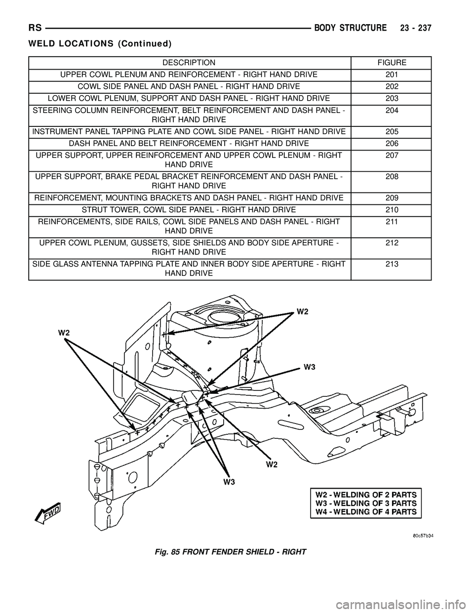
Fig. 85 FRONT FENDER SHIELD - RIGHT
RSBODY STRUCTURE23 - 237
WELD LOCATIONS (Continued)
Page 2060 of 2339
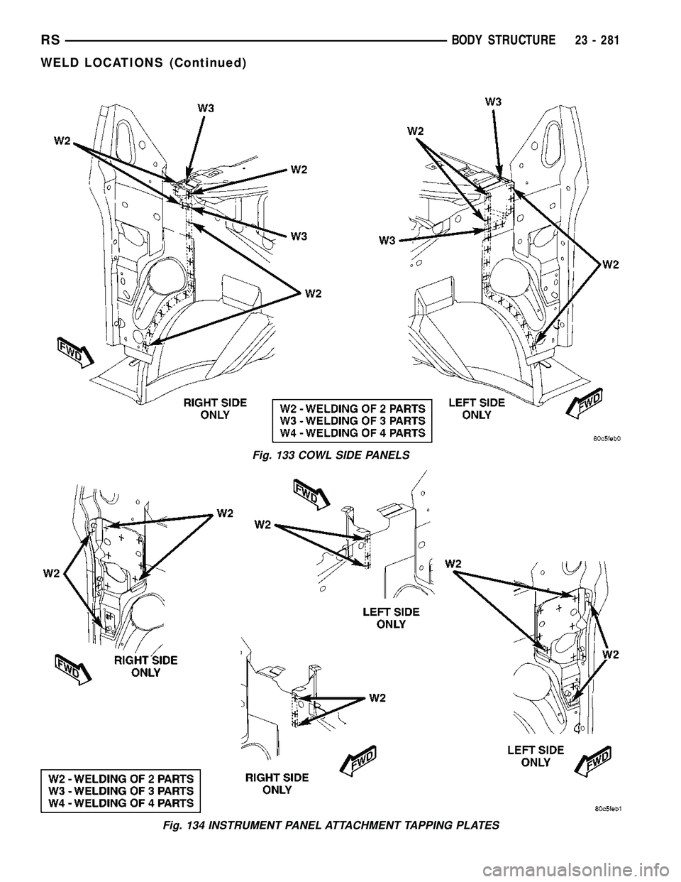
Fig. 133 COWL SIDE PANELS
Fig. 134 INSTRUMENT PANEL ATTACHMENT TAPPING PLATES
RSBODY STRUCTURE23 - 281
WELD LOCATIONS (Continued)
Page 2061 of 2339

Fig. 135 INSTRUMENT PANEL, DASH PANEL, ACM MODULE AND ACCELERATOR PEDAL
Fig. 136 STRUT TOWER BRACKET AND COWL PLENUM
23 - 282 BODY STRUCTURERS
WELD LOCATIONS (Continued)
Page 2121 of 2339
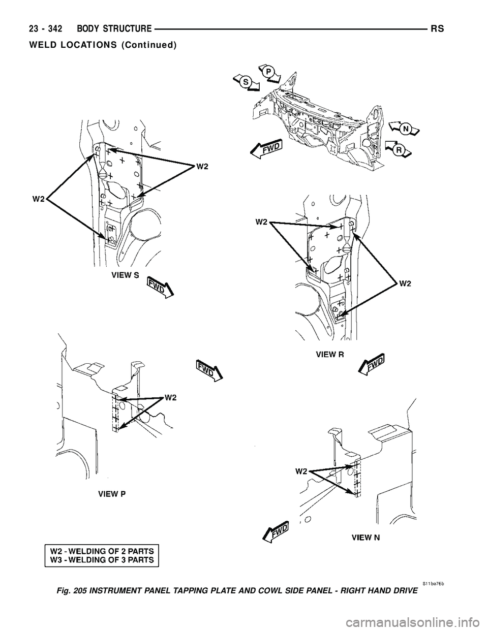
Fig. 205 INSTRUMENT PANEL TAPPING PLATE AND COWL SIDE PANEL - RIGHT HAND DRIVE
23 - 342 BODY STRUCTURERS
WELD LOCATIONS (Continued)
Page 2152 of 2339
HEATING & AIR CONDITIONING
TABLE OF CONTENTS
page page
HEATING & AIR CONDITIONING
DESCRIPTION
ENGINE COOLING SYSTEM
REQUIREMENTS.......................1
HEATER AND AIR CONDITIONER..........1
MANUAL SINGLE ZONE.................2
MANUAL DUAL ZONE...................2
MANUAL THREE ZONE..................2
AUTOMATIC TEMPERATURE CONTROL....3
OPERATION
HEATER AND AIR CONDITIONER..........4
MANUAL SINGLE ZONE.................4
MANUAL DUAL ZONE...................5
MANUAL THREE ZONE..................5AUTOMATIC TEMPERATURE CONTROL....5
DIAGNOSIS AND TESTING
A/C COOL DOWN TEST.................6
A/C PERFORMANCE TEST...............7
HEATER PERFORMANCE TEST..........10
SPECIFICATIONS
A/C SYSTEM.........................11
CONTROLS - FRONT.....................13
CONTROLS - REAR......................33
DISTRIBUTION - FRONT...................42
DISTRIBUTION - REAR....................56
PLUMBING - FRONT.....................64
PLUMBING - REAR......................98
CABIN HEATER........................113
HEATING & AIR
CONDITIONING
DESCRIPTION
ENGINE COOLING SYSTEM REQUIREMENTS
To maintain the performance level of the heating,
ventilation and air conditioning (HVAC) system, the
engine cooling system must be properly maintained.
The use of a bug screen is not recommended. Any
obstructions in front of the radiator or condenser will
reduce the performance of the air conditioning and
engine cooling systems.
The engine cooling system includes the radiator,
thermostat, radiator hoses and the engine coolant
pump. Refer to Cooling for more information before
opening or attempting any service to the engine cool-
ing system.
HEATER AND AIR CONDITIONER
A manually controlled single zone type heating-air
conditioning system, manually controlled dual zone
type heating-air conditioning system, manually con-
trolled three zone type heating-air conditioning sys-
tem or an automatic controlled three zone type
heating-air conditioning system is available on this
model.
All vehicles are equipped with a common heater,
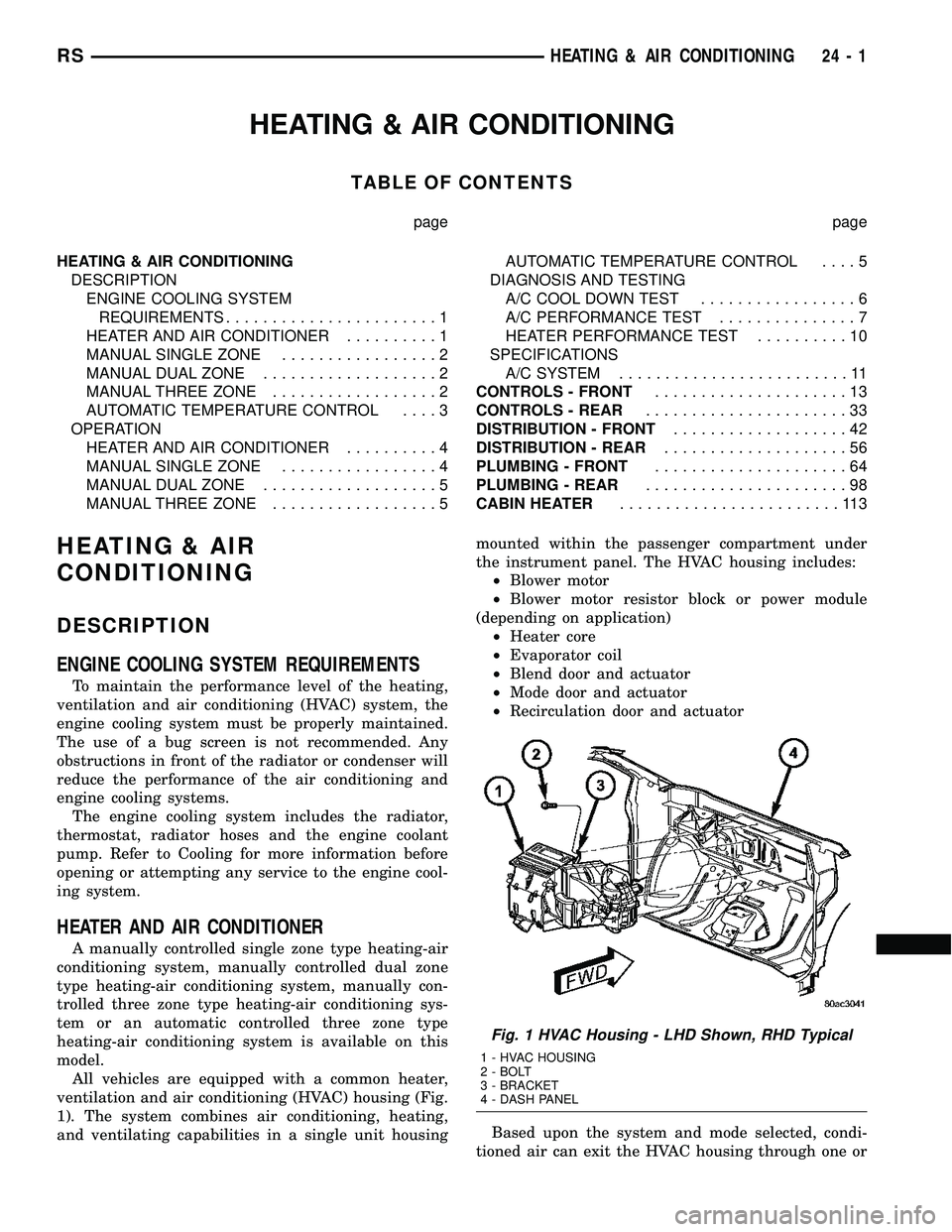
ventilation and air conditioning (HVAC) housing (Fig.
1). The system combines air conditioning, heating,
and ventilating capabilities in a single unit housingmounted within the passenger compartment under
the instrument panel. The HVAC housing includes:
²Blower motor
²Blower motor resistor block or power module
(depending on application)
²Heater core
²Evaporator coil
²Blend door and actuator
²Mode door and actuator
²Recirculation door and actuator
Based upon the system and mode selected, condi-
tioned air can exit the HVAC housing through one or
Fig. 1 HVAC Housing - LHD Shown, RHD Typical
1 - HVAC HOUSING
2 - BOLT
3 - BRACKET
4 - DASH PANEL
RSHEATING & AIR CONDITIONING24-1
Page 2153 of 2339
a combination of the three main housing outlets:
defrost, panel or floor. The defrost and panel outlets
are located on the top of the housing and the floor
outlet is located on the bottom of the housing. Once
the conditioned air exits the unit housing, it is fur-
ther directed through molded plastic ducts to the var-
ious outlets in the vehicle interior. These outlets and
their locations are as follows:
²Defroster Outlet- A single large defroster out-
let is located in the center of the instrument panel
top cover, near the base of the windshield.
²Side Window Demister Outlets- There are
two side window demister outlets, one is located at
each outboard end of the instrument panel, near the
A-pillars.
²Panel Outlets- There are five panel outlets in
the instrument panel, one located near each outboard
end of the instrument panel facing the rear of the
vehicle and three located near the top of the instru-
ment panel center bezel.
²Front Floor Outlets- There are two front floor
outlets, one located above each side of the center of
the floor panel near the dash panel.
MANUAL SINGLE ZONE
The manual single zone heating and A/C system
allows one temperature setting for the entire vehicle.
The full range of temperatures that the system can
produce are available by rotating the temperature
control located on the A/C-heater control.
The A/C-heater control and integral computer is
located in the instrument panel and contains:
²a rear window defogger on/off switch. Contains
an LED that illuminates to show when the function
is operational.
²an air recirculation on/off switch. The Recircu-
late button contains an LED that illuminates to show
when the function is in operation.
²an air conditioning on/off switch. The Snowflake
button contains an LED that illuminates to shown
when the function is in operation.
²a rotary knob for fan speed selection and turn-
ing the heater-A/C system off.
²a rotary knob for temperature control of the dis-
charged air.
²a rotary knob for mode control.
MANUAL DUAL ZONE
The manual dual zone heating and A/C system
allows completely independent side-to-side tempera-
ture control of the discharge air.
The A/C-heater control and integral computer is
located in the instrument panel and contains:
²a rear window defogger on/off switch. Contains
an LED that illuminates to show when the function
is operational.²slide controls for completely independent side-to-
side temperature control of the discharged air. The
full range of temperature that the system can pro-
duce in any mode is available on either side of the
vehicle by independently positioning the slide con-
trols on the instrument panel.
²an air recirculation on/off switch. The Recircu-
late button contains an LED that illuminates to show
when the function is in operation.
²an air conditioning on/off switch. The Snowflake
button contains an LED that illuminates to shown
when the function is in operation.
²a rotary knob for fan speed selection and turn-
ing the heater-A/C system off.
²a rotary knob for mode control.
MANUAL THREE ZONE
The fully adjustable manual three zone front and
rear heating and A/C system allows intermediate
seat passengers the ability to regulate air tempera-
ture as well as fan speed and provides floor outlets to
the rear of the right sliding door and overhead out-
lets at each rear outboard seating position. Primary
control for the rear blower is on the front A/C-heater
control. All controls are identified by ISO graphic
symbols.
FRONT CONTROL PANEL
The front A/C-heater control and integral computer
mounted in the instrument panel contains:
²a rear window defogger on/off switch.
²slide controls for completely independent side-to-
side temperature control of the discharge air. The full
range of temperature that the system can produce in
any mode is available on either side of the vehicle by
independently positioning the slide controls on the
instrument panel.
²an air recirculation button. The Recirculate but-
ton contains an LED that illuminates to show when
the function is in operation.
²an air conditioning button that allows the com-
pressor to be turned on/off. The Snowflake button
contains an LED that illuminates to shown when the
function is in operation.
²a rotary knob for front fan speed selection and
turning the heater-A/C system off.
²a rotary knob for rear fan speed selection.
²a rotary knob for mode control.
REAR CONTROL PANEL
The rear A/C-heater control centrally mounted in
the headliner allows intermediate seat passengers to
adjust rear air distribution, temperature and blower
motor speed when the center knob on the front A/C-
heater control is set to the Rear position. The rear
A/C-heater control contains:
24 - 2 HEATING & AIR CONDITIONINGRS
HEATING & AIR CONDITIONING (Continued)