2005 CHRYSLER CARAVAN torque
[x] Cancel search: torquePage 1303 of 2339
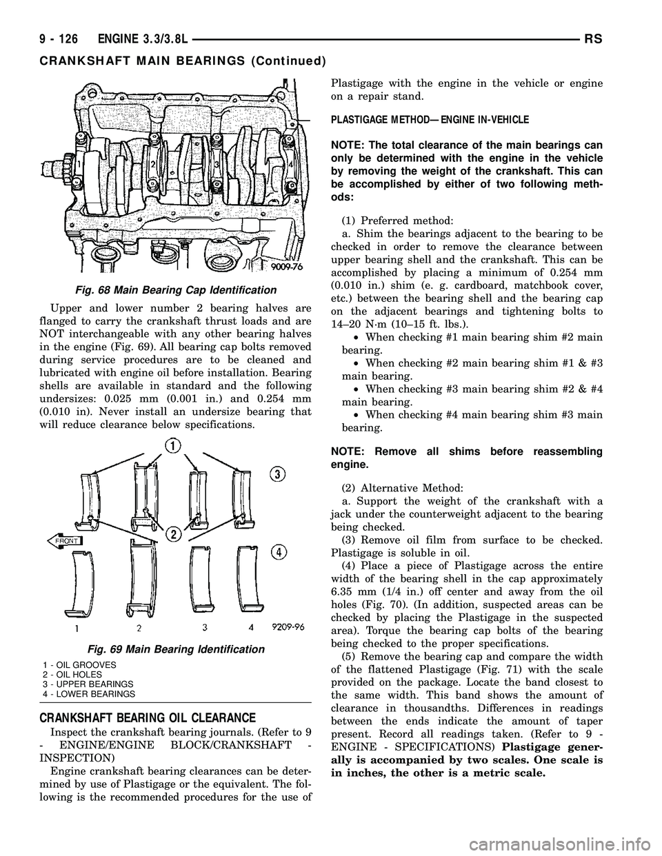
Upper and lower number 2 bearing halves are
flanged to carry the crankshaft thrust loads and are
NOT interchangeable with any other bearing halves
in the engine (Fig. 69). All bearing cap bolts removed
during service procedures are to be cleaned and
lubricated with engine oil before installation. Bearing
shells are available in standard and the following
undersizes: 0.025 mm (0.001 in.) and 0.254 mm
(0.010 in). Never install an undersize bearing that
will reduce clearance below specifications.
CRANKSHAFT BEARING OIL CLEARANCE
Inspect the crankshaft bearing journals. (Refer to 9
- ENGINE/ENGINE BLOCK/CRANKSHAFT -
INSPECTION)
Engine crankshaft bearing clearances can be deter-
mined by use of Plastigage or the equivalent. The fol-
lowing is the recommended procedures for the use ofPlastigage with the engine in the vehicle or engine
on a repair stand.
PLASTIGAGE METHODÐENGINE IN-VEHICLE
NOTE: The total clearance of the main bearings can
only be determined with the engine in the vehicle
by removing the weight of the crankshaft. This can
be accomplished by either of two following meth-
ods:
(1) Preferred method:
a. Shim the bearings adjacent to the bearing to be
checked in order to remove the clearance between
upper bearing shell and the crankshaft. This can be
accomplished by placing a minimum of 0.254 mm
(0.010 in.) shim (e. g. cardboard, matchbook cover,
etc.) between the bearing shell and the bearing cap
on the adjacent bearings and tightening bolts to
14±20 N´m (10±15 ft. lbs.).
²When checking #1 main bearing shim #2 main
bearing.
²When checking #2 main bearing shim #1 & #3
main bearing.
²When checking #3 main bearing shim #2 & #4
main bearing.
²When checking #4 main bearing shim #3 main
bearing.
NOTE: Remove all shims before reassembling
engine.
(2) Alternative Method:
a. Support the weight of the crankshaft with a
jack under the counterweight adjacent to the bearing
being checked.
(3) Remove oil film from surface to be checked.
Plastigage is soluble in oil.
(4) Place a piece of Plastigage across the entire
width of the bearing shell in the cap approximately
6.35 mm (1/4 in.) off center and away from the oil
holes (Fig. 70). (In addition, suspected areas can be
checked by placing the Plastigage in the suspected
area). Torque the bearing cap bolts of the bearing
being checked to the proper specifications.
(5) Remove the bearing cap and compare the width
of the flattened Plastigage (Fig. 71) with the scale
provided on the package. Locate the band closest to
the same width. This band shows the amount of
clearance in thousandths. Differences in readings
between the ends indicate the amount of taper
present. Record all readings taken. (Refer to 9 -
ENGINE - SPECIFICATIONS)Plastigage gener-
ally is accompanied by two scales. One scale is
in inches, the other is a metric scale.
Fig. 68 Main Bearing Cap Identification
Fig. 69 Main Bearing Identification
1 - OIL GROOVES
2 - OIL HOLES
3 - UPPER BEARINGS
4 - LOWER BEARINGS
9 - 126 ENGINE 3.3/3.8LRS
CRANKSHAFT MAIN BEARINGS (Continued)
Page 1304 of 2339
NOTE: Plastigage is available in a variety of clear-
ance ranges. Use the most appropriate range for
the specifications you are checking.
PLASTIGAGE METHODÐENGINE OUT-OF-VEHICLE
(1) With engine in the inverted position (crank-
shaft up) and mounted on a repair stand, remove
main journal cap.
(2) Remove oil from journal and bearing shell.
(3) Cut Plastigage to same length as width of the
bearing and place it in parallel with the journal axis
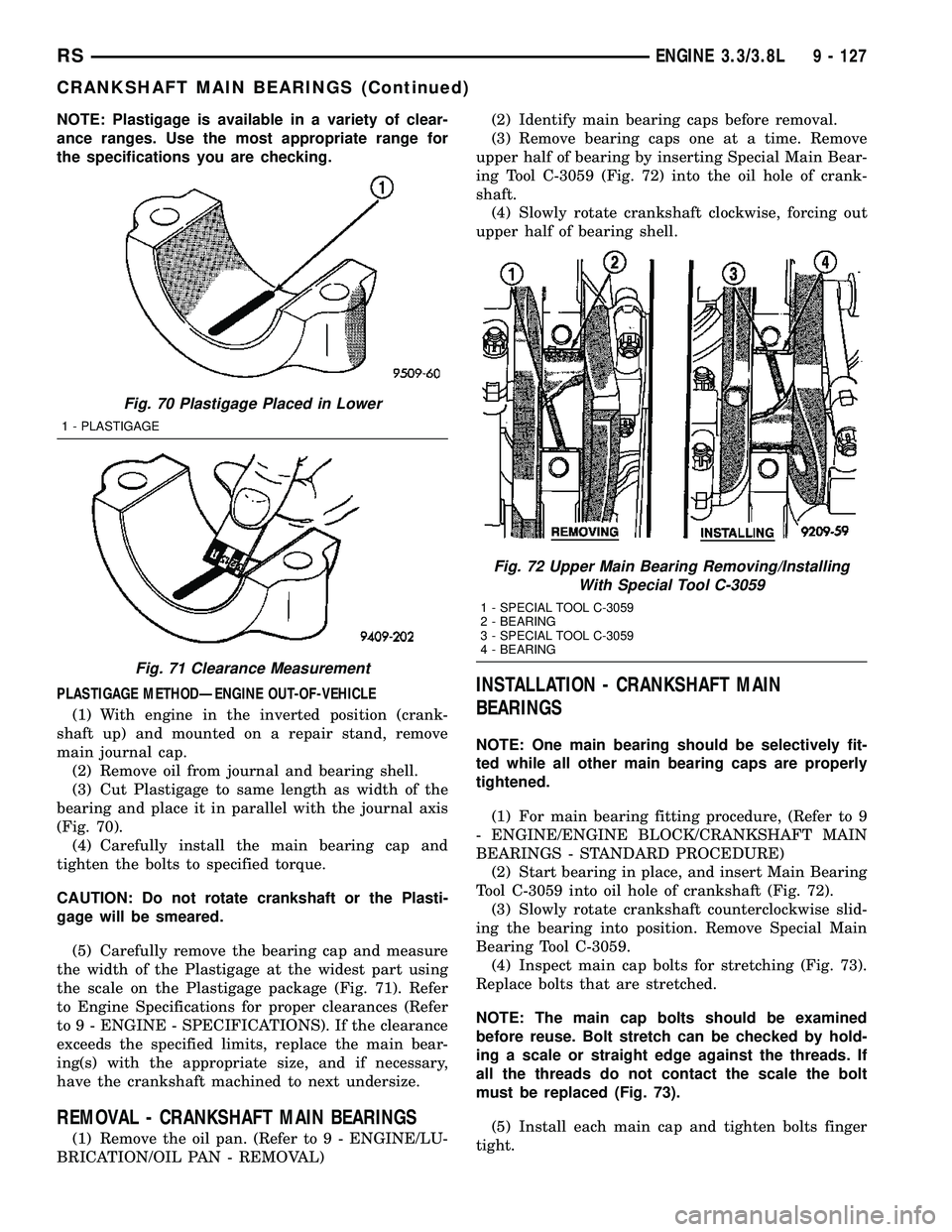
(Fig. 70).
(4) Carefully install the main bearing cap and
tighten the bolts to specified torque.
CAUTION: Do not rotate crankshaft or the Plasti-
gage will be smeared.
(5) Carefully remove the bearing cap and measure
the width of the Plastigage at the widest part using
the scale on the Plastigage package (Fig. 71). Refer
to Engine Specifications for proper clearances (Refer
to 9 - ENGINE - SPECIFICATIONS). If the clearance
exceeds the specified limits, replace the main bear-
ing(s) with the appropriate size, and if necessary,
have the crankshaft machined to next undersize.
REMOVAL - CRANKSHAFT MAIN BEARINGS
(1) Remove the oil pan. (Refer to 9 - ENGINE/LU-
BRICATION/OIL PAN - REMOVAL)(2) Identify main bearing caps before removal.
(3) Remove bearing caps one at a time. Remove
upper half of bearing by inserting Special Main Bear-
ing Tool C-3059 (Fig. 72) into the oil hole of crank-
shaft.
(4) Slowly rotate crankshaft clockwise, forcing out
upper half of bearing shell.
INSTALLATION - CRANKSHAFT MAIN
BEARINGS
NOTE: One main bearing should be selectively fit-
ted while all other main bearing caps are properly
tightened.
(1) For main bearing fitting procedure, (Refer to 9
- ENGINE/ENGINE BLOCK/CRANKSHAFT MAIN
BEARINGS - STANDARD PROCEDURE)
(2) Start bearing in place, and insert Main Bearing
Tool C-3059 into oil hole of crankshaft (Fig. 72).
(3) Slowly rotate crankshaft counterclockwise slid-
ing the bearing into position. Remove Special Main
Bearing Tool C-3059.
(4) Inspect main cap bolts for stretching (Fig. 73).
Replace bolts that are stretched.
NOTE: The main cap bolts should be examined
before reuse. Bolt stretch can be checked by hold-
ing a scale or straight edge against the threads. If
all the threads do not contact the scale the bolt
must be replaced (Fig. 73).
(5) Install each main cap and tighten bolts finger
tight.
Fig. 70 Plastigage Placed in Lower
1 - PLASTIGAGE
Fig. 71 Clearance Measurement
Fig. 72 Upper Main Bearing Removing/Installing
With Special Tool C-3059
1 - SPECIAL TOOL C-3059
2 - BEARING
3 - SPECIAL TOOL C-3059
4 - BEARING
RSENGINE 3.3/3.8L9 - 127
CRANKSHAFT MAIN BEARINGS (Continued)
Page 1309 of 2339
CRANKSHAFT REAR OIL SEAL
RETAINER
REMOVAL
(1) Remove crankshaft rear oil seal (Refer to 9 -
ENGINE/ENGINE BLOCK/CRANKSHAFT OIL
SEAL - REAR - REMOVAL).
(2) Remove oil pan (Refer to 9 - ENGINE/LUBRI-
CATION/OIL PAN - REMOVAL).
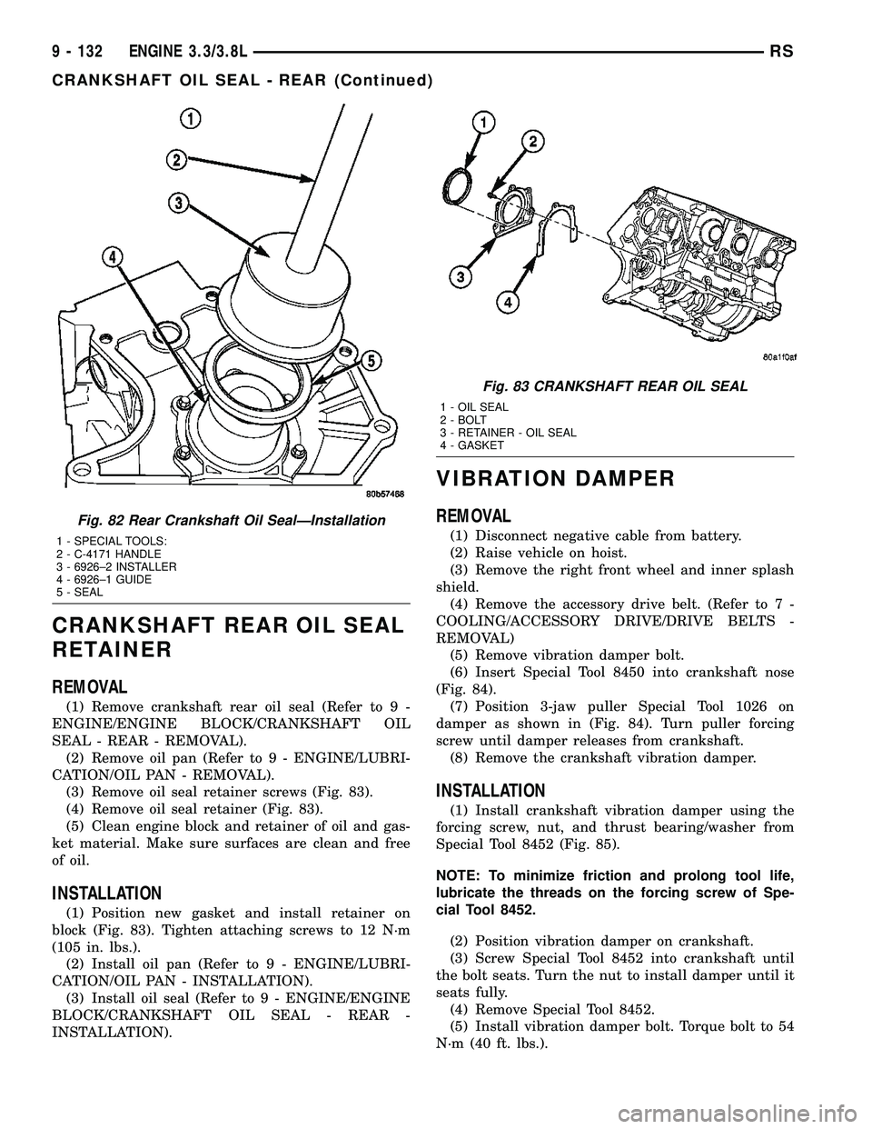
(3) Remove oil seal retainer screws (Fig. 83).
(4) Remove oil seal retainer (Fig. 83).
(5) Clean engine block and retainer of oil and gas-
ket material. Make sure surfaces are clean and free
of oil.
INSTALLATION
(1) Position new gasket and install retainer on
block (Fig. 83). Tighten attaching screws to 12 N´m
(105 in. lbs.).
(2) Install oil pan (Refer to 9 - ENGINE/LUBRI-
CATION/OIL PAN - INSTALLATION).
(3) Install oil seal (Refer to 9 - ENGINE/ENGINE
BLOCK/CRANKSHAFT OIL SEAL - REAR -
INSTALLATION).
VIBRATION DAMPER
REMOVAL
(1) Disconnect negative cable from battery.
(2) Raise vehicle on hoist.
(3) Remove the right front wheel and inner splash
shield.
(4) Remove the accessory drive belt. (Refer to 7 -
COOLING/ACCESSORY DRIVE/DRIVE BELTS -
REMOVAL)
(5) Remove vibration damper bolt.
(6) Insert Special Tool 8450 into crankshaft nose
(Fig. 84).
(7) Position 3-jaw puller Special Tool 1026 on
damper as shown in (Fig. 84). Turn puller forcing
screw until damper releases from crankshaft.
(8) Remove the crankshaft vibration damper.
INSTALLATION
(1) Install crankshaft vibration damper using the
forcing screw, nut, and thrust bearing/washer from
Special Tool 8452 (Fig. 85).
NOTE: To minimize friction and prolong tool life,
lubricate the threads on the forcing screw of Spe-
cial Tool 8452.
(2) Position vibration damper on crankshaft.
(3) Screw Special Tool 8452 into crankshaft until
the bolt seats. Turn the nut to install damper until it
seats fully.
(4) Remove Special Tool 8452.
(5) Install vibration damper bolt. Torque bolt to 54
N´m (40 ft. lbs.).
Fig. 82 Rear Crankshaft Oil SealÐInstallation
1 - SPECIAL TOOLS:
2 - C-4171 HANDLE
3 - 6926±2 INSTALLER
4 - 6926±1 GUIDE
5 - SEAL
Fig. 83 CRANKSHAFT REAR OIL SEAL
1 - OIL SEAL
2 - BOLT
3 - RETAINER - OIL SEAL
4 - GASKET
9 - 132 ENGINE 3.3/3.8LRS
CRANKSHAFT OIL SEAL - REAR (Continued)
Page 1311 of 2339
ENGINE MOUNTING
DESCRIPTION
The engine mounting system consist of four
mounts; right and a left side support the powertrain,
and a front and a rear mount control powertrain
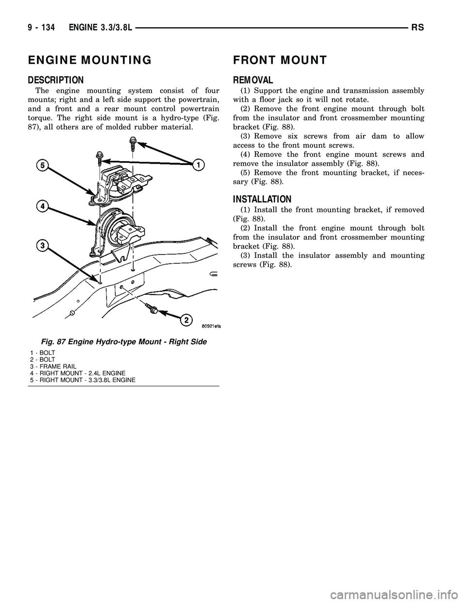
torque. The right side mount is a hydro-type (Fig.
87), all others are of molded rubber material.
FRONT MOUNT
REMOVAL
(1) Support the engine and transmission assembly
with a floor jack so it will not rotate.
(2) Remove the front engine mount through bolt
from the insulator and front crossmember mounting
bracket (Fig. 88).
(3) Remove six screws from air dam to allow
access to the front mount screws.
(4) Remove the front engine mount screws and
remove the insulator assembly (Fig. 88).
(5) Remove the front mounting bracket, if neces-
sary (Fig. 88).
INSTALLATION
(1) Install the front mounting bracket, if removed
(Fig. 88).
(2) Install the front engine mount through bolt
from the insulator and front crossmember mounting
bracket (Fig. 88).
(3) Install the insulator assembly and mounting
screws (Fig. 88).
Fig. 87 Engine Hydro-type Mount - Right Side
1 - BOLT
2 - BOLT
3 - FRAME RAIL
4 - RIGHT MOUNT - 2.4L ENGINE
5 - RIGHT MOUNT - 3.3/3.8L ENGINE
9 - 134 ENGINE 3.3/3.8LRS
Page 1321 of 2339
INSTALLATION
(1) Clean relief valve, spring and bore.
NOTE: Lubricate relief valve with clean engine oil
before installing.
(2) Install relief valve and spring into housing.
(3) Install new retainer cap until flush with seal-
ing surface.
(4) Install oil pan (Refer to 9 - ENGINE/LUBRI-
CATION/OIL PAN - INSTALLATION).
(5) Fill crankcase with proper oil to correct level.
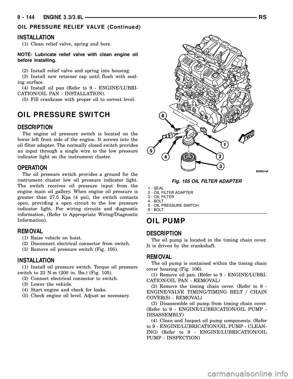
OIL PRESSURE SWITCH
DESCRIPTION
The engine oil pressure switch is located on the
lower left front side of the engine. It screws into the
oil filter adapter. The normally closed switch provides
an input through a single wire to the low pressure
indicator light on the instrument cluster.
OPERATION
The oil pressure switch provides a ground for the
instrument cluster low oil pressure indicator light.
The switch receives oil pressure input from the
engine main oil gallery. When engine oil pressure is
greater than 27.5 Kpa (4 psi), the switch contacts
open, providing a open circuit to the low pressure
indicator light. For wiring circuits and diagnostic
information, (Refer to Appropriate Wiring/Diagnostic
Information).
REMOVAL
(1) Raise vehicle on hoist.
(2) Disconnect electrical connector from switch.
(3) Remove oil pressure switch (Fig. 105).
INSTALLATION
(1) Install oil pressure switch. Torque oil pressure
switch to 23 N´m (200 in. lbs.) (Fig. 105).
(2) Connect electrical connector to switch.
(3) Lower the vehicle.
(4) Start engine and check for leaks.
(5) Check engine oil level. Adjust as necessary.
OIL PUMP
DESCRIPTION
The oil pump is located in the timing chain cover.
It is driven by the crankshaft.
REMOVAL
The oil pump is contained within the timing chain
cover housing (Fig. 106).
(1) Remove oil pan. (Refer to 9 - ENGINE/LUBRI-
CATION/OIL PAN - REMOVAL)
(2) Remove the timing chain cover. (Refer to 9 -
ENGINE/VALVE TIMING/TIMING BELT / CHAIN
COVER(S) - REMOVAL)
(3) Disassemble oil pump from timing chain cover.
(Refer to 9 - ENGINE/LUBRICATION/OIL PUMP -
DISASSEMBLY)
(4) Clean and Inspect oil pump components. (Refer
to 9 - ENGINE/LUBRICATION/OIL PUMP - CLEAN-
ING) (Refer to 9 - ENGINE/LUBRICATION/OIL
PUMP - INSPECTION)
Fig. 105 OIL FILTER ADAPTER
1 - SEAL
2 - OIL FILTER ADAPTER
3 - OIL FILTER
4 - BOLT
5 - OIL PRESSURE SWITCH
6 - BOLT
9 - 144 ENGINE 3.3/3.8LRS
OIL PRESSURE RELIEF VALVE (Continued)
Page 1324 of 2339

(2) Install timing chain cover (Refer to 9 -
ENGINE/VALVE TIMING/TIMING BELT / CHAIN
COVER(S) - INSTALLATION) and oil pan (Refer to 9
- ENGINE/VALVE TIMING/TIMING BELT / CHAIN
COVER(S) - INSTALLATION).
INTAKE MANIFOLD
DESCRIPTION
The intake system is made up of an upper and
lower intake manifold. The upper intake manifold is
made of a composite for both the 3.3L engine and for
the 3.8L engine (Fig. 118). The lower intake manifold
is common between the two engines (Fig. 122). It also
provides coolant crossover between cylinder heads
and houses the coolant thermostat (Fig. 122).
The intake manifold utilizes a compact design with
very low restriction and outstanding flow balance.
This design allows the engine to perform with a wide
torque curve while increasing higher rpm horse-
power.
If, for some reason, the molded-in vacuum ports
break, the composite manifold can be salvaged. The
vacuum ports are designed to break at the shoulder,
if overloaded. Additional material in the shoulder
area provides sufficient stock to repair. For more
information and procedure, (Refer to 9 - ENGINE/
MANIFOLDS/INTAKE MANIFOLD - STANDARD
PROCEDURE). Also, if the special screws that attach
the MAP sensor, power steering reservoir, throttle
cable bracket, and the EGR tube become stripped, an
oversized screw is available to repair the stripped-out
condition. For more information and procedure,
(Refer to 9 - ENGINE/MANIFOLDS/INTAKE MANI-
FOLD - STANDARD PROCEDURE)
DIAGNOSIS AND TESTING - INTAKE
MANIFOLD LEAKS
An intake manifold air leak is characterized by
lower than normal manifold vacuum. Also, one or
more cylinders may not be functioning.
WARNING: USE EXTREME CAUTION WHEN THE
ENGINE IS OPERATING. DO NOT STAND IN A
DIRECT LINE WITH THE FAN. DO NOT PUT YOUR
HANDS NEAR THE PULLEYS, BELTS OR THE FAN.
DO NOT WEAR LOOSE CLOTHING.
(1) Start the engine.
(2) Spray a small stream of water (Spray Bottle) at
the suspected leak area.
(3) If engine RPM'S change, the area of the sus-
pected leak has been found.
(4) Repair as required.
INTAKE MANIFOLD - UPPER
STANDARD PROCEDURE
STANDARD PROCEDURE - MANIFOLD
STRIPPED THREAD REPAIR
The composite upper intake manifold thread
bosses, if stripped out, can be repaired by utilizing a
repair screw available through Mopartparts. Repair
screws are available for the following manifold
attached components:
²MAP sensor
²Power steering reservoir
²EGR tube
²Throttle cable bracket
The repair screws require a unique tightening
torque specification from the original screw. Refer to
the following chart for specification.
DESCRIPTION TORQUE*
STRIP-OUT REPAIR SCREWS ONLY
MAP Sensor Repair
Screw4 N´m (35 in. lbs.)
Power Steering Reservoir
Repair Screw9 N´m (80 in. lbs.)
EGR Tube Attaching
Repair Screw9 N´m (80 in. lbs.)
Throttle Cable Bracket
Repair Screw9 N´m (80 in. lbs.)
*Install Slowly Using Hand Tools Only
Fig. 113 Oil Pressure Relief Valve
1 - RELIEF VALVE
2 - SPRING
3 - RETAINER CAP
RSENGINE 3.3/3.8L9 - 147
OIL PUMP (Continued)
Page 1325 of 2339
STANDARD PROCEDURE - INTAKE MANIFOLD
VACUUM PORT REPAIR
The composite intake manifold vacuum ports can
be repaired. Although, if the manifold plenum cham-
ber is damaged or cracked, the manifold must be
replaced.
To repair a broken or damaged vacuum nipple
(port) on the composite intake manifold, perform the
following procedure:
PARTS REQUIRED TOOLS REQUIRED
´ Brass Nipple ± 1/49
O.D. x 1/89pipe thread
(LDP/Speed Control Port)´ Pipe Tap ± 1/89-18
NPT
´ Drill Bit ± 11/329
´ File/Sandpaper
´ Brass Nipple ± 1/29
O.D. x 1/49pipe thread
(Brake Booster Port)´ Pipe Tap ± 1/49-18
NPT
´ Drill Bit ± 7/169
´ File/Sandpaper
NOTE: While performing this procedure, avoid get-
ting the manifold material residue into the plenum
chamber.
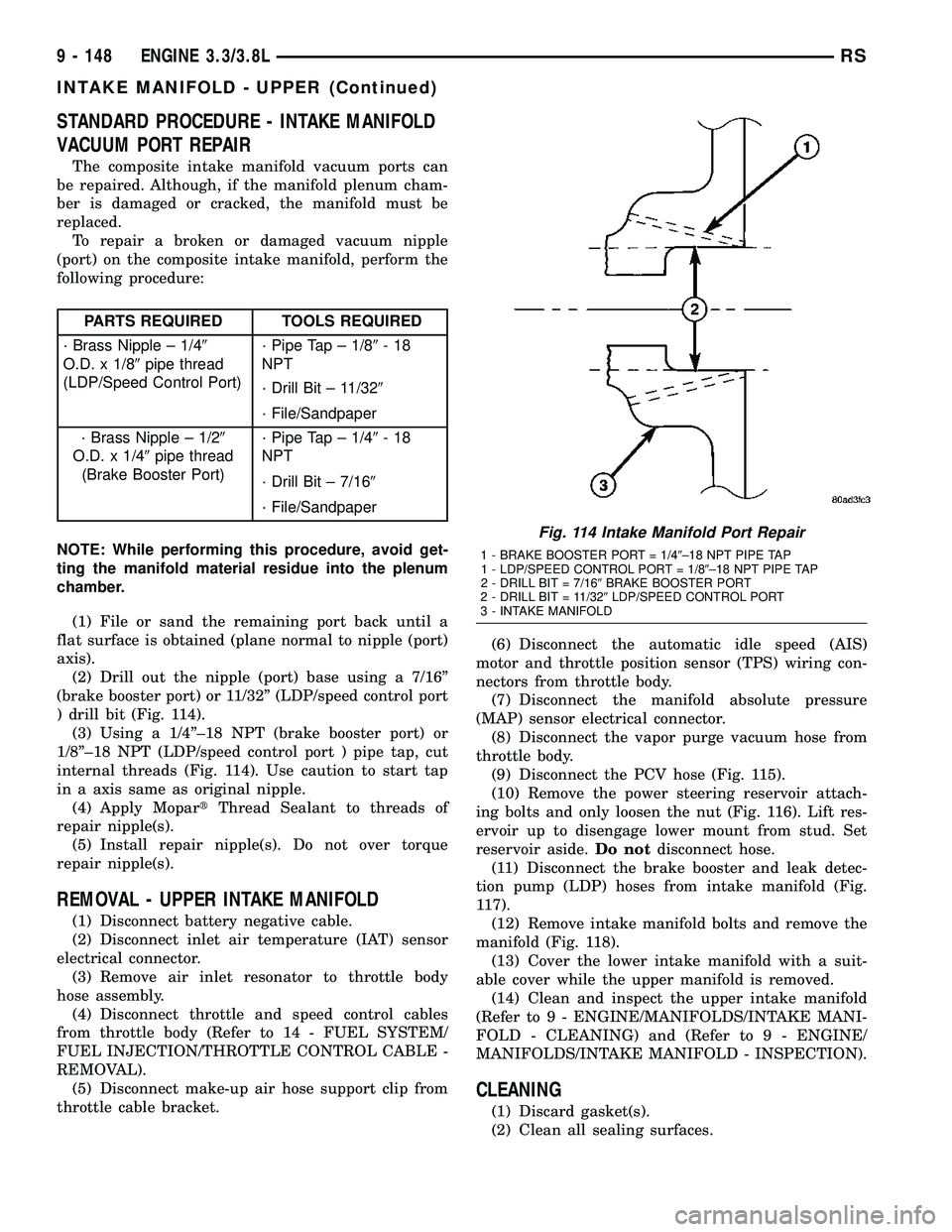
(1) File or sand the remaining port back until a
flat surface is obtained (plane normal to nipple (port)
axis).
(2) Drill out the nipple (port) base using a 7/16º
(brake booster port) or 11/32º (LDP/speed control port
) drill bit (Fig. 114).
(3) Using a 1/4º±18 NPT (brake booster port) or
1/8º±18 NPT (LDP/speed control port ) pipe tap, cut
internal threads (Fig. 114). Use caution to start tap
in a axis same as original nipple.
(4) Apply MopartThread Sealant to threads of
repair nipple(s).
(5) Install repair nipple(s). Do not over torque
repair nipple(s).
REMOVAL - UPPER INTAKE MANIFOLD
(1) Disconnect battery negative cable.
(2) Disconnect inlet air temperature (IAT) sensor
electrical connector.
(3) Remove air inlet resonator to throttle body
hose assembly.
(4) Disconnect throttle and speed control cables
from throttle body (Refer to 14 - FUEL SYSTEM/
FUEL INJECTION/THROTTLE CONTROL CABLE -
REMOVAL).
(5) Disconnect make-up air hose support clip from
throttle cable bracket.(6) Disconnect the automatic idle speed (AIS)
motor and throttle position sensor (TPS) wiring con-
nectors from throttle body.
(7) Disconnect the manifold absolute pressure
(MAP) sensor electrical connector.
(8) Disconnect the vapor purge vacuum hose from
throttle body.
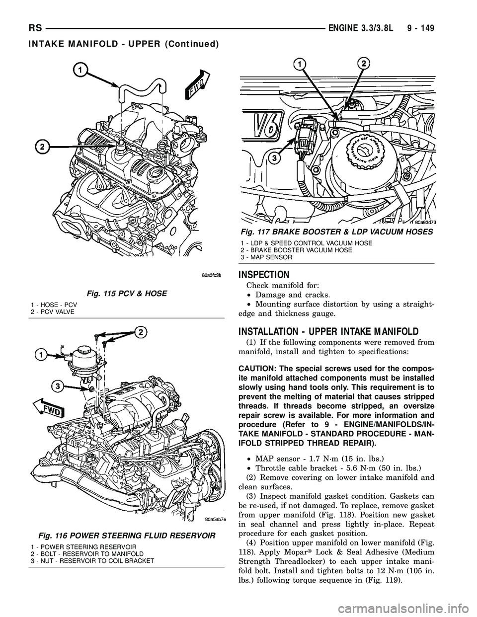
(9) Disconnect the PCV hose (Fig. 115).
(10) Remove the power steering reservoir attach-
ing bolts and only loosen the nut (Fig. 116). Lift res-
ervoir up to disengage lower mount from stud. Set
reservoir aside.Do notdisconnect hose.
(11) Disconnect the brake booster and leak detec-
tion pump (LDP) hoses from intake manifold (Fig.
117).
(12) Remove intake manifold bolts and remove the
manifold (Fig. 118).
(13) Cover the lower intake manifold with a suit-
able cover while the upper manifold is removed.
(14) Clean and inspect the upper intake manifold
(Refer to 9 - ENGINE/MANIFOLDS/INTAKE MANI-
FOLD - CLEANING) and (Refer to 9 - ENGINE/
MANIFOLDS/INTAKE MANIFOLD - INSPECTION).
CLEANING
(1) Discard gasket(s).
(2) Clean all sealing surfaces.
Fig. 114 Intake Manifold Port Repair
1 - BRAKE BOOSTER PORT = 1/49±18 NPT PIPE TAP
1 - LDP/SPEED CONTROL PORT = 1/89±18 NPT PIPE TAP
2 - DRILL BIT = 7/169BRAKE BOOSTER PORT
2 - DRILL BIT = 11/329LDP/SPEED CONTROL PORT
3 - INTAKE MANIFOLD
9 - 148 ENGINE 3.3/3.8LRS
INTAKE MANIFOLD - UPPER (Continued)
Page 1326 of 2339
INSPECTION
Check manifold for:
²Damage and cracks.
²Mounting surface distortion by using a straight-
edge and thickness gauge.
INSTALLATION - UPPER INTAKE MANIFOLD
(1) If the following components were removed from
manifold, install and tighten to specifications:
CAUTION: The special screws used for the compos-
ite manifold attached components must be installed
slowly using hand tools only. This requirement is to
prevent the melting of material that causes stripped
threads. If threads become stripped, an oversize
repair screw is available. For more information and
procedure (Refer to 9 - ENGINE/MANIFOLDS/IN-
TAKE MANIFOLD - STANDARD PROCEDURE - MAN-
IFOLD STRIPPED THREAD REPAIR).
²MAP sensor - 1.7 N´m (15 in. lbs.)
²Throttle cable bracket - 5.6 N´m (50 in. lbs.)
(2) Remove covering on lower intake manifold and
clean surfaces.
(3) Inspect manifold gasket condition. Gaskets can
be re-used, if not damaged. To replace, remove gasket
from upper manifold (Fig. 118). Position new gasket
in seal channel and press lightly in-place. Repeat
procedure for each gasket position.
(4) Position upper manifold on lower manifold (Fig.
118). Apply MopartLock & Seal Adhesive (Medium
Strength Threadlocker) to each upper intake mani-
fold bolt. Install and tighten bolts to 12 N´m (105 in.
lbs.) following torque sequence in (Fig. 119).
Fig. 115 PCV & HOSE
1 - HOSE - PCV
2 - P C V VA LV E
Fig. 116 POWER STEERING FLUID RESERVOIR
1 - POWER STEERING RESERVOIR
2 - BOLT - RESERVOIR TO MANIFOLD
3 - NUT - RESERVOIR TO COIL BRACKET
Fig. 117 BRAKE BOOSTER & LDP VACUUM HOSES
1 - LDP & SPEED CONTROL VACUUM HOSE
2 - BRAKE BOOSTER VACUUM HOSE
3 - MAP SENSOR
RSENGINE 3.3/3.8L9 - 149
INTAKE MANIFOLD - UPPER (Continued)