2005 CHRYSLER CARAVAN torque
[x] Cancel search: torquePage 1328 of 2339
WARNING: INTAKE MANIFOLD GASKET IS MADE
OF VERY THIN METAL AND MAY CAUSE PER-
SONAL INJURY, HANDLE WITH CARE.
(12) Remove intake manifold seal retainers screws
(Fig. 122). Remove intake manifold gasket.
(13) Inspect and clean manifold. (Refer to 9 -
ENGINE/MANIFOLDS/INTAKE MANIFOLD -
INSPECTION) (Refer to 9 - ENGINE/MANIFOLDS/
INTAKE MANIFOLD - CLEANING)
CLEANING
(1) Discard gasket(s).
(2) Clean all sealing surfaces.
INSPECTION
Check for:
²Damage and cracks of each section.
²Clogged water passages in end cross-overs (if
equipped).²Check for cylinder head mounting surface distor-
tion using a straightedge and thickness gauge. (Refer
to 9 - ENGINE/CYLINDER HEAD - INSPECTION)
INSTALLATION - LOWER INTAKE MANIFOLD
(1) Place a bead (approximately 1/4 in. diameter)
of MopartEngine RTV GEN II onto each of thefour
manifold to cylinder head gasket corners (Fig. 123).
(2) Carefully install the new intake manifold gas-
ket (Fig. 122). Tighten end seal retainer screws to 12
N´m (105 in. lbs.).
(3) Install lower intake manifold (Fig. 122). Install
the bolts and torque to 1 N´m (10 in. lbs.). Then
torque bolts to 22 N´m (200 in. lbs.) in sequence
shown in (Fig. 124). Then torque again to 22 N´m
(200 in. lbs.). After intake manifold is in place,
inspect to make sure seals are in place.
(4) Install the fuel injectors and rail assembly.
(Refer to 14 - FUEL SYSTEM/FUEL DELIVERY/
FUEL RAIL - INSTALLATION)
(5) Connect fuel injector electrical harness.
(6) Connect the engine coolant temperature sensor
(Fig. 121).
(7) Connect the heater supply (Fig. 121) and radi-
ator upper hoses to manifold.
(8) Connect the fuel line. (Refer to 14 - FUEL SYS-
TEM/FUEL DELIVERY/QUICK CONNECT FIT-
TING - STANDARD PROCEDURE)
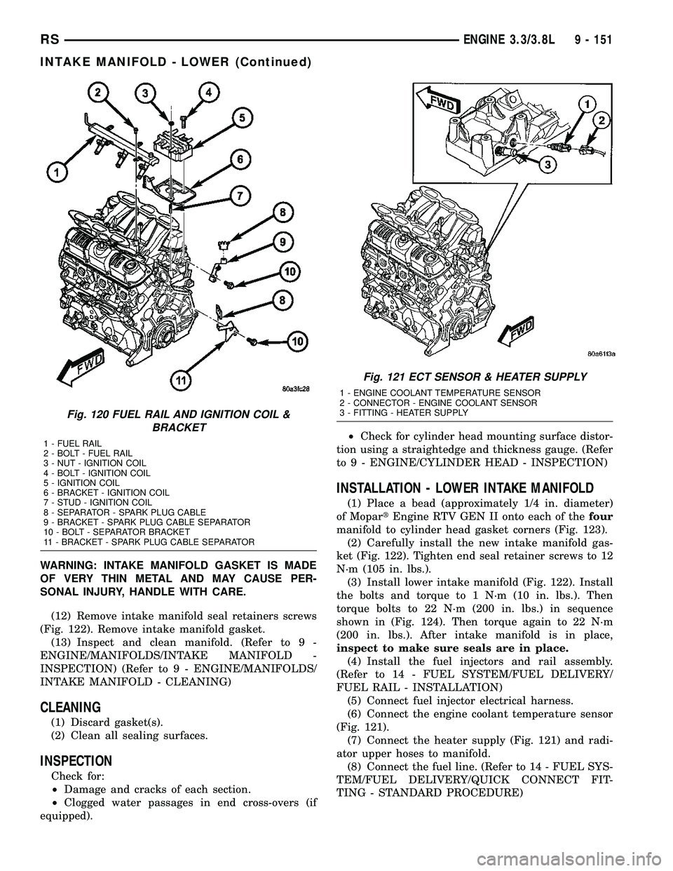
Fig. 120 FUEL RAIL AND IGNITION COIL &
BRACKET
1 - FUEL RAIL
2 - BOLT - FUEL RAIL
3 - NUT - IGNITION COIL
4 - BOLT - IGNITION COIL
5 - IGNITION COIL
6 - BRACKET - IGNITION COIL
7 - STUD - IGNITION COIL
8 - SEPARATOR - SPARK PLUG CABLE
9 - BRACKET - SPARK PLUG CABLE SEPARATOR
10 - BOLT - SEPARATOR BRACKET
11 - BRACKET - SPARK PLUG CABLE SEPARATOR
Fig. 121 ECT SENSOR & HEATER SUPPLY
1 - ENGINE COOLANT TEMPERATURE SENSOR
2 - CONNECTOR - ENGINE COOLANT SENSOR
3 - FITTING - HEATER SUPPLY
RSENGINE 3.3/3.8L9 - 151
INTAKE MANIFOLD - LOWER (Continued)
Page 1332 of 2339
INSPECTION
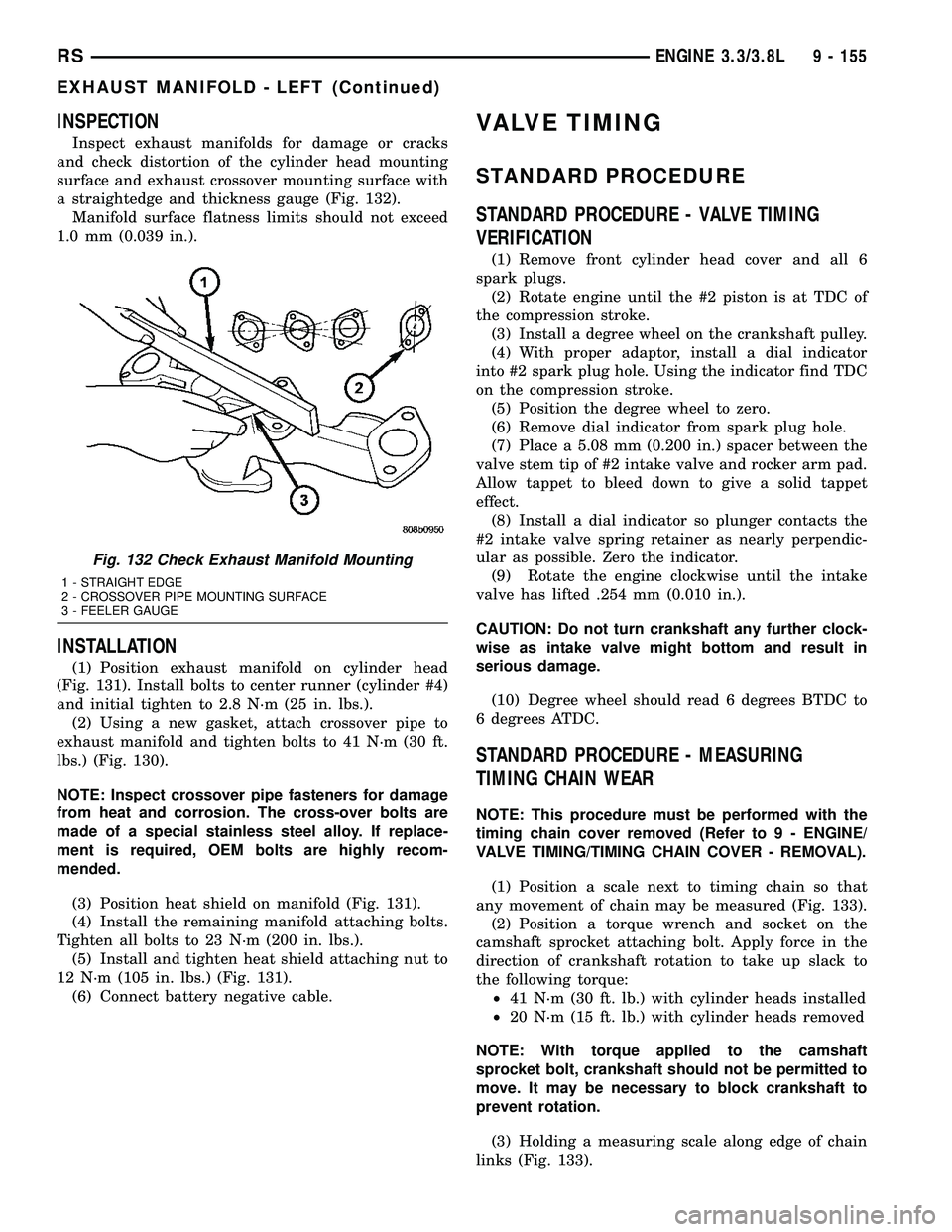
Inspect exhaust manifolds for damage or cracks
and check distortion of the cylinder head mounting
surface and exhaust crossover mounting surface with
a straightedge and thickness gauge (Fig. 132).
Manifold surface flatness limits should not exceed
1.0 mm (0.039 in.).
INSTALLATION
(1) Position exhaust manifold on cylinder head
(Fig. 131). Install bolts to center runner (cylinder #4)
and initial tighten to 2.8 N´m (25 in. lbs.).
(2) Using a new gasket, attach crossover pipe to
exhaust manifold and tighten bolts to 41 N´m (30 ft.
lbs.) (Fig. 130).
NOTE: Inspect crossover pipe fasteners for damage
from heat and corrosion. The cross-over bolts are
made of a special stainless steel alloy. If replace-
ment is required, OEM bolts are highly recom-
mended.
(3) Position heat shield on manifold (Fig. 131).
(4) Install the remaining manifold attaching bolts.
Tighten all bolts to 23 N´m (200 in. lbs.).
(5) Install and tighten heat shield attaching nut to
12 N´m (105 in. lbs.) (Fig. 131).
(6) Connect battery negative cable.
VALVE TIMING
STANDARD PROCEDURE
STANDARD PROCEDURE - VALVE TIMING
VERIFICATION
(1) Remove front cylinder head cover and all 6
spark plugs.
(2) Rotate engine until the #2 piston is at TDC of
the compression stroke.
(3) Install a degree wheel on the crankshaft pulley.
(4) With proper adaptor, install a dial indicator
into #2 spark plug hole. Using the indicator find TDC
on the compression stroke.
(5) Position the degree wheel to zero.
(6) Remove dial indicator from spark plug hole.
(7) Place a 5.08 mm (0.200 in.) spacer between the
valve stem tip of #2 intake valve and rocker arm pad.
Allow tappet to bleed down to give a solid tappet
effect.
(8) Install a dial indicator so plunger contacts the
#2 intake valve spring retainer as nearly perpendic-
ular as possible. Zero the indicator.
(9) Rotate the engine clockwise until the intake
valve has lifted .254 mm (0.010 in.).
CAUTION: Do not turn crankshaft any further clock-
wise as intake valve might bottom and result in
serious damage.
(10) Degree wheel should read 6 degrees BTDC to
6 degrees ATDC.
STANDARD PROCEDURE - MEASURING
TIMING CHAIN WEAR
NOTE: This procedure must be performed with the
timing chain cover removed (Refer to 9 - ENGINE/
VALVE TIMING/TIMING CHAIN COVER - REMOVAL).
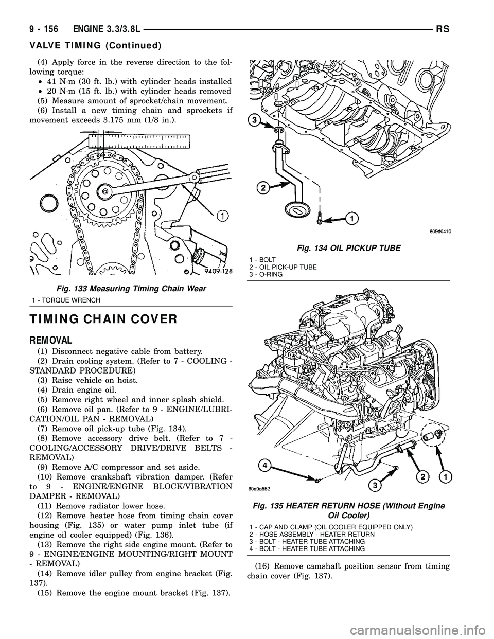
(1) Position a scale next to timing chain so that
any movement of chain may be measured (Fig. 133).
(2) Position a torque wrench and socket on the
camshaft sprocket attaching bolt. Apply force in the
direction of crankshaft rotation to take up slack to
the following torque:
²41 N´m (30 ft. lb.) with cylinder heads installed
²20 N´m (15 ft. lb.) with cylinder heads removed
NOTE: With torque applied to the camshaft
sprocket bolt, crankshaft should not be permitted to
move. It may be necessary to block crankshaft to
prevent rotation.
(3) Holding a measuring scale along edge of chain
links (Fig. 133).
Fig. 132 Check Exhaust Manifold Mounting
1 - STRAIGHT EDGE
2 - CROSSOVER PIPE MOUNTING SURFACE
3 - FEELER GAUGE
RSENGINE 3.3/3.8L9 - 155
EXHAUST MANIFOLD - LEFT (Continued)
Page 1333 of 2339
(4) Apply force in the reverse direction to the fol-
lowing torque:
²41 N´m (30 ft. lb.) with cylinder heads installed
²20 N´m (15 ft. lb.) with cylinder heads removed
(5) Measure amount of sprocket/chain movement.
(6) Install a new timing chain and sprockets if
movement exceeds 3.175 mm (1/8 in.).
TIMING CHAIN COVER
REMOVAL
(1) Disconnect negative cable from battery.
(2) Drain cooling system. (Refer to 7 - COOLING -
STANDARD PROCEDURE)
(3) Raise vehicle on hoist.
(4) Drain engine oil.
(5) Remove right wheel and inner splash shield.
(6) Remove oil pan. (Refer to 9 - ENGINE/LUBRI-
CATION/OIL PAN - REMOVAL)
(7) Remove oil pick-up tube (Fig. 134).
(8) Remove accessory drive belt. (Refer to 7 -
COOLING/ACCESSORY DRIVE/DRIVE BELTS -
REMOVAL)
(9) Remove A/C compressor and set aside.
(10) Remove crankshaft vibration damper. (Refer
to 9 - ENGINE/ENGINE BLOCK/VIBRATION
DAMPER - REMOVAL)
(11) Remove radiator lower hose.
(12) Remove heater hose from timing chain cover
housing (Fig. 135) or water pump inlet tube (if
engine oil cooler equipped) (Fig. 136).
(13) Remove the right side engine mount. (Refer to
9 - ENGINE/ENGINE MOUNTING/RIGHT MOUNT
- REMOVAL)
(14) Remove idler pulley from engine bracket (Fig.
137).
(15) Remove the engine mount bracket (Fig. 137).(16) Remove camshaft position sensor from timing
chain cover (Fig. 137).
Fig. 133 Measuring Timing Chain Wear
1 - TORQUE WRENCH
Fig. 134 OIL PICKUP TUBE
1 - BOLT
2 - OIL PICK-UP TUBE
3 - O-RING
Fig. 135 HEATER RETURN HOSE (Without Engine
Oil Cooler)
1 - CAP AND CLAMP (OIL COOLER EQUIPPED ONLY)
2 - HOSE ASSEMBLY - HEATER RETURN
3 - BOLT - HEATER TUBE ATTACHING
4 - BOLT - HEATER TUBE ATTACHING
9 - 156 ENGINE 3.3/3.8LRS
VALVE TIMING (Continued)
Page 1338 of 2339
EXHAUST SYSTEM
TABLE OF CONTENTS
page page
EXHAUST SYSTEM
DESCRIPTION..........................1
DIAGNOSIS AND TESTING
DIAGNOSIS AND TESTING - EXCESSIVE
EXHAUST SYSTEM NOISE...............2
DIAGNOSIS AND TESTING - EXHAUST
SYSTEM RESTRICTION CHECK...........2
INSPECTION...........................3
ADJUSTMENTS.........................3
SPECIFICATIONS
TORQUE.............................3
SPECIAL TOOLS
EXHAUST SYSTEM.....................4
CATALYTIC CONVERTER
DESCRIPTION..........................4
OPERATION............................4
REMOVAL.............................5INSPECTION...........................6
INSTALLATION..........................6
CROSS-OVER PIPE - 3.3/3.8L
REMOVAL.............................6
INSTALLATION..........................6
HEAT SHIELDS
DESCRIPTION..........................7
OPERATION............................7
REMOVAL.............................7
INSTALLATION..........................7
MUFFLER
REMOVAL.............................7
INSTALLATION..........................8
RESONATOR
REMOVAL.............................9
INSTALLATION..........................9
EXHAUST SYSTEM
DESCRIPTION
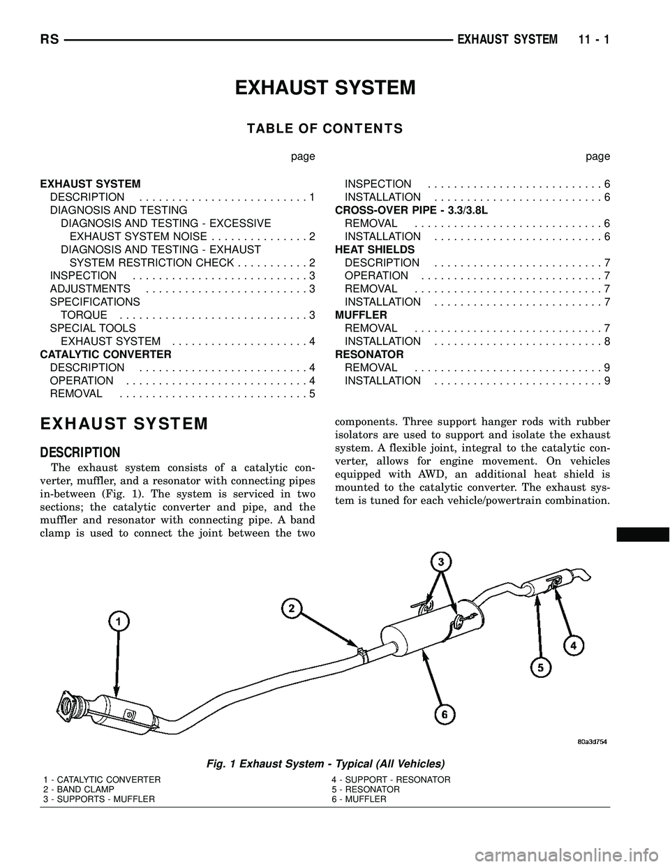
The exhaust system consists of a catalytic con-
verter, muffler, and a resonator with connecting pipes
in-between (Fig. 1). The system is serviced in two
sections; the catalytic converter and pipe, and the
muffler and resonator with connecting pipe. A band
clamp is used to connect the joint between the twocomponents. Three support hanger rods with rubber
isolators are used to support and isolate the exhaust
system. A flexible joint, integral to the catalytic con-
verter, allows for engine movement. On vehicles
equipped with AWD, an additional heat shield is
mounted to the catalytic converter. The exhaust sys-
tem is tuned for each vehicle/powertrain combination.
Fig. 1 Exhaust System - Typical (All Vehicles)
1 - CATALYTIC CONVERTER 4 - SUPPORT - RESONATOR
2 - BAND CLAMP 5 - RESONATOR
3 - SUPPORTS - MUFFLER 6 - MUFFLER
RSEXHAUST SYSTEM11-1
Page 1340 of 2339
(5) Apply the park brake and start the engine.
(6) With transmission in Park or Neutral, raise
engine speed to 2000 RPM. Monitor the pressure
readings on the DRBIIIt. Back pressure should not
exceed specified limit. Refer to specification in table
below EXHAUST BACK PRESSURE LIMITS.
(7) If pressure exceeds maximum limits, inspect
exhaust system for restricted component. For further
catalytic converter inspection procedures, (Refer to 11
- EXHAUST SYSTEM/CATALYTIC CONVERTER -
INSPECTION). Replace component(s) as necessary.
EXHAUST BACK PRESSURE LIMITS
Exhaust Back Pressure Limit (Max)
Vehicle in Park/Neutral
(no load) @2000 RPM3.45 Kpa (0.5 psi)
INSPECTION
Inspect the exhaust pipes, catalytic converters,
muffler, and resonators for cracked joints, broken
welds and corrosion damage that would result in a
leaking exhaust system. Inspect the clamps, support
brackets, and insulators for cracks and corrosion
damage.
NOTE: Slip joint band clamps are spot welded to
exhaust system. If a band clamp must be replaced,
the spot weld must be ground off.
ADJUSTMENTS
A misaligned exhaust system is usually indicated
by a vibration, rattling noise, or binding of exhaust
system components. These noises are sometimes hard
to distinguish from other chassis noises. Inspect
exhaust system for broken, damaged or loose compo-
nents such as; clamps, heat shields, isolators, and
hanger brackets. Replace or tighten as necessary. It
is important that exhaust system clearances and
alignment be maintained.
Perform the following procedures to align the
exhaust system:
(1) Loosen band clamp at catalytic converter pipe
to muffler/resonator assembly.
(2) Align the exhaust system by inserting pipe
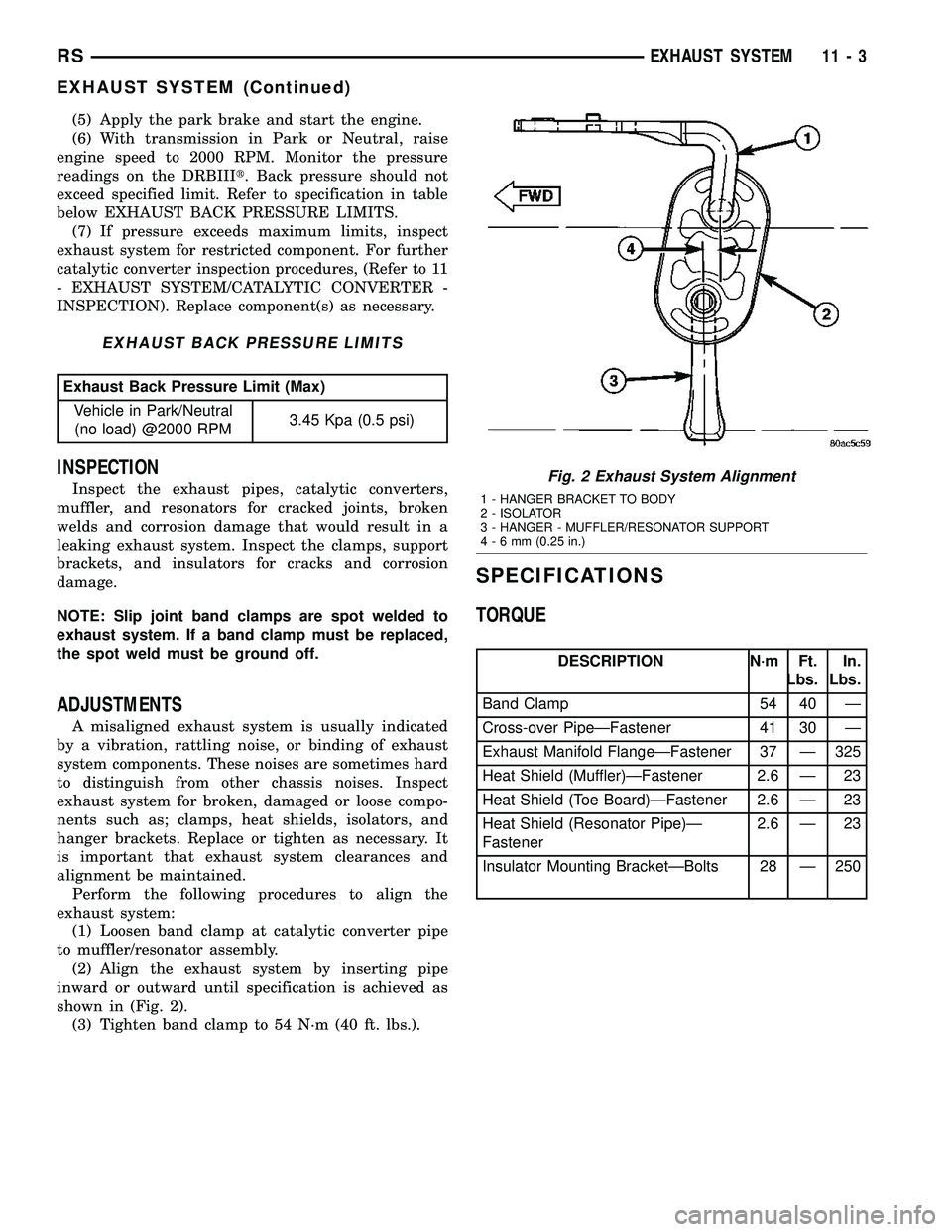
inward or outward until specification is achieved as
shown in (Fig. 2).
(3) Tighten band clamp to 54 N´m (40 ft. lbs.).
SPECIFICATIONS
TORQUE
DESCRIPTION N´m Ft.
Lbs.In.
Lbs.
Band Clamp 54 40 Ð
Cross-over PipeÐFastener 41 30 Ð
Exhaust Manifold FlangeÐFastener 37 Ð 325
Heat Shield (Muffler)ÐFastener 2.6 Ð 23
Heat Shield (Toe Board)ÐFastener 2.6 Ð 23
Heat Shield (Resonator Pipe)Ð
Fastener2.6 Ð 23
Insulator Mounting BracketÐBolts 28 Ð 250
Fig. 2 Exhaust System Alignment
1 - HANGER BRACKET TO BODY
2 - ISOLATOR
3 - HANGER - MUFFLER/RESONATOR SUPPORT
4-6mm(0.25 in.)
RSEXHAUST SYSTEM11-3
EXHAUST SYSTEM (Continued)
Page 1346 of 2339
NOTE: Maintain proper clamp orientation when
replacing with new clamp.
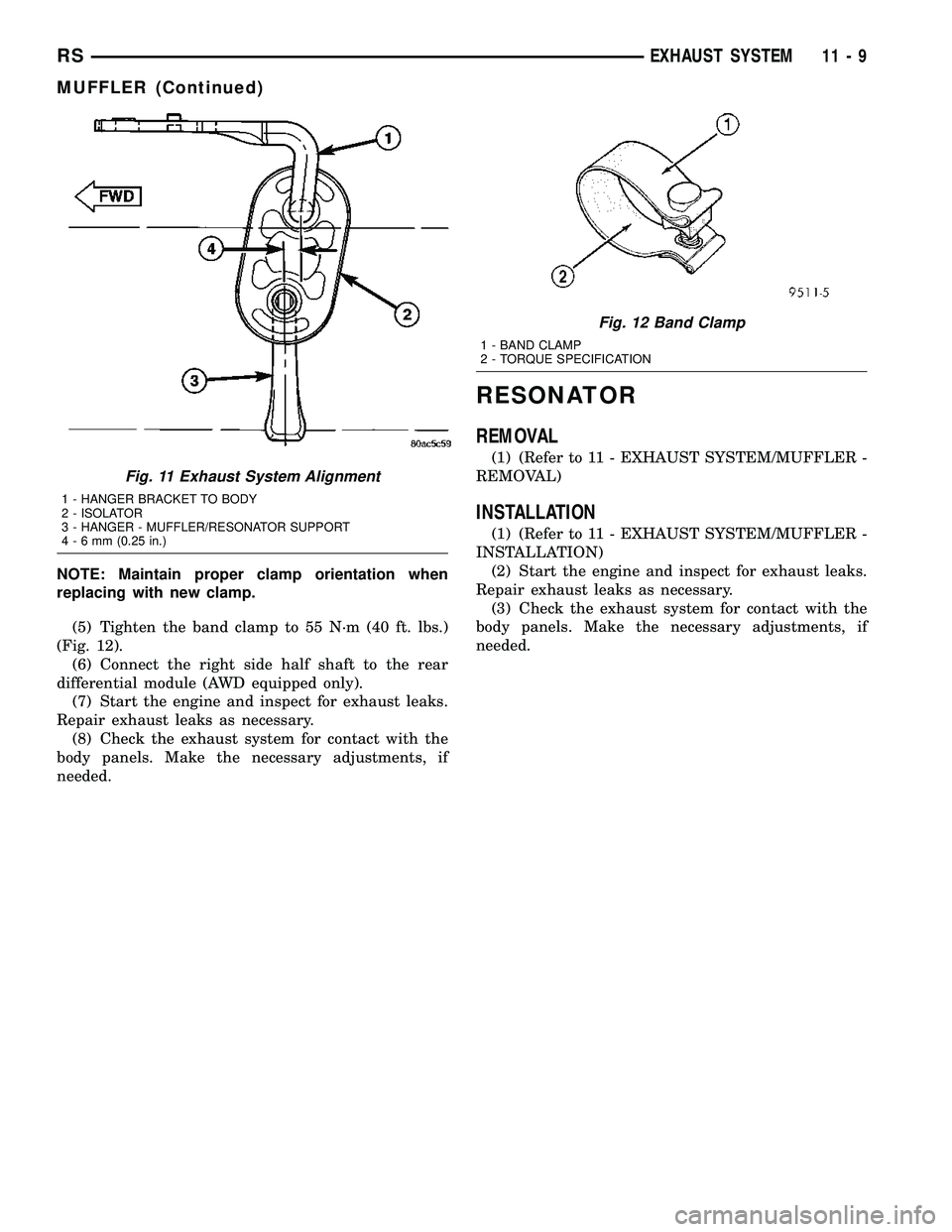
(5) Tighten the band clamp to 55 N´m (40 ft. lbs.)
(Fig. 12).
(6) Connect the right side half shaft to the rear
differential module (AWD equipped only).
(7) Start the engine and inspect for exhaust leaks.
Repair exhaust leaks as necessary.
(8) Check the exhaust system for contact with the
body panels. Make the necessary adjustments, if
needed.
RESONATOR
REMOVAL
(1) (Refer to 11 - EXHAUST SYSTEM/MUFFLER -
REMOVAL)
INSTALLATION
(1) (Refer to 11 - EXHAUST SYSTEM/MUFFLER -
INSTALLATION)
(2) Start the engine and inspect for exhaust leaks.
Repair exhaust leaks as necessary.
(3) Check the exhaust system for contact with the
body panels. Make the necessary adjustments, if
needed.
Fig. 11 Exhaust System Alignment
1 - HANGER BRACKET TO BODY
2 - ISOLATOR
3 - HANGER - MUFFLER/RESONATOR SUPPORT
4-6mm(0.25 in.)
Fig. 12 Band Clamp
1 - BAND CLAMP
2 - TORQUE SPECIFICATION
RSEXHAUST SYSTEM11-9
MUFFLER (Continued)
Page 1348 of 2339
FRAME & BUMPERS
TABLE OF CONTENTS
page page
BUMPERS
SPECIFICATIONS - TORQUE...............1
FRONT FASCIA
REMOVAL.............................1
INSTALLATION..........................1
FRONT BUMPER REINFORCEMENT
REMOVAL.............................3
INSTALLATION..........................3
REAR FASCIA
REMOVAL.............................4
INSTALLATION..........................4
REAR BUMPER REINFORCEMENT
REMOVAL.............................5
INSTALLATION..........................5
REAR FASCIA - SCUFF PAD
REMOVAL.............................5
INSTALLATION..........................5FRAME
SPECIFICATIONS
SPECIFICATIONS - FRAME DIMENSIONS . . . 6
SPECIFICATIONS - FRAME DIMENSIONS -
FOLD-IN-FLOOR SEATS ONLY...........11
SPECIFICATIONS - TORQUE............14
FRONT CRADLE CROSSMEMBER
DESCRIPTION
DESCRIPTION - FRONT CRADLE
CROSSMEMBER......................14
DESCRIPTION - FRONT CRADLE
CROSSMEMBER THREAD REPAIR........14
REMOVAL.............................15
INSTALLATION.........................16
FRONT CROSSMEMBER MOUNT BUSHINGS
REMOVAL.............................17
INSTALLATION.........................17
BUMPERS
SPECIFICATIONS - TORQUE
DESCRIPTION N´m Ft. Lbs. In. Lbs.
Front bumper reinforcement attaching nut 54 40 Ð
Rear bumper reinforcement attaching nut 27 20 Ð
FRONT FASCIA
REMOVAL
(1) Release hood latch and open hood.
(2) Remove the headlamp assemblies (Refer to 8 -
ELECTRICAL/LAMPS/LIGHTING - EXTERIOR/
HEADLAMP - REMOVAL).
(3) Hoist vehicle and support with safety stands.
(4) Remove the five push pin fasteners attaching
bottom of fascia/air dam to radiator closure panel.
(5) Remove front wheels.
(6) Remove front wheelhouse splash shields fasten-
ers as necessary to gain access to bolts attaching
front fascia to fender. (Refer to 23 - BODY/EXTERI-
OR/ WHEELHOUSE SPLASH SHIELD -
REMOVAL).(7) Remove the two bolts and two nuts attaching
fascia to the front fenders (Fig. 1) and (Fig. 2).
(8) Disconnect fog lamp wire connectors, if neces-
sary.
(9) Lower vehicle.
(10) Remove two bolts attaching the upper grille
support to the headlamp mounting panel at each side
of the grille.
(11) Remove bumper fascia from vehicle.
INSTALLATION
(1) Position front bumper fascia on vehicle (Fig. 1)
and (Fig. 2).
(2) Install the two bolts attaching fascia to head-
lamp mounting panel at each side of grille.
(3) Hoist vehicle and support with safety stands.
RSFRAME & BUMPERS13-1
Page 1351 of 2339
(1) Support front bumper reinforcement using a
suitable lifting device and lift into position.
(2) Install the four nuts attaching reinforcement to
frame rails. Tighten nuts to 54 N´m (40 ft. lbs.)
torque.
(3) Connect the solid state relay (SSR) wiring con-
nector. If bumper reinforcement was replaced, install
the solid state relay onto the bumper reinforcement.
(4) Install front fascia. (Refer to 13 - FRAMES &
BUMPERS/BUMPERS/FRONT FASCIA - INSTAL-
LATION).
REAR FASCIA
REMOVAL
(1) Open liftgate.
(2) Remove attaching screw from upper fascia to
the liftgate tower, right side and left side.
(3) Hoist and support vehicle with safety stands.
(4) Disconnect rear park assist wire connector, if
equipped.
(5) Remove the three screws attaching rear fascia
to rear fascia brackets on right side and left side
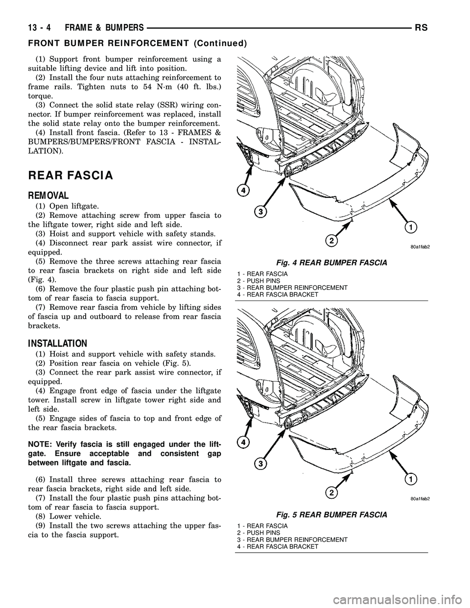
(Fig. 4).
(6) Remove the four plastic push pin attaching bot-
tom of rear fascia to fascia support.
(7) Remove rear fascia from vehicle by lifting sides
of fascia up and outboard to release from rear fascia
brackets.
INSTALLATION
(1) Hoist and support vehicle with safety stands.
(2) Position rear fascia on vehicle (Fig. 5).
(3) Connect the rear park assist wire connector, if
equipped.
(4) Engage front edge of fascia under the liftgate
tower. Install screw in liftgate tower right side and
left side.
(5) Engage sides of fascia to top and front edge of
the rear fascia brackets.
NOTE: Verify fascia is still engaged under the lift-
gate. Ensure acceptable and consistent gap
between liftgate and fascia.
(6) Install three screws attaching rear fascia to
rear fascia brackets, right side and left side.
(7) Install the four plastic push pins attaching bot-
tom of rear fascia to fascia support.
(8) Lower vehicle.
(9) Install the two screws attaching the upper fas-
cia to the fascia support.
Fig. 4 REAR BUMPER FASCIA
1 - REAR FASCIA
2 - PUSH PINS
3 - REAR BUMPER REINFORCEMENT
4 - REAR FASCIA BRACKET
Fig. 5 REAR BUMPER FASCIA
1 - REAR FASCIA
2 - PUSH PINS
3 - REAR BUMPER REINFORCEMENT
4 - REAR FASCIA BRACKET
13 - 4 FRAME & BUMPERSRS
FRONT BUMPER REINFORCEMENT (Continued)