2005 CHRYSLER CARAVAN torque
[x] Cancel search: torquePage 1209 of 2339
INSTALLATION
NOTE: Replace spark plug well seals and bolt
assemblies when installing a new cylinder head
cover gasket.
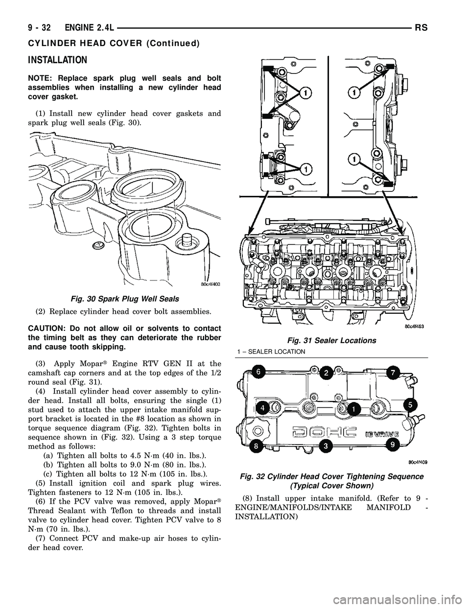
(1) Install new cylinder head cover gaskets and
spark plug well seals (Fig. 30).
(2) Replace cylinder head cover bolt assemblies.
CAUTION: Do not allow oil or solvents to contact
the timing belt as they can deteriorate the rubber
and cause tooth skipping.
(3) Apply MopartEngine RTV GEN II at the
camshaft cap corners and at the top edges of the 1/2
round seal (Fig. 31).
(4) Install cylinder head cover assembly to cylin-
der head. Install all bolts, ensuring the single (1)
stud used to attach the upper intake manifold sup-
port bracket is located in the #8 location as shown in
torque sequence diagram (Fig. 32). Tighten bolts in
sequence shown in (Fig. 32). Using a 3 step torque
method as follows:
(a) Tighten all bolts to 4.5 N´m (40 in. lbs.).
(b) Tighten all bolts to 9.0 N´m (80 in. lbs.).
(c) Tighten all bolts to 12 N´m (105 in. lbs.).
(5) Install ignition coil and spark plug wires.
Tighten fasteners to 12 N´m (105 in. lbs.).
(6) If the PCV valve was removed, apply Mopart
Thread Sealant with Teflon to threads and install
valve to cylinder head cover. Tighten PCV valve to 8
N´m (70 in. lbs.).
(7) Connect PCV and make-up air hoses to cylin-
der head cover.(8) Install upper intake manifold. (Refer to 9 -
ENGINE/MANIFOLDS/INTAKE MANIFOLD -
INSTALLATION)
Fig. 30 Spark Plug Well Seals
Fig. 31 Sealer Locations
1 ± SEALER LOCATION
Fig. 32 Cylinder Head Cover Tightening Sequence
(Typical Cover Shown)
9 - 32 ENGINE 2.4LRS
CYLINDER HEAD COVER (Continued)
Page 1216 of 2339
thrust faces of No. 3 main bearing. DO NOT nick
crank pin or bearing fillets. After grinding, remove
rough edges from crankshaft oil holes and clean out
all passages.
CAUTION: With the nodular cast iron crankshafts, it
is important that the final paper or cloth polish be
in the same direction as normal rotation in the
engine.
INSTALLATION - CRANKSHAFT
CRANKSHAFT MAIN BEARING LOCATION
The crankshaft is supported in five main bearings.
All upper bearing shells in the crankcase have oil
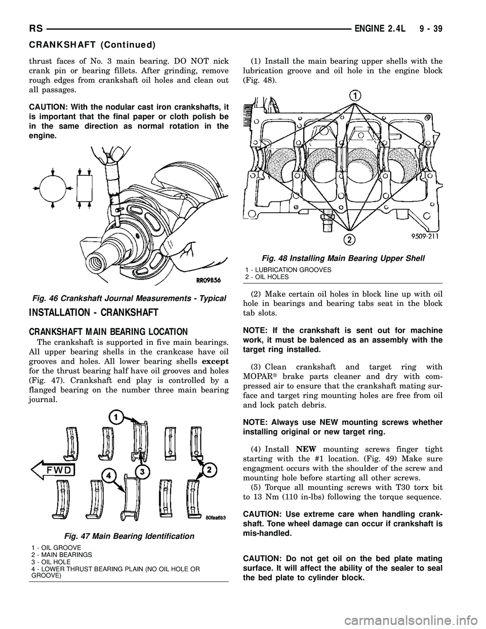
grooves and holes. All lower bearing shellsexcept
for the thrust bearing half have oil grooves and holes
(Fig. 47). Crankshaft end play is controlled by a
flanged bearing on the number three main bearing
journal.(1) Install the main bearing upper shells with the
lubrication groove and oil hole in the engine block
(Fig. 48).
(2) Make certain oil holes in block line up with oil
hole in bearings and bearing tabs seat in the block
tab slots.
NOTE: If the crankshaft is sent out for machine
work, it must be balenced as an assembly with the
target ring installed.
(3) Clean crankshaft and target ring with
MOPARtbrake parts cleaner and dry with com-
pressed air to ensure that the crankshaft mating sur-
face and target ring mounting holes are free from oil
and lock patch debris.
NOTE: Always use NEW mounting screws whether
installing original or new target ring.
(4) InstallNEWmounting screws finger tight
starting with the #1 location. (Fig. 49) Make sure
engagment occurs with the shoulder of the screw and
mounting hole before starting all other screws.
(5) Torque all mounting screws with T30 torx bit
to 13 Nm (110 in-lbs) following the torque sequence.
CAUTION: Use extreme care when handling crank-
shaft. Tone wheel damage can occur if crankshaft is
mis-handled.
CAUTION: Do not get oil on the bed plate mating
surface. It will affect the ability of the sealer to seal
the bed plate to cylinder block.
Fig. 46 Crankshaft Journal Measurements - Typical
Fig. 47 Main Bearing Identification
1 - OIL GROOVE
2 - MAIN BEARINGS
3 - OIL HOLE
4 - LOWER THRUST BEARING PLAIN (NO OIL HOLE OR
GROOVE)
Fig. 48 Installing Main Bearing Upper Shell
1 - LUBRICATION GROOVES
2 - OIL HOLES
RSENGINE 2.4L9-39
CRANKSHAFT (Continued)
Page 1217 of 2339
(6) Oil the bearings and journals. Install crank-
shaft in the engine block.
CAUTION: Use only MoparTBed Plate Sealant on
the bed plate or damage may occur to the engine.
(7) Install lower main bearings into main bearing
cap/bed plate. Make certain the bearing tabs are
seated into the bed plate slots and apply oil.
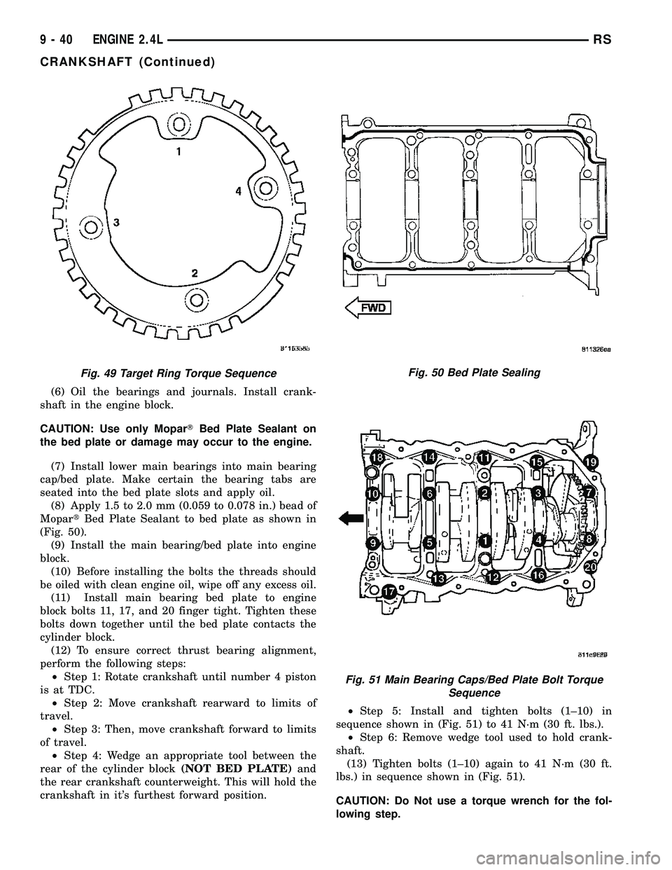
(8) Apply 1.5 to 2.0 mm (0.059 to 0.078 in.) bead of
MopartBed Plate Sealant to bed plate as shown in
(Fig. 50).
(9) Install the main bearing/bed plate into engine
block.
(10) Before installing the bolts the threads should
be oiled with clean engine oil, wipe off any excess oil.
(11) Install main bearing bed plate to engine
block bolts 11, 17, and 20 finger tight. Tighten these
bolts down together until the bed plate contacts the
cylinder block.
(12) To ensure correct thrust bearing alignment,
perform the following steps:
²Step 1: Rotate crankshaft until number 4 piston
is at TDC.
²Step 2: Move crankshaft rearward to limits of
travel.
²Step 3: Then, move crankshaft forward to limits
of travel.
²Step 4: Wedge an appropriate tool between the
rear of the cylinder block(NOT BED PLATE)and
the rear crankshaft counterweight. This will hold the
crankshaft in it's furthest forward position.²Step 5: Install and tighten bolts (1±10) in
sequence shown in (Fig. 51) to 41 N´m (30 ft. lbs.).
²Step 6: Remove wedge tool used to hold crank-
shaft.
(13) Tighten bolts (1±10) again to 41 N´m (30 ft.
lbs.) in sequence shown in (Fig. 51).
CAUTION: Do Not use a torque wrench for the fol-
lowing step.
Fig. 49 Target Ring Torque SequenceFig. 50 Bed Plate Sealing
Fig. 51 Main Bearing Caps/Bed Plate Bolt Torque
Sequence
9 - 40 ENGINE 2.4LRS
CRANKSHAFT (Continued)
Page 1218 of 2339
(14) Turn bolts (1±10) an additional 1/4 turn in
sequence shown in (Fig. 51).
(15) Install main bearing bed plate to engine
block bolts (11±20), and torque each bolt to 28 N´m
(250 in. lbs.) in sequence shown in. (Fig. 51)
(16) Tighten bolts (11±20) again to 28 N´m (250 in.
lbs.) in sequence shown in (Fig. 51).
(17) After the main bearing bed plate is installed,
check the crankshaft turning torque. The turning
torque should not exceed 5.6 N´m (50 in. lbs.).
(18) Check crankshaft end play (Refer to 9 -
ENGINE/ENGINE BLOCK/CRANKSHAFT - STAN-
DARD PROCEDURE).
(19) Install connecting rod bearings and caps.Do
Not Reuse Connecting Rod Bolts.Torque connect-
ing rod bolts to 27 N´m (20 ft. lbs.) plus 1/4 turn.
(20) Install balance shafts and housing assembly
(Refer to 9 - ENGINE/VALVE TIMING/BALANCE
SHAFT - INSTALLATION).
(21) Install the oil pump (Refer to 9 - ENGINE/
LUBRICATION/OIL PUMP - INSTALLATION).
(22) Install oil pump pick-up tube. Torque fastener
to 28 N´m (20 ft.. lbs.).
(23) Install the oil pan (Refer to 9 - ENGINE/LU-
BRICATION/OIL PAN - INSTALLATION).
(24) Install crankshaft position sensor.
(25) Install cylinder head if it was removed (Refer
to 9 - ENGINE/CYLINDER HEAD - INSTALLA-
TION).
(26) Install the timing belt rear cover (Refer to 9 -
ENGINE/VALVE TIMING/TIMING BELT COVER(S)
- INSTALLATION).
(27) Install crankshaft sprocket (Refer to 9 -
ENGINE/VALVE TIMING/TIMING BELT AND
SPROCKETS - INSTALLATION).
(28) Install the timing belt (Refer to 9 - ENGINE/
VALVE TIMING/TIMING BELT AND SPROCKETS -
INSTALLATION).
(29) Install the timing belt front covers (Refer to 9
- ENGINE/VALVE TIMING/TIMING BELT COV-
ER(S) - INSTALLATION).
(30) Install engine mount support bracket.
(31) InstallNEWoil filter.
(32) Install crankshaft rear oil seal (Refer to 9 -
ENGINE/ENGINE BLOCK/CRANKSHAFT OIL
SEAL - REAR - INSTALLATION).
(33) Install flex plate. Apply MopartLock & Seal
Adhesive to bolt threads and tighten to 95 N´m (70
ft. lbs.).
(34) Attach transaxle to engine. Tighten attaching
bolts to 101 N´m (75 ft. lbs.).
(35) Install the engine assembly (Refer to 9 -
ENGINE - INSTALLATION).CRANKSHAFT OIL SEAL -
FRONT
REMOVAL
(1) Remove the crankshaft vibration damper.
(Refer to 9 - ENGINE/ENGINE BLOCK/VIBRATION
DAMPER - REMOVAL)
(2) Remove timing belt. (Refer to 9 - ENGINE/
VALVE TIMING/TIMING BELT/CHAIN AND
SPROCKETS - REMOVAL)
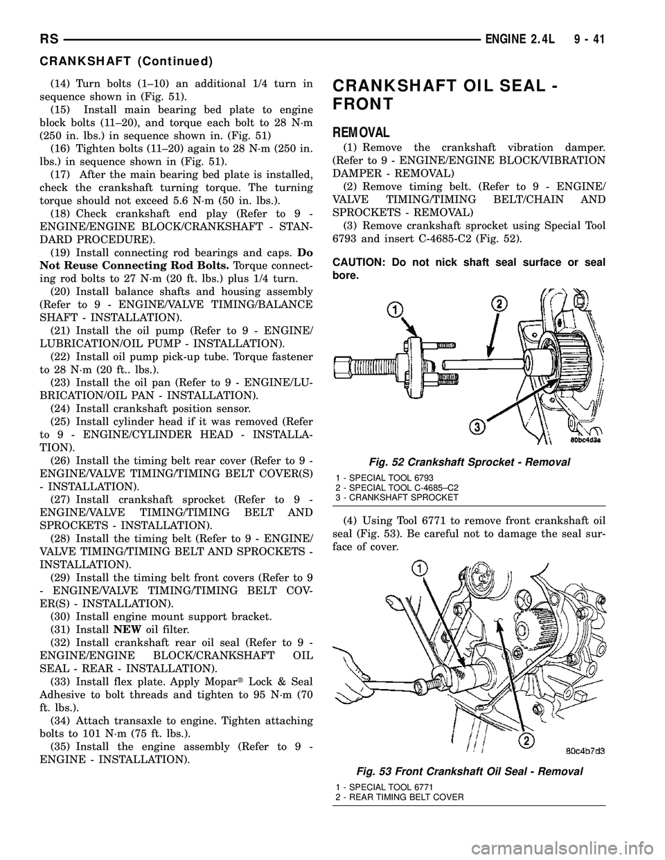
(3) Remove crankshaft sprocket using Special Tool
6793 and insert C-4685-C2 (Fig. 52).
CAUTION: Do not nick shaft seal surface or seal
bore.
(4) Using Tool 6771 to remove front crankshaft oil
seal (Fig. 53). Be careful not to damage the seal sur-
face of cover.
Fig. 52 Crankshaft Sprocket - Removal
1 - SPECIAL TOOL 6793
2 - SPECIAL TOOL C-4685±C2
3 - CRANKSHAFT SPROCKET
Fig. 53 Front Crankshaft Oil Seal - Removal
1 - SPECIAL TOOL 6771
2 - REAR TIMING BELT COVER
RSENGINE 2.4L9-41
CRANKSHAFT (Continued)
Page 1223 of 2339
(6) Rotate crankshaft so that the connecting rod
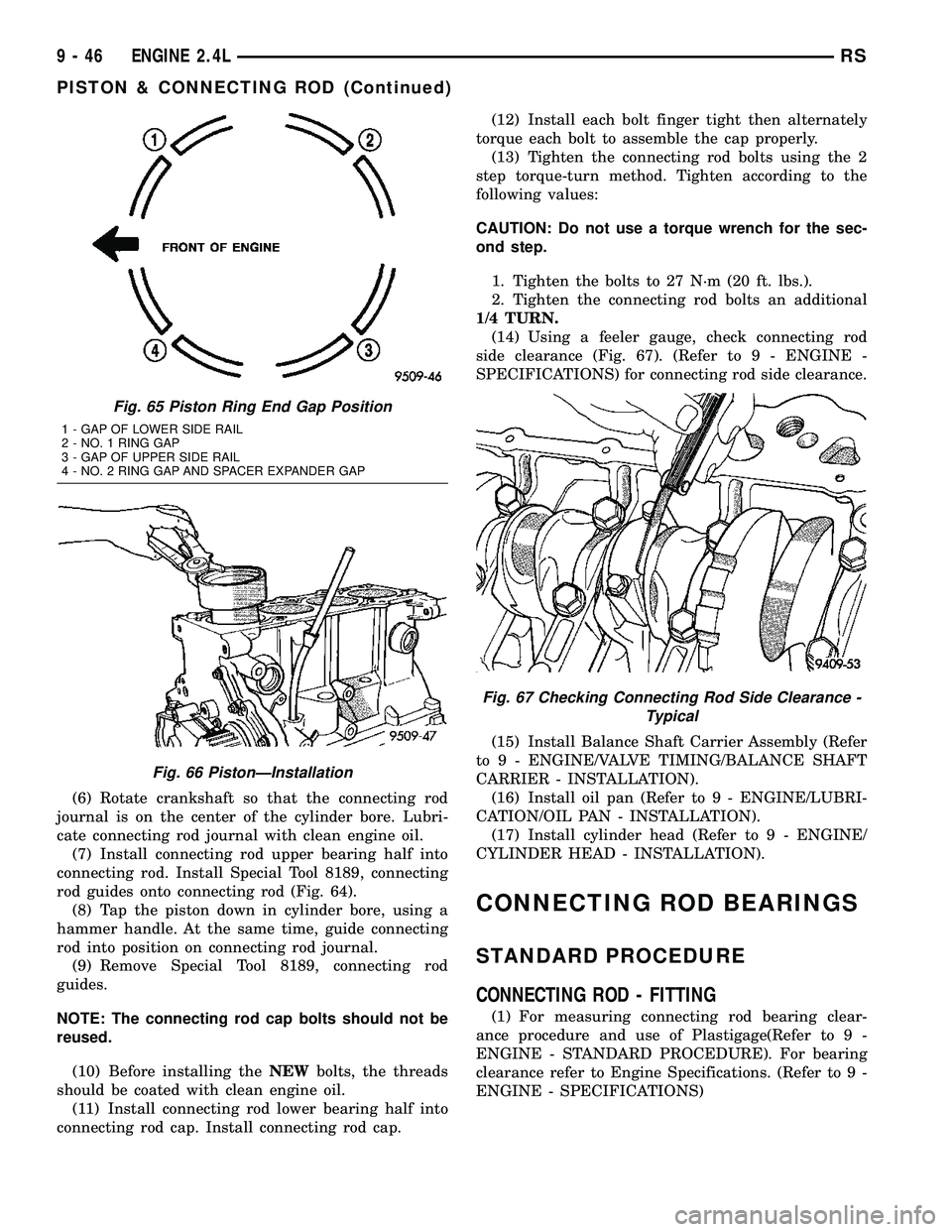
journal is on the center of the cylinder bore. Lubri-
cate connecting rod journal with clean engine oil.
(7) Install connecting rod upper bearing half into
connecting rod. Install Special Tool 8189, connecting
rod guides onto connecting rod (Fig. 64).
(8) Tap the piston down in cylinder bore, using a
hammer handle. At the same time, guide connecting
rod into position on connecting rod journal.
(9) Remove Special Tool 8189, connecting rod
guides.
NOTE: The connecting rod cap bolts should not be
reused.
(10) Before installing theNEWbolts, the threads
should be coated with clean engine oil.
(11) Install connecting rod lower bearing half into
connecting rod cap. Install connecting rod cap.(12) Install each bolt finger tight then alternately
torque each bolt to assemble the cap properly.
(13) Tighten the connecting rod bolts using the 2
step torque-turn method. Tighten according to the
following values:
CAUTION: Do not use a torque wrench for the sec-
ond step.
1. Tighten the bolts to 27 N´m (20 ft. lbs.).
2. Tighten the connecting rod bolts an additional
1/4 TURN.
(14) Using a feeler gauge, check connecting rod
side clearance (Fig. 67). (Refer to 9 - ENGINE -
SPECIFICATIONS) for connecting rod side clearance.
(15) Install Balance Shaft Carrier Assembly (Refer
to 9 - ENGINE/VALVE TIMING/BALANCE SHAFT
CARRIER - INSTALLATION).
(16) Install oil pan (Refer to 9 - ENGINE/LUBRI-
CATION/OIL PAN - INSTALLATION).
(17) Install cylinder head (Refer to 9 - ENGINE/
CYLINDER HEAD - INSTALLATION).
CONNECTING ROD BEARINGS
STANDARD PROCEDURE
CONNECTING ROD - FITTING
(1) For measuring connecting rod bearing clear-
ance procedure and use of Plastigage(Refer to 9 -
ENGINE - STANDARD PROCEDURE). For bearing
clearance refer to Engine Specifications. (Refer to 9 -
ENGINE - SPECIFICATIONS)
Fig. 65 Piston Ring End Gap Position
1 - GAP OF LOWER SIDE RAIL
2 - NO. 1 RING GAP
3 - GAP OF UPPER SIDE RAIL
4 - NO. 2 RING GAP AND SPACER EXPANDER GAP
Fig. 66 PistonÐInstallation
Fig. 67 Checking Connecting Rod Side Clearance -
Typical
9 - 46 ENGINE 2.4LRS
PISTON & CONNECTING ROD (Continued)
Page 1224 of 2339
NOTE: The rod bearing bolts should not be reused.
(2) Before installing theNEWbolts the threads
should be oiled with clean engine oil.
(3) Install each bolt finger tight then alternately
torque each bolt to assemble the cap properly.
(4) Tighten the connecting rod bolts using the 2
step torque-turn method. Tighten according to the
following values:
CAUTION: Do not use a torque wrench for the sec-
ond step.
1. Tighten the bolts to 27 N´m (20 ft. lbs.).
2. Tighten the connecting rod bolts an additional
1/4 TURN.
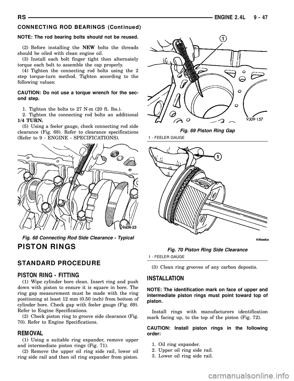
(5) Using a feeler gauge, check connecting rod side
clearance (Fig. 68). Refer to clearance specifications
(Refer to 9 - ENGINE - SPECIFICATIONS).
PISTON RINGS
STANDARD PROCEDURE
PISTON RING - FITTING
(1) Wipe cylinder bore clean. Insert ring and push
down with piston to ensure it is square in bore. The
ring gap measurement must be made with the ring
positioning at least 12 mm (0.50 inch) from bottom of
cylinder bore. Check gap with feeler gauge (Fig. 69).
Refer to Engine Specifications.
(2) Check piston ring to groove side clearance (Fig.
70). Refer to Engine Specifications.
REMOVAL
(1) Using a suitable ring expander, remove upper
and intermediate piston rings (Fig. 71).
(2) Remove the upper oil ring side rail, lower oil
ring side rail and then oil ring expander from piston.(3) Clean ring grooves of any carbon deposits.
INSTALLATION
NOTE: The identification mark on face of upper and
intermediate piston rings must point toward top of
piston.
Install rings with manufacturers identification
mark facing up, to the top of the piston (Fig. 72).
CAUTION: Install piston rings in the following
order:
1. Oil ring expander.
2. Upper oil ring side rail.
3. Lower oil ring side rail.
Fig. 68 Connecting Rod Side Clearance - Typical
Fig. 69 Piston Ring Gap
1 - FEELER GAUGE
Fig. 70 Piston Ring Side Clearance
1 - FEELER GAUGE
RSENGINE 2.4L9-47
CONNECTING ROD BEARINGS (Continued)
Page 1226 of 2339
INSTALLATION
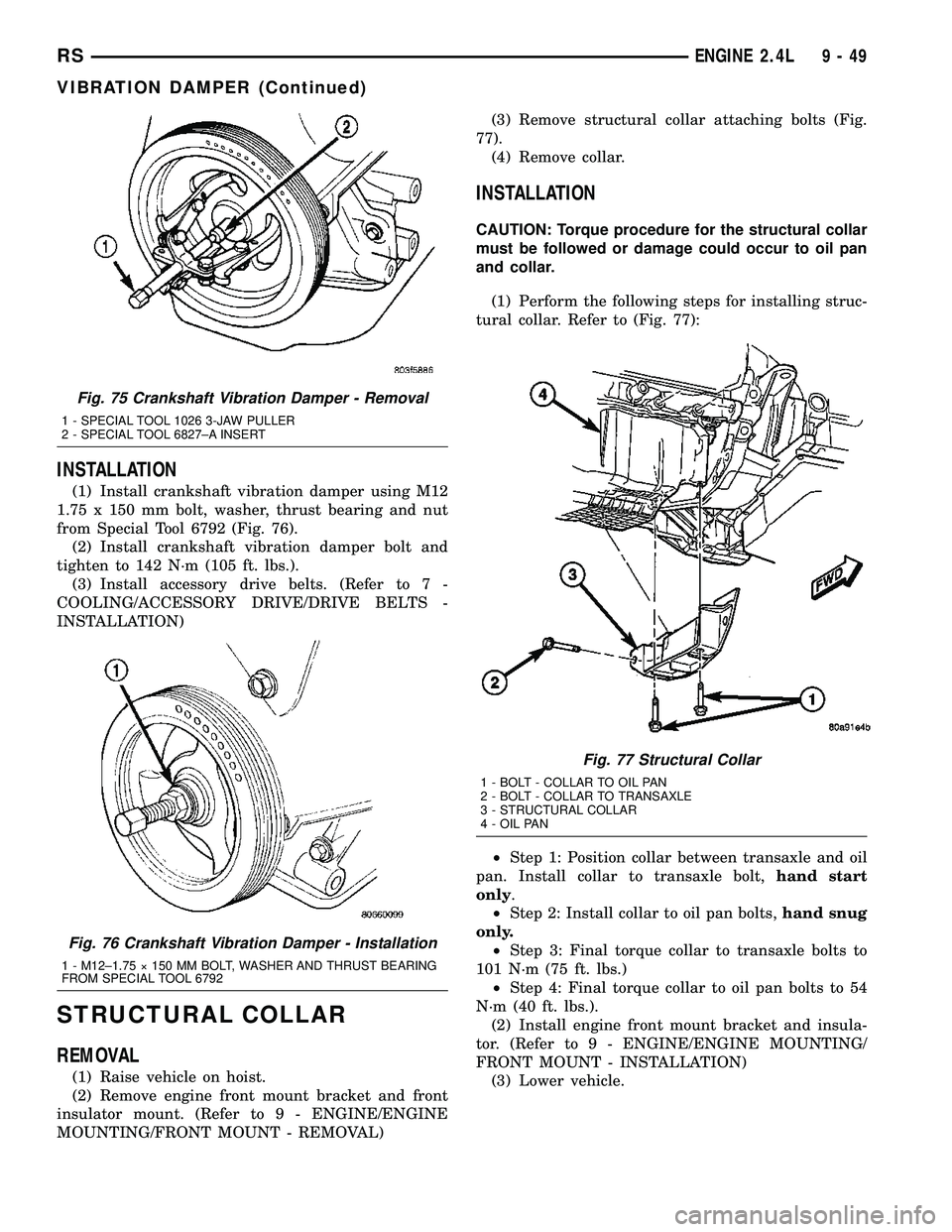
(1) Install crankshaft vibration damper using M12
1.75 x 150 mm bolt, washer, thrust bearing and nut
from Special Tool 6792 (Fig. 76).
(2) Install crankshaft vibration damper bolt and
tighten to 142 N´m (105 ft. lbs.).
(3) Install accessory drive belts. (Refer to 7 -
COOLING/ACCESSORY DRIVE/DRIVE BELTS -
INSTALLATION)
STRUCTURAL COLLAR
REMOVAL
(1) Raise vehicle on hoist.
(2) Remove engine front mount bracket and front
insulator mount. (Refer to 9 - ENGINE/ENGINE
MOUNTING/FRONT MOUNT - REMOVAL)(3) Remove structural collar attaching bolts (Fig.
77).
(4) Remove collar.
INSTALLATION
CAUTION: Torque procedure for the structural collar
must be followed or damage could occur to oil pan
and collar.
(1) Perform the following steps for installing struc-
tural collar. Refer to (Fig. 77):
²Step 1: Position collar between transaxle and oil
pan. Install collar to transaxle bolt,hand start
only.
²Step 2: Install collar to oil pan bolts,hand snug
only.
²Step 3: Final torque collar to transaxle bolts to
101 N´m (75 ft. lbs.)
²Step 4: Final torque collar to oil pan bolts to 54
N´m (40 ft. lbs.).
(2) Install engine front mount bracket and insula-
tor. (Refer to 9 - ENGINE/ENGINE MOUNTING/
FRONT MOUNT - INSTALLATION)
(3) Lower vehicle.
Fig. 75 Crankshaft Vibration Damper - Removal
1 - SPECIAL TOOL 1026 3-JAW PULLER
2 - SPECIAL TOOL 6827±A INSERT
Fig. 76 Crankshaft Vibration Damper - Installation
1 - M12±1.75 ý 150 MM BOLT, WASHER AND THRUST BEARING
FROM SPECIAL TOOL 6792
Fig. 77 Structural Collar
1 - BOLT - COLLAR TO OIL PAN
2 - BOLT - COLLAR TO TRANSAXLE
3 - STRUCTURAL COLLAR
4 - OIL PAN
RSENGINE 2.4L9-49
VIBRATION DAMPER (Continued)
Page 1227 of 2339
ENGINE MOUNTING
DESCRIPTION
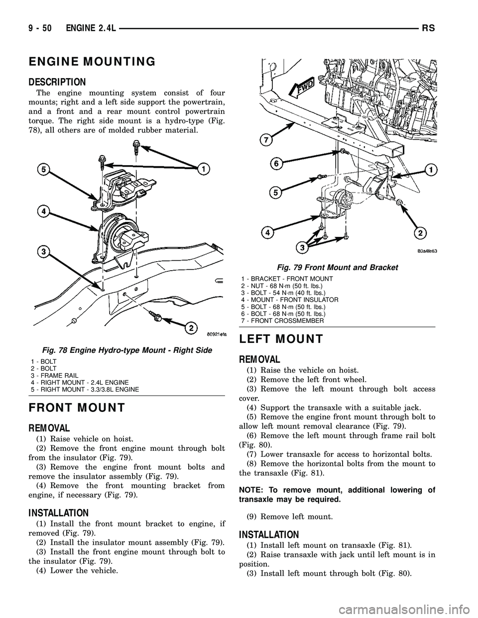
The engine mounting system consist of four
mounts; right and a left side support the powertrain,
and a front and a rear mount control powertrain
torque. The right side mount is a hydro-type (Fig.
78), all others are of molded rubber material.
FRONT MOUNT
REMOVAL
(1) Raise vehicle on hoist.
(2) Remove the front engine mount through bolt
from the insulator (Fig. 79).
(3) Remove the engine front mount bolts and
remove the insulator assembly (Fig. 79).
(4) Remove the front mounting bracket from
engine, if necessary (Fig. 79).
INSTALLATION
(1) Install the front mount bracket to engine, if
removed (Fig. 79).
(2) Install the insulator mount assembly (Fig. 79).
(3) Install the front engine mount through bolt to
the insulator (Fig. 79).
(4) Lower the vehicle.
LEFT MOUNT
REMOVAL
(1) Raise the vehicle on hoist.
(2) Remove the left front wheel.
(3) Remove the left mount through bolt access
cover.
(4) Support the transaxle with a suitable jack.
(5) Remove the engine front mount through bolt to
allow left mount removal clearance (Fig. 79).
(6) Remove the left mount through frame rail bolt
(Fig. 80).
(7) Lower transaxle for access to horizontal bolts.
(8) Remove the horizontal bolts from the mount to
the transaxle (Fig. 81).
NOTE: To remove mount, additional lowering of
transaxle may be required.
(9) Remove left mount.
INSTALLATION
(1) Install left mount on transaxle (Fig. 81).
(2) Raise transaxle with jack until left mount is in
position.
(3) Install left mount through bolt (Fig. 80).
Fig. 78 Engine Hydro-type Mount - Right Side
1 - BOLT
2 - BOLT
3 - FRAME RAIL
4 - RIGHT MOUNT - 2.4L ENGINE
5 - RIGHT MOUNT - 3.3/3.8L ENGINE
Fig. 79 Front Mount and Bracket
1 - BRACKET - FRONT MOUNT
2 - NUT - 68 N´m (50 ft. lbs.)
3 - BOLT - 54 N´m (40 ft. lbs.)
4 - MOUNT - FRONT INSULATOR
5 - BOLT - 68 N´m (50 ft. lbs.)
6 - BOLT - 68 N´m (50 ft. lbs.)
7 - FRONT CROSSMEMBER
9 - 50 ENGINE 2.4LRS