2005 CHRYSLER CARAVAN light
[x] Cancel search: lightPage 1819 of 2339
DECKLID/HATCH/LIFTGATE/TAILGATE
TABLE OF CONTENTS
page page
EXTERIOR HANDLE
REMOVAL.............................40
INSTALLATION.........................40
HINGE
REMOVAL.............................40
INSTALLATION.........................40
LATCH
REMOVAL.............................41
INSTALLATION.........................41
LATCH STRIKER
REMOVAL.............................41
INSTALLATION.........................42
LIFTGATE
REMOVAL.............................42
INSTALLATION.........................42
LOCK CYLINDER
REMOVAL.............................42INSTALLATION.........................42
SUPPORT CYLINDER
REMOVAL.............................42
INSTALLATION.........................43
TRIM PANEL
REMOVAL.............................43
INSTALLATION.........................43
SLAM BUMPER
REMOVAL
REMOVAL - BODY SIDE................44
REMOVAL - LIFTGATE SIDE.............44
INSTALLATION
INSTALLATION - BODY SIDE............44
INSTALLATION - LIFTGATE SIDE.........44
EXTERIOR HANDLE
REMOVAL
(1) Remove liftgate trim panel. (Refer to 23 -
BODY/DECKLID/HATCH/LIFTGATE/TAILGATE/
TRIM PANEL - REMOVAL)
(2) Disconnect the exterior handle electrical con-
nectors.
(3) Remove the two outer screws and the two inner
screws.
(4) Remove the exterior handle/license plate light
assembly.
INSTALLATION
(1) Route the exterior handle electrical connector
through the door and position handle.
(2) Install the two out screws and tighten to 3 N´m
(22 in. lbs.).
(3) Install the two inner bolts and tighten to 5
N´m (40 in. lbs.).
(4) Connect the electrical connector.
(5) Install the trim panel. (Refer to 23 - BODY/
DECKLID/HATCH/LIFTGATE/TAILGATE/TRIM
PANEL - INSTALLATION)
HINGE
REMOVAL
(1) Release liftgate latch and open liftgate.
(2) Support liftgate on a suitable lifting device in
the full open position.
(3) Apply several layers of duct tape on the outside
of to roof across the gap to the lift gate to hold the
liftgate in position.
(4) Remove bolts attaching liftgate hinge to roof
header.
(5) Disconnect VTSS switch from the body har-
ness.
(6) Remove bolts attaching hinge to liftgate (Fig.
1).
(7) Remove hinge from vehicle.
INSTALLATION
(1) If necessary, paint replacement hinge before
installation.
(2) Place hinge in position on vehicle.
(3) Align hinge to marks on liftgate.
(4) Install bolts attaching hinge to liftgate (Fig. 1).
Tighten bolts to 33 N´m (24 ft. lbs.) torque.
(5) Align hinge to marks on roof header.
23 - 40 DECKLID/HATCH/LIFTGATE/TAILGATERS
Page 1830 of 2339
(7) Tighten screw to 1.2 N´m (11 in. lbs.) torque.
(8) Install the wiper arms. (Refer to 8 - ELECTRI-
CAL/WIPERS/WASHERS/WIPER ARMS - INSTAL-
LATION)
(9) Check for proper spray pattern from washer
nozzles.
EXTERIOR NAME PLATES -
TAPE ATTACHED
REMOVAL
(1) Mark reference points before removing.
(2) Using a heat gun gently apply heat in a circu-
lar motion to loosen the adhesive bond.
(3) Using a nonmetallic prying device, such as a
plastic or wood trim stick gently pry up at corners
and remove.
(4) Clean off all traces of adhesive or double sided
tape from the panel with a general purpose adhesive
remover.
INSTALLATION
(1) Clean panel surface with isopropy alcohol.
(2) Align badgeing to reference points.
(3) Install and press securely to full adhesive con-
tact
(4) Clean away any reference points.
EXTERIOR NAME PLATES -
ADHESIVE ATTACHED
REMOVAL
(1) Mark reference points before removing.
(2) Using a heat gun gently apply heat in a circu-
lar motion to loosen the adhesive bond.
(3) With your fingernail lift up and peel away
badgeing/tape from panel, using a heat gun as you
go.
(4) Clean off all traces of adhesive from the pan-
el(s) with a general purpose adhesive remover.
INSTALLATION
(1) Clean panel surface with isopropy alcohol.
(2) Remove paper carrier and align badgeing/tape
to reference points or adjacent panel.
(3) Install and press securely, using a plastic
spreader to eliminate all air bubbles.
(4) Remove top protective carrier.
(5) Clean away any reference points.
FRONT FENDER
REMOVAL
(1) Remove headlamp housing. (Refer to 8 - ELEC-
TRICAL/LAMPS/LIGHTING - EXTERIOR/HEAD-
LAMP UNIT - REMOVAL)
(2) Remove mirror bezel
(3) Remove mud guard.
(4) Remove inner splash shield.
(5) Remove fender to fascia nuts.
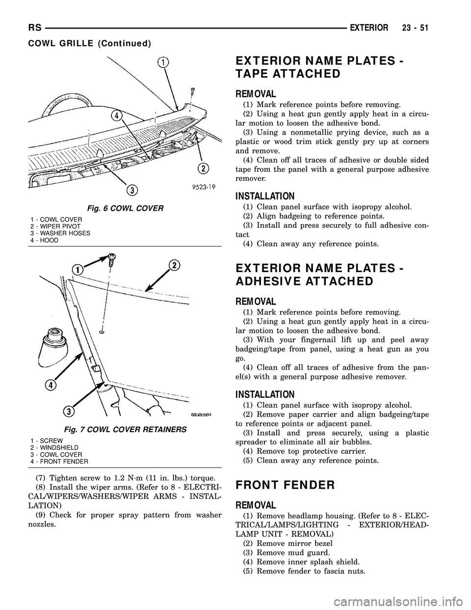
Fig. 6 COWL COVER
1 - COWL COVER
2 - WIPER PIVOT
3 - WASHER HOSES
4 - HOOD
Fig. 7 COWL COVER RETAINERS
1 - SCREW
2 - WINDSHIELD
3 - COWL COVER
4 - FRONT FENDER
RSEXTERIOR23-51
COWL GRILLE (Continued)
Page 1831 of 2339
(6) Remove outboard cowl grille/fender bracket
screw and antenna right side only.
(7) Remove fender bolt to lower rocker panel.
(8) Remove fender bolt to lower cowl.
(9) Support/remove hood.
(10) Pull fascia away from fender.
(11) Remove bolts attaching fender to upper rail.
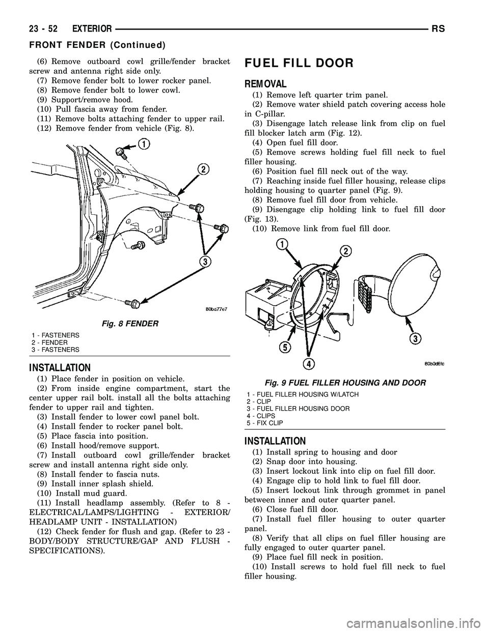
(12) Remove fender from vehicle (Fig. 8).
INSTALLATION
(1) Place fender in position on vehicle.
(2) From inside engine compartment, start the
center upper rail bolt. install all the bolts attaching
fender to upper rail and tighten.
(3) Install fender to lower cowl panel bolt.
(4) Install fender to rocker panel bolt.
(5) Place fascia into position.
(6) Install hood/remove support.
(7) Install outboard cowl grille/fender bracket
screw and install antenna right side only.
(8) Install fender to fascia nuts.
(9) Install inner splash shield.
(10) Install mud guard.
(11) Install headlamp assembly. (Refer to 8 -
ELECTRICAL/LAMPS/LIGHTING - EXTERIOR/
HEADLAMP UNIT - INSTALLATION)
(12) Check fender for flush and gap. (Refer to 23 -
BODY/BODY STRUCTURE/GAP AND FLUSH -
SPECIFICATIONS).
FUEL FILL DOOR
REMOVAL
(1) Remove left quarter trim panel.
(2) Remove water shield patch covering access hole
in C-pillar.
(3) Disengage latch release link from clip on fuel
fill blocker latch arm (Fig. 12).
(4) Open fuel fill door.
(5) Remove screws holding fuel fill neck to fuel
filler housing.
(6) Position fuel fill neck out of the way.
(7) Reaching inside fuel filler housing, release clips
holding housing to quarter panel (Fig. 9).
(8) Remove fuel fill door from vehicle.
(9) Disengage clip holding link to fuel fill door
(Fig. 13).
(10) Remove link from fuel fill door.
INSTALLATION
(1) Install spring to housing and door
(2) Snap door into housing.
(3) Insert lockout link into clip on fuel fill door.
(4) Engage clip to hold link to fuel fill door.
(5) Insert lockout link through grommet in panel
between inner and outer quarter panel.
(6) Close fuel fill door.
(7) Install fuel filler housing to outer quarter
panel.
(8) Verify that all clips on fuel filler housing are
fully engaged to outer quarter panel.
(9) Place fuel fill neck in position.
(10) Install screws to hold fuel fill neck to fuel
filler housing.
Fig. 8 FENDER
1 - FASTENERS
2 - FENDER
3 - FASTENERS
Fig. 9 FUEL FILLER HOUSING AND DOOR
1 - FUEL FILLER HOUSING W/LATCH
2 - CLIP
3 - FUEL FILLER HOUSING DOOR
4 - CLIPS
5 - FIX CLIP
23 - 52 EXTERIORRS
FRONT FENDER (Continued)
Page 1856 of 2339
INSTRUMENT PANEL TOP PAD
ASSEMBLY
REMOVAL
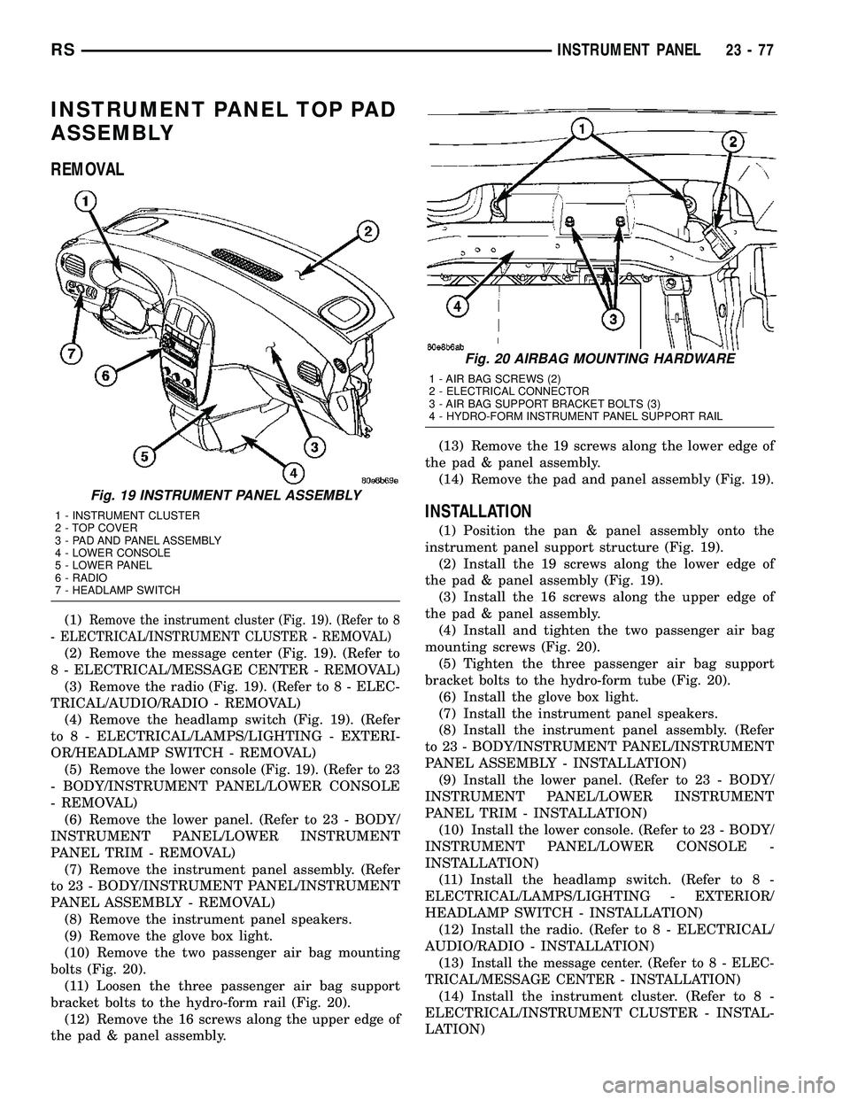
(1)Remove the instrument cluster (Fig. 19). (Refer to 8
- ELECTRICAL/INSTRUMENT CLUSTER - REMOVAL)
(2) Remove the message center (Fig. 19). (Refer to
8 - ELECTRICAL/MESSAGE CENTER - REMOVAL)
(3) Remove the radio (Fig. 19). (Refer to 8 - ELEC-
TRICAL/AUDIO/RADIO - REMOVAL)
(4) Remove the headlamp switch (Fig. 19). (Refer
to 8 - ELECTRICAL/LAMPS/LIGHTING - EXTERI-
OR/HEADLAMP SWITCH - REMOVAL)
(5) Remove the lower console (Fig. 19). (Refer to 23
- BODY/INSTRUMENT PANEL/LOWER CONSOLE
- REMOVAL)
(6) Remove the lower panel. (Refer to 23 - BODY/
INSTRUMENT PANEL/LOWER INSTRUMENT
PANEL TRIM - REMOVAL)
(7) Remove the instrument panel assembly. (Refer
to 23 - BODY/INSTRUMENT PANEL/INSTRUMENT
PANEL ASSEMBLY - REMOVAL)
(8) Remove the instrument panel speakers.
(9) Remove the glove box light.
(10) Remove the two passenger air bag mounting
bolts (Fig. 20).
(11) Loosen the three passenger air bag support
bracket bolts to the hydro-form rail (Fig. 20).
(12) Remove the 16 screws along the upper edge of
the pad & panel assembly.(13) Remove the 19 screws along the lower edge of
the pad & panel assembly.
(14) Remove the pad and panel assembly (Fig. 19).
INSTALLATION
(1) Position the pan & panel assembly onto the
instrument panel support structure (Fig. 19).
(2) Install the 19 screws along the lower edge of
the pad & panel assembly (Fig. 19).
(3) Install the 16 screws along the upper edge of
the pad & panel assembly.
(4) Install and tighten the two passenger air bag
mounting screws (Fig. 20).
(5) Tighten the three passenger air bag support
bracket bolts to the hydro-form tube (Fig. 20).
(6) Install the glove box light.
(7) Install the instrument panel speakers.
(8) Install the instrument panel assembly. (Refer
to 23 - BODY/INSTRUMENT PANEL/INSTRUMENT
PANEL ASSEMBLY - INSTALLATION)
(9) Install the lower panel. (Refer to 23 - BODY/
INSTRUMENT PANEL/LOWER INSTRUMENT
PANEL TRIM - INSTALLATION)
(10) Install the lower console. (Refer to 23 - BODY/
INSTRUMENT PANEL/LOWER CONSOLE -
INSTALLATION)
(11) Install the headlamp switch. (Refer to 8 -
ELECTRICAL/LAMPS/LIGHTING - EXTERIOR/
HEADLAMP SWITCH - INSTALLATION)
(12) Install the radio. (Refer to 8 - ELECTRICAL/
AUDIO/RADIO - INSTALLATION)
(13)
Install the message center. (Refer to 8 - ELEC-
TRICAL/MESSAGE CENTER - INSTALLATION)
(14) Install the instrument cluster. (Refer to 8 -
ELECTRICAL/INSTRUMENT CLUSTER - INSTAL-
LATION)
Fig. 19 INSTRUMENT PANEL ASSEMBLY
1 - INSTRUMENT CLUSTER
2 - TOP COVER
3 - PAD AND PANEL ASSEMBLY
4 - LOWER CONSOLE
5 - LOWER PANEL
6 - RADIO
7 - HEADLAMP SWITCH
Fig. 20 AIRBAG MOUNTING HARDWARE
1 - AIR BAG SCREWS (2)
2 - ELECTRICAL CONNECTOR
3 - AIR BAG SUPPORT BRACKET BOLTS (3)
4 - HYDRO-FORM INSTRUMENT PANEL SUPPORT RAIL
RSINSTRUMENT PANEL23-77
Page 1859 of 2339
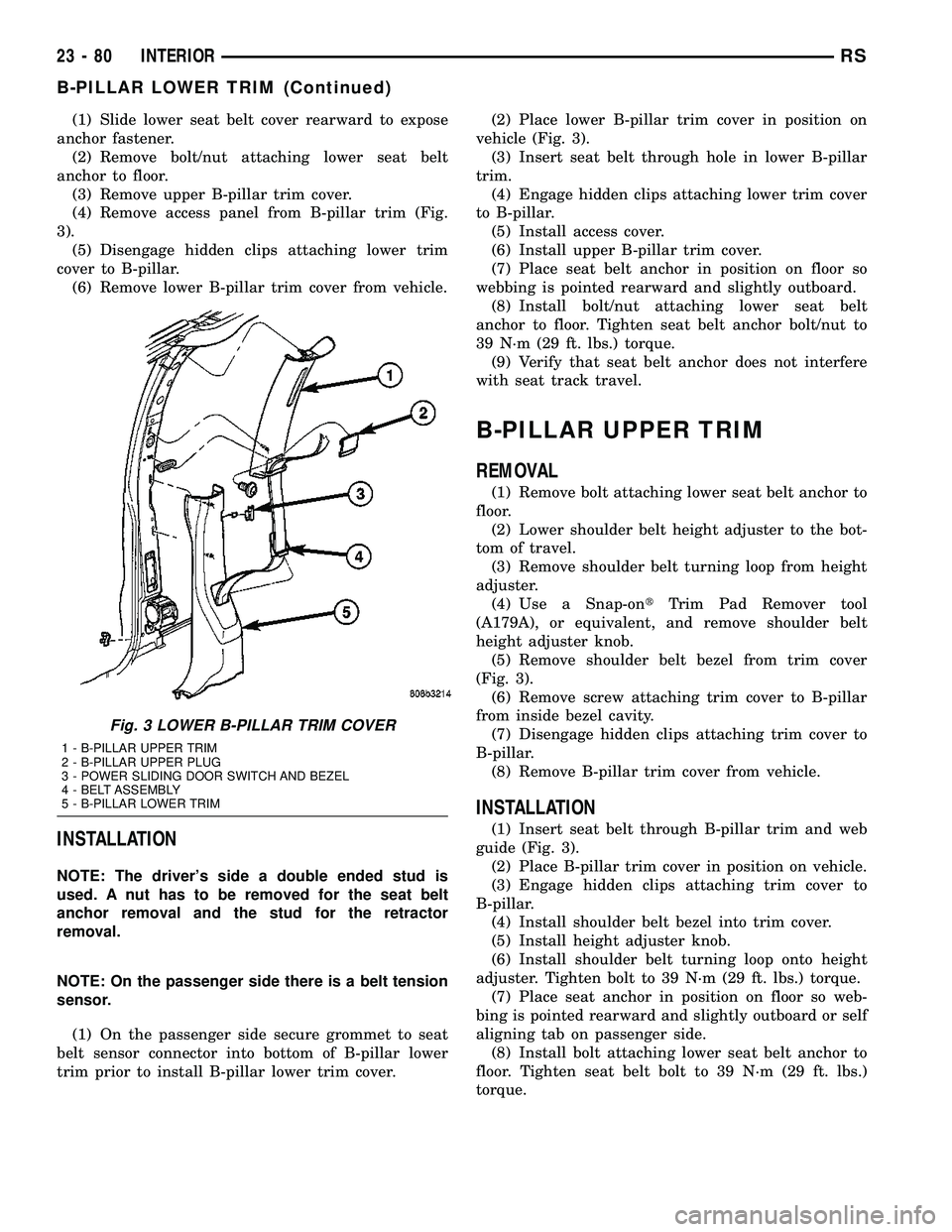
(1) Slide lower seat belt cover rearward to expose
anchor fastener.
(2) Remove bolt/nut attaching lower seat belt
anchor to floor.
(3) Remove upper B-pillar trim cover.
(4) Remove access panel from B-pillar trim (Fig.
3).
(5) Disengage hidden clips attaching lower trim
cover to B-pillar.
(6) Remove lower B-pillar trim cover from vehicle.
INSTALLATION
NOTE: The driver's side a double ended stud is
used. A nut has to be removed for the seat belt
anchor removal and the stud for the retractor
removal.
NOTE: On the passenger side there is a belt tension
sensor.
(1) On the passenger side secure grommet to seat
belt sensor connector into bottom of B-pillar lower
trim prior to install B-pillar lower trim cover.(2) Place lower B-pillar trim cover in position on
vehicle (Fig. 3).
(3) Insert seat belt through hole in lower B-pillar
trim.
(4) Engage hidden clips attaching lower trim cover
to B-pillar.
(5) Install access cover.
(6) Install upper B-pillar trim cover.
(7) Place seat belt anchor in position on floor so
webbing is pointed rearward and slightly outboard.
(8) Install bolt/nut attaching lower seat belt
anchor to floor. Tighten seat belt anchor bolt/nut to
39 N´m (29 ft. lbs.) torque.
(9) Verify that seat belt anchor does not interfere
with seat track travel.
B-PILLAR UPPER TRIM
REMOVAL
(1) Remove bolt attaching lower seat belt anchor to
floor.
(2) Lower shoulder belt height adjuster to the bot-
tom of travel.
(3) Remove shoulder belt turning loop from height
adjuster.
(4) Use a Snap-ontTrim Pad Remover tool
(A179A), or equivalent, and remove shoulder belt
height adjuster knob.
(5) Remove shoulder belt bezel from trim cover
(Fig. 3).
(6) Remove screw attaching trim cover to B-pillar
from inside bezel cavity.
(7) Disengage hidden clips attaching trim cover to
B-pillar.
(8) Remove B-pillar trim cover from vehicle.
INSTALLATION
(1) Insert seat belt through B-pillar trim and web
guide (Fig. 3).
(2) Place B-pillar trim cover in position on vehicle.
(3) Engage hidden clips attaching trim cover to
B-pillar.
(4) Install shoulder belt bezel into trim cover.
(5) Install height adjuster knob.
(6) Install shoulder belt turning loop onto height
adjuster. Tighten bolt to 39 N´m (29 ft. lbs.) torque.
(7) Place seat anchor in position on floor so web-
bing is pointed rearward and slightly outboard or self
aligning tab on passenger side.
(8) Install bolt attaching lower seat belt anchor to
floor. Tighten seat belt bolt to 39 N´m (29 ft. lbs.)
torque.
Fig. 3 LOWER B-PILLAR TRIM COVER
1 - B-PILLAR UPPER TRIM
2 - B-PILLAR UPPER PLUG
3 - POWER SLIDING DOOR SWITCH AND BEZEL
4 - BELT ASSEMBLY
5 - B-PILLAR LOWER TRIM
23 - 80 INTERIORRS
B-PILLAR LOWER TRIM (Continued)
Page 1879 of 2339
PAINT
TABLE OF CONTENTS
page page
PAINT
SPECIFICATIONS - COLOR CODE CHARTS . . 100
BASE COAT/CLEARCOAT FINISH
DESCRIPTION........................101
PAINT CODE
DESCRIPTION........................101PAINTED TOUCH-UP
DESCRIPTION........................101
FINESSE SANDING/BUFFING & POLISHING
DESCRIPTION........................101
PAINT
SPECIFICATIONS - COLOR CODE CHARTS
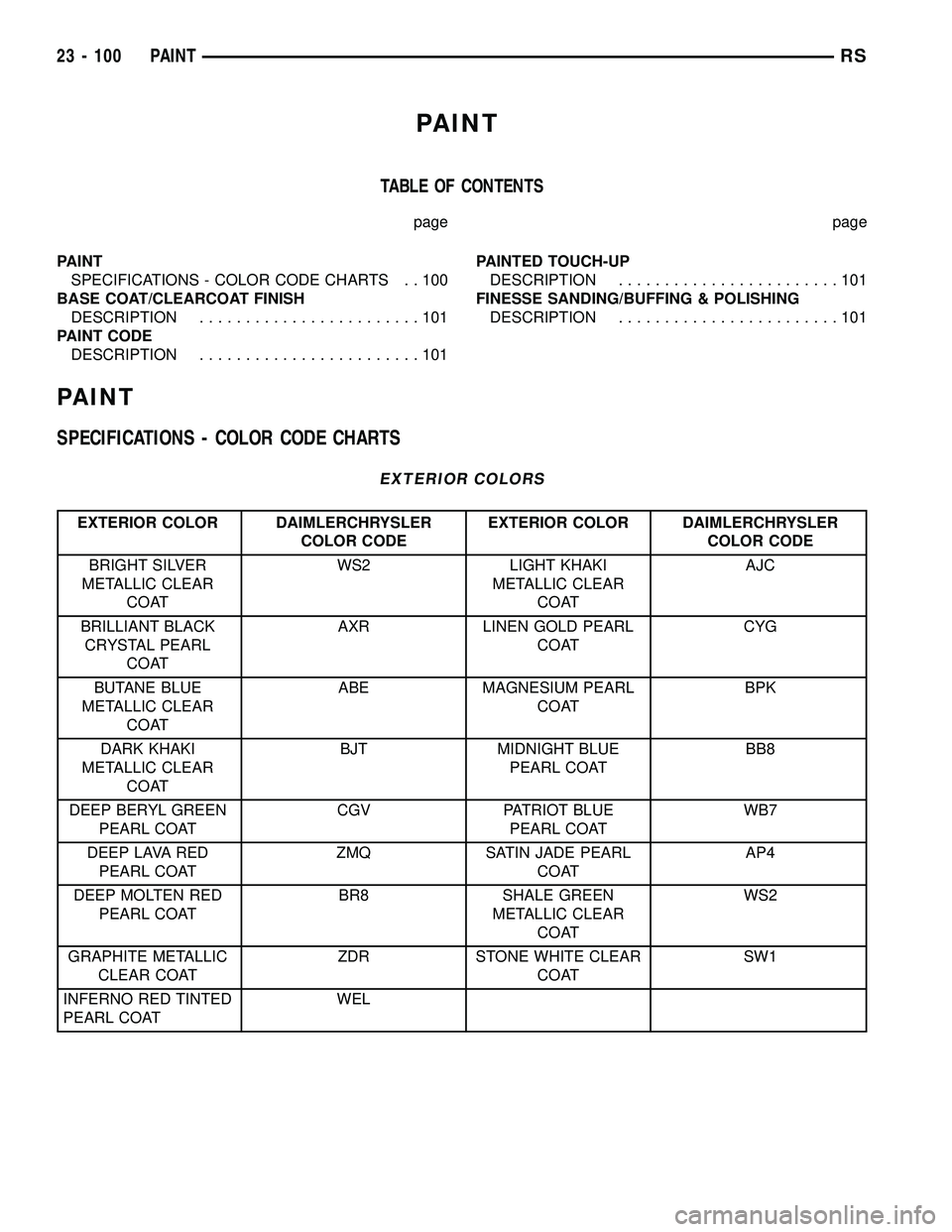
EXTERIOR COLORS
EXTERIOR COLOR DAIMLERCHRYSLER
COLOR CODEEXTERIOR COLOR DAIMLERCHRYSLER
COLOR CODE
BRIGHT SILVER
METALLIC CLEAR
COATWS2 LIGHT KHAKI
METALLIC CLEAR
COATAJC
BRILLIANT BLACK
CRYSTAL PEARL
COATAXR LINEN GOLD PEARL
COATCYG
BUTANE BLUE
METALLIC CLEAR
COATABE MAGNESIUM PEARL
COATBPK
DARK KHAKI
METALLIC CLEAR
COATBJT MIDNIGHT BLUE
PEARL COATBB8
DEEP BERYL GREEN
PEARL COATCGV PATRIOT BLUE
PEARL COATWB7
DEEP LAVA RED
PEARL COATZMQ SATIN JADE PEARL
COATAP4
DEEP MOLTEN RED
PEARL COATBR8 SHALE GREEN
METALLIC CLEAR
COATWS2
GRAPHITE METALLIC
CLEAR COATZDR STONE WHITE CLEAR
COATSW1
INFERNO RED TINTED
PEARL COATWEL
23 - 100 PAINTRS
Page 1880 of 2339
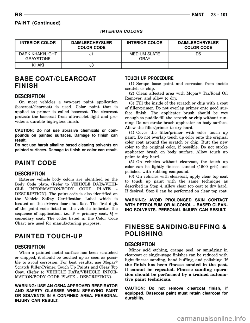
INTERIOR COLORS
INTERIOR COLOR DAIMLERCHRYSLER
COLOR CODEINTERIOR COLOR DAIMLERCHRYSLER
COLOR CODE
DARK KHAKI/LIGHT
GRAYSTONEJ1 MEDIUM SLATE
GRAYD5
KHAKI J3
BASE COAT/CLEARCOAT
FINISH
DESCRIPTION
On most vehicles a two-part paint application
(basecoat/clearcoat) is used. Color paint that is
applied to primer is called basecoat. The clearcoat
protects the basecoat from ultraviolet light and pro-
vides a durable high-gloss finish.
CAUTION: Do not use abrasive chemicals or com-
pounds on painted surfaces. Damage to finish can
result.
Do not use harsh alkaline based cleaning solvents on
painted surfaces. Damage to finish or color can result.
PAINT CODE
DESCRIPTION
Exterior vehicle body colors are identified on the
Body Code plate. (Refer to VEHICLE DATA/VEHI-
CLE INFORMATION/BODY CODE PLATE -
DESCRIPTION). The paint code is also identified on
the Vehicle Safety Certification Label which is
located on the drivers door shut face. The first digit
of the paint code listed on the vehicle indicates the
sequence of application, i.e.: P = primary coat, Q =
secondary coat. The codes listed in the Color Code
Chart are used for manufacturing purposes.
PAINTED TOUCH-UP
DESCRIPTION
When a painted metal surface has been scratched
or chipped, it should be touched up as soon as possi-
ble to avoid corrosion. For best results, use Mopart
Scratch Filler/Primer, Touch Up Paints and Clear Top
Coat. (Refer to VEHICLE DATA/VEHICLE INFOR-
MATION/BODY CODE PLATE - DESCRIPTION).
WARNING: USE AN OSHA APPROVED RESPIRATOR
AND SAFETY GLASSES WHEN SPRAYING PAINT
OR SOLVENTS IN A CONFINED AREA. PERSONAL
INJURY CAN RESULT.
TOUCH UP PROCEDURE
(1) Scrape loose paint and corrosion from inside
scratch or chip.
(2) Clean affected area with MopartTar/Road Oil
Remover, and allow to dry.
(3) Fill the inside of the scratch or chip with a coat
of filler/primer. Do not overlap primer onto good sur-
face finish. The applicator brush should be wet
enough to puddle-fill the scratch or chip without run-
ning. Do not stroke brush applicator on body surface.
Allow the filler/primer to dry hard.
(4) Cover the filler/primer with color touch up
paint. Do not overlap touch up color onto the original
color coat around the scratch or chip. Butt the new
color to the original color, if possible. Do not stroke
applicator brush on body surface. Allow touch up
paint to dry hard.
(5) On vehicles without clearcoat, the touch up
color can be lightly finesse sanded (1500 grit) and
polished with rubbing compound.
(6) On vehicles with clearcoat, apply clear top coat
to touch up paint with the same technique as
described in Step 4. Allow clear top coat to dry hard.
If desired, Step 5 can be performed on clear top coat.
WARNING: AVOID PROLONGED SKIN CONTACT
WITH PETROLEUM OR ALCOHOL ± BASED CLEAN-
ING SOLVENTS. PERSONAL INJURY CAN RESULT.
FINESSE SANDING/BUFFING &
POLISHING
DESCRIPTION
Minor acid etching, orange peel, or smudging in
clearcoat or single-stage finishes can be reduced with
light finesse sanding, hand buffing, and polishing.If
the finish has been finesse sanded in the past,
it cannot be repeated. Finesse sanding opera-
tion should be performed by a trained automo-
tive paint technician.
CAUTION: Do not remove clearcoat finish, if
equipped. Basecoat paint must retain clearcoat for
durability.
RSPAINT23 - 101
PAINT (Continued)
Page 2156 of 2339
MANUAL DUAL ZONE
²The two slide controls enable continuously vari-
able proportioning of the conditioned air.
²The mode control knob enables continuously
variable proportioning of air flow between modes and
has detents adjacent to each icon.
²The blower control provides four separate speeds
and an Off position.
²When the heater-A/C system is off, the HVAC
computer closes the recirculation door to prevent out-
side air from entering the passenger compartment.
²Interior air may be recirculated to speed up
heating or cooling in all modes except defrost and
mix by pressing the Recirculate button on the A/C-
heater control.
²To reduce humidity for rapid defogging, the A/C
compressor runs automatically in modes from ªmixº
to full defrost when outside temperatures are above
freezing.
²Air conditioning is available in any mode by
pressing the snowflake, A/C on/off button.
MANUAL THREE ZONE
FRONT CONTROL PANEL
²Primary control of the rear heater-A/C system is
on the instrument panel. This control allows the
driver to set the rear compartment fan speed, to turn
the rear heater-A/C system off, or to give control to
the intermediate seat occupants by switching to the
Rear position. When the rear heater-A/C system is
controlled from the instrument panel, rear air tem-
perature is based on the driver-side temperature con-
trol position, and the mode (floor or overhead air) is
based on the front control's mode position.
²The mode control knob enables continuously
variable proportioning of air flow between modes but
has detents adjacent to each icon.
²The blower control provides four separate speeds
and an Off position. When the heater-A/C system is
off, the HVAC computer closes the recirculation door
to prevent outside air from entering the passenger
compartment.
²Interior air may be recirculated to speed up
heating or cooling in all modes except defrost and
mix by pressing the Recirculate button on the control
panel.
²To reduce humidity for rapid defogging the A/C
compressor runs automatically in modes from ªmix'
to full defrost when outside temperatures are above
freezing.
²Air conditioning is available in any mode by
pressing the snowflake, A/C on/off, button.
REAR CONTROL PANEL
With the rear control active, temperature selection
dictates the air distribution mode (floor or overhead
air) of the rear unit: a cool temperature setting
directs flow to the overhead outlets and a warm tem-
perature setting to the floor.
AUTOMATIC TEMPERATURE CONTROL
Comfort temperature or perceived temperature is
affected by air flow, sun levels on exposed skin, etc.
The air temperature may be higher or lower than the
comfort temperature. The automatic temperature
control (ATC) system uses two infrared sensors in the
instrument panel center stack to measure the tem-
perature of the front occupants in order determine
their comfort level relative to their selected comfort
temperature. The integral HVAC computer adjusts
temperature and air flow rates to maintain the cus-
tomer-perceived comfort temperatures. The air tem-
perature in the passenger compartment may be
slightly higher or lower than the comfort tempera-
ture at any time. For instance, on sunny summer
days the air flow will probably be cooler than the
comfort temperature; on cold or cloudy days and at
night it will probably be slightly warmer.
The Three-Zone ATC system uses the infrared sen-
sors located in the instrument panel center stack
along with an offset calibration strategy to meet the
comfort requirements of the rear seat occupants.
FRONT CONTROL PANEL
²AUTO HI/LO± This system features two sets of
automatic control logic that allow either a rapid cool-
down rate or a somewhat slower cool-down rate with
less fan noise. HI-AUTO controls the system to reach
its assigned temperature quickly with a higher fan
speed. LO-AUTO controls the system to reach its
assigned temperature somewhat slower with less fan
noise. Both modes will automatically engage auto
recirculation.
²DEFROST± The defrost function must be man-
ually selected to direct air flow to the windshield to
remove fog or ice. The ATC system cannot automati-
cally sense the presence of fog or ice on the wind-
shield.
²RECIRC± The RECIRC button will close the
air inlet door. If the system is in auto recirc (indica-
tor being displayed automatically), pressing the man-
ual recirc button will disable the auto recirc function
until one of the auto keys are pressed or the ignition
is cycled. If Auto HI/LO is pressed while manual
recirc is active, manual recirc will be deactivated.
²REAR WINDOW DEFOGGER± Pushing the
button sends a PCI bus message to the intelligent
power module which controls the rear window defog-
ger and side view mirror (if equipped) circuitry. The
RSHEATING & AIR CONDITIONING24-5
HEATING & AIR CONDITIONING (Continued)