2005 CHRYSLER CARAVAN light
[x] Cancel search: lightPage 2191 of 2339
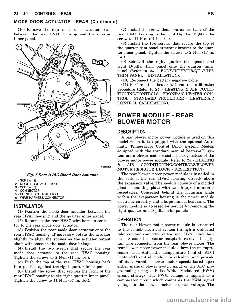
(10) Remove the rear mode door actuator from
between the rear HVAC housing and the quarter
inner panel.
INSTALLATION
(1) Position the mode door actuator between the
rear HVAC housing and the quarter inner panel.
(2) Reconnect the rear HVAC wire harness connec-
tor to the rear mode door actuator.
(3) Position the rear mode door actuator onto the
rear HVAC housing. If necessary, rotate the actuator
slightly to align the splines on the actuator output
shaft with those in the mode door linkage.
(4) Install the two screws that secure the rear
mode door actuator to the rear HVAC housing.
Tighten the screws to 2 N´m (17 in. lbs.).
(5) Push the top of the rear HVAC housing back
into position against the right quarter inner panel.
(6) Install the screw that secures the front of the
rear HVAC housing to the right quarter inner panel.
Tighten the screw to 11 N´m (97 in. lbs.).(7) Install the screw that secures the back of the
rear HVAC housing to the right D-pillar. Tighten the
screw to 11 N´m (97 in. lbs.).
(8) Install the two screws that secure the top of
the quarter trim panel attaching bracket to the quar-
ter inner panel. Tighten the screws to 2 N´m (17 in.
lbs.).
(9) Reinstall the right quarter trim panel and
right D-pillar trim panel onto the quarter inner
panel (Refer to 23 - BODY/INTERIOR/QUARTER
TRIM PANEL - INSTALLATION).
(10) Reconnect the battery negative cable.
(11) Perform the heater-A/C control calibration
procedure (Refer to 24 - HEATING & AIR CONDI-
TIONING/CONTROLS - FRONT/A/C-HEATER CON-
TROL - STANDARD PROCEDURE - HEATER-A/C
CONTROL CALIBRATION).
POWER MODULE - REAR
BLOWER MOTOR
DESCRIPTION
A rear blower motor power module is used on this
model when it is equipped with the optional Auto-
matic Temperature Control (ATC) system. Models
equipped with the standard manual heater-A/C sys-
tem use a blower motor resistor block , instead of the
blower motor power module (Refer to 24 - HEATING
& AIR CONDITIONING/CONTROLS/BLOWER
MOTOR RESISTOR BLOCK - DESCRIPTION).
The rear blower motor power module is installed in
the back of the rear HVAC housing, directly above
the expansion valve. The module consists of a molded
plastic mounting plate with two integral connector
receptacles. Concealed behind the mounting plate
within the evaporator housing is the power module
electronic circuitry and a large finned, heat sink. The
power module is accessed for service by removing the
right quarter and D-pillar trim panels.
OPERATION
The rear blower motor power module is connected
to the vehicle electrical system through a dedicated
take out and connector of the rear HVAC wire har-
ness. A second connector receptacle receives the pig-
tail wire connector from the rear blower motor. The
rear blower motor power module allows the micropro-
cessor-based Automatic Temperature Control (ATC)
heater-A/C control module to calculate and provide
infinitely variable blower motor speeds based upon
either manual blower switch input or the ATC pro-
gramming using a Pulse Width Modulated (PWM)
circuit strategy. The PWM voltage is applied to a
comparator circuit which compares the PWM signal
voltage to the blower motor feedback voltage. The
Fig. 7 Rear HVAC Blend Door Actuator
1 - SCREW (2)
2 - MODE DOOR ACTUATOR
3 - SCREW (2)
4 - CONNECTOR
5 - BLEND DOOR ACTUATOR
6 - WIRE HARNESS CONNECTOR
24 - 40 CONTROLS - REARRS
MODE DOOR ACTUATOR - REAR (Continued)
Page 2216 of 2339
PLUMBING - FRONT
DESCRIPTION
CAUTION: The system must be completely empty
before opening any fitting or connection in the
refrigeration system. Open fittings with caution
even after the system has been emptied. If any
pressure is noticed as a fitting is loosened,
retighten fitting and evacuate the system again.
The use of correct wrenches when making connec-
tions is very important. Improper wrenches or
improper use of wrenches can damage the fittings.
The internal parts of the A/C system will remain sta-
ble as long as moisture-free refrigerant and refrig-
erant oil is used. Abnormal amounts of dirt,
moisture or air can upset the chemical stability.
This may cause operational troubles or even seri-
ous damage if present in more than very small
quantities. Before disconnecting a refrigerant line
or hose, clean the outside of the fittings thoroughly
to prevent contamination from entering the refriger-
ant system.
When opening a refrigeration system, have every-
thing you will need to repair the system ready to
minimize the amount of time the system is opened.
Cap or plug all refrigerant line fittings as soon as
they are opened. This will help prevent the entrance
of dirt and moisture. All new lines and components
should be capped or sealed until they are ready to
be used. Before connecting a refrigerant line or
hose, clean the outside of the fittings thoroughly to
prevent contamination from entering the refrigerant
system.
All tools, including the refrigerant dispensing mani-
fold, manifold gauge set and test hoses should be
kept clean and dry.
The A/C refrigerant lines and hoses are used to
carry the refrigerant between the various A/C system
components. The refrigerant lines and hoses for the
R-134a system on this vehicle consist of a barrier-
hose design with a nylon tube sandwiched between
rubber layers. The nylon tube helps to contain the
R-134a refrigerant, which has a smaller molecular
structure than R-12 refrigerant. The ends of the
refrigerant lines are made from lightweight alumi-
num or steel, and commonly use braze-less fittings.Any kinks or sharp bends in the refrigerant lines
and hoses will reduce the capacity of the entire A/C
system and can reduce the flow of refrigerant in the
system. The radius of all bends in the flexible hose
refrigerant lines should be at least ten times the
diameter of the hose and the refrigerant lines should
be routed so they are at least 80 millimeters (3
inches) away from the exhaust manifold(s) and
exhaust pipe(s).
OPERATION
High pressures are produced in the refrigerant sys-
tem when the A/C compressor is operating. Extreme
care must be exercised to make sure that each of the
refrigerant system connections is pressure-tight and
leak free. It is a good practice to inspect all flexible
hose refrigerant lines at least once a year to make
sure they are in good condition and properly routed.
The refrigerant lines and hoses are coupled to
other A/C system components with block-type fit-
tings. An O-ring seal, or a flat steel gasket with an
integral O-ring (dual plane seal), is used to mate the
refrigerant line fittings with A/C system components
to ensure the integrity of the refrigerant system.
The refrigerant lines and hoses cannot be repaired
and, if faulty or damaged, they must be replaced.
WARNING
ENGINE COOLING SYSTEM
WARNING: THE ENGINE COOLING SYSTEM IS
DESIGNED TO DEVELOP INTERNAL PRESSURES
OF 97 TO 123 KILOPASCALS (14 TO 18 POUNDS
PER SQUARE INCH). DO NOT REMOVE OR
LOOSEN THE COOLANT PRESSURE CAP, CYLIN-
DER BLOCK DRAIN PLUGS, RADIATOR DRAIN,
RADIATOR HOSES, HEATER HOSES, OR HOSE
CLAMPS WHILE THE ENGINE COOLING SYSTEM IS
HOT AND UNDER PRESSURE. FAILURE TO
OBSERVE THIS WARNING CAN RESULT IN SERI-
OUS BURNS FROM THE HEATED ENGINE COOL-
ANT. ALLOW THE VEHICLE TO COOL FOR A
MINIMUM OF 15 MINUTES BEFORE OPENING THE
COOLING SYSTEM FOR SERVICE.
RSPLUMBING - FRONT24-65
Page 2235 of 2339
heater core inlet and outlet ports. Removable heater
core tubes attach to the ports by use of a sealing
plate secured with a screw to the heater core tank.
This removable heater core tube arrangement allows
the heater core to be serviced without removing the
HVAC housing from the vehicle.
OPERATION
Engine coolant is circulated through heater hoses
to the heater core at all times. As the coolant flows
through the heater core, heat removed from the
engine is transferred to the heater core fins and
tubes. Air directed through the heater core picks up
the heat from the heater core fins. The blend door
allows control of the heater output air temperature
by regulating the amount of air that is flowing
through the heater core within the HVAC housing.
The heater core cannot be repaired and, if faulty or
damaged, it must be replaced.
REMOVAL
FRONT HEATER CORE TUBES
WARNING: ON VEHICLES EQUIPPED WITH AIR-
BAGS, DISABLE THE AIRBAG SYSTEM BEFORE
ATTEMPTING ANY STEERING WHEEL, STEERING
COLUMN, OR INSTRUMENT PANEL COMPONENT
DIAGNOSIS OR SERVICE. DISCONNECT AND ISO-
LATE THE BATTERY NEGATIVE (GROUND) CABLE,
THEN WAIT TWO MINUTES FOR THE AIRBAG SYS-
TEM CAPACITOR TO DISCHARGE BEFORE PER-
FORMING FURTHER DIAGNOSIS OR SERVICE. THIS
IS THE ONLY SURE WAY TO DISABLE THE AIRBAG
SYSTEM. FAILURE TO TAKE THE PROPER PRE-
CAUTIONS COULD RESULT IN ACCIDENTAL AIR-
BAG DEPLOYMENT AND POSSIBLE PERSONAL
INJURY.
(1) Drain the engine cooling system (Refer to 7 -
COOLING - STANDARD PROCEDURE - COOLING
SYSTEM DRAIN).
(2) Disconnect and isolate the battery negative
cable.
(3) Disconnect the heater hoses from the heater
core tubes (Refer to 24 - HEATING & AIR CONDI-
TIONING/PLUMBING/HEATER INLET HOSE -
REMOVAL) and (Refer to 24 - HEATING & AIR
CONDITIONING/PLUMBING/HEATER RETURN
HOSE - REMOVAL).(4) Remove the silencer from beneath the driver
side end of the instrument panel.
NOTE: Take the proper precautions to protect the
carpeting below the heater core from spilled engine
coolant and have absorbent toweling readily avail-
able to clean up any spills.
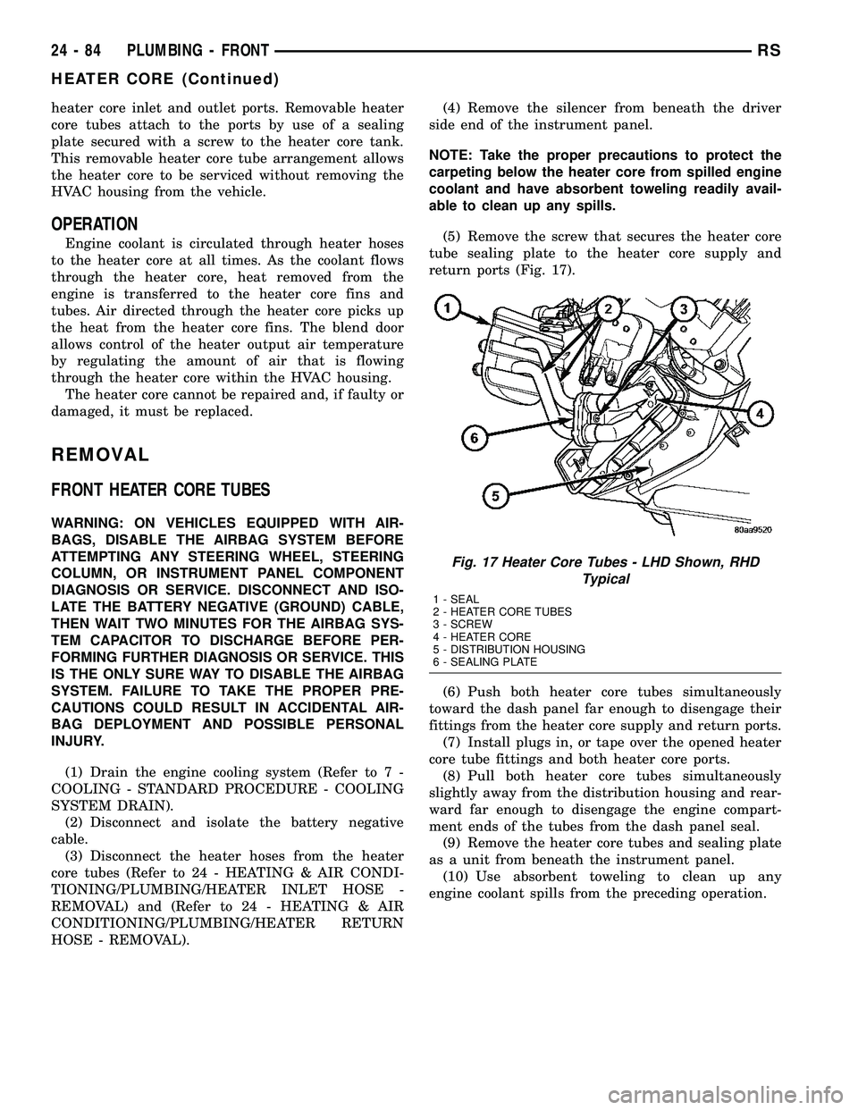
(5) Remove the screw that secures the heater core
tube sealing plate to the heater core supply and
return ports (Fig. 17).
(6) Push both heater core tubes simultaneously
toward the dash panel far enough to disengage their
fittings from the heater core supply and return ports.
(7) Install plugs in, or tape over the opened heater
core tube fittings and both heater core ports.
(8) Pull both heater core tubes simultaneously
slightly away from the distribution housing and rear-
ward far enough to disengage the engine compart-
ment ends of the tubes from the dash panel seal.
(9) Remove the heater core tubes and sealing plate
as a unit from beneath the instrument panel.
(10) Use absorbent toweling to clean up any
engine coolant spills from the preceding operation.
Fig. 17 Heater Core Tubes - LHD Shown, RHD
Typical
1 - SEAL
2 - HEATER CORE TUBES
3 - SCREW
4 - HEATER CORE
5 - DISTRIBUTION HOUSING
6 - SEALING PLATE
24 - 84 PLUMBING - FRONTRS
HEATER CORE (Continued)
Page 2236 of 2339
FRONT HEATER CORE
WARNING: ON VEHICLES EQUIPPED WITH AIR-
BAGS, DISABLE THE AIRBAG SYSTEM BEFORE
ATTEMPTING ANY STEERING WHEEL, STEERING
COLUMN, OR INSTRUMENT PANEL COMPONENT
DIAGNOSIS OR SERVICE. DISCONNECT AND ISO-
LATE THE BATTERY NEGATIVE (GROUND) CABLE,
THEN WAIT TWO MINUTES FOR THE AIRBAG SYS-
TEM CAPACITOR TO DISCHARGE BEFORE PER-
FORMING FURTHER DIAGNOSIS OR SERVICE. THIS
IS THE ONLY SURE WAY TO DISABLE THE AIRBAG
SYSTEM. FAILURE TO TAKE THE PROPER PRE-
CAUTIONS COULD RESULT IN ACCIDENTAL AIR-
BAG DEPLOYMENT AND POSSIBLE PERSONAL
INJURY.
(1) Remove the silencer boot fasteners located
around the base of the lower steering shaft from the
dash panel so that it may be pushed aside.
(2) Remove the brake lamp switch from its mount-
ing bracket (Refer to 8 - ELECTRICAL/LAMPS/
LIGHTING - EXTERIOR/BRAKE LAMP SWITCH -
REMOVAL).
(3) Disconnect the power brake booster input rod
(push rod) from the pin on the brake pedal arm
(Refer to 5 - BRAKES - ABS/HYDRAULIC/ME-
CHANICAL/POWER BRAKE BOOSTER -
REMOVAL).
(4) Remove the heater core tubes (Refer to 24 -
HEATING & AIR CONDITIONING/PLUMBING/
HEATER CORE - REMOVAL).
(5) Remove the two screws that secure the heater
core mounting plate to the distribution housing.
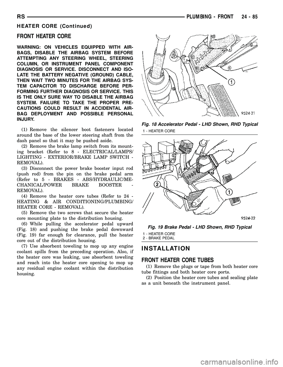
(6) While pulling the accelerator pedal upward
(Fig. 18) and pushing the brake pedal downward
(Fig. 19) far enough for clearance, pull the heater
core out of the distribution housing.
(7) Use absorbent toweling to mop up any engine
coolant spills from the preceding operation. Also, if
the heater core was leaking, use absorbent toweling
and reach into the heater core opening to mop up
any residual engine coolant within the distribution
housing.
INSTALLATION
FRONT HEATER CORE TUBES
(1) Remove the plugs or tape from both heater core
tube fittings and both heater core ports.
(2) Position the heater core tubes and sealing plate
as a unit beneath the instrument panel.
Fig. 18 Accelerator Pedal - LHD Shown, RHD Typical
1 - HEATER CORE
Fig. 19 Brake Pedal - LHD Shown, RHD Typical
1 - HEATER CORE
2 - BRAKE PEDAL
RSPLUMBING - FRONT24-85
HEATER CORE (Continued)
Page 2237 of 2339
(3) Align the engine compartment ends of both
heater core tubes with the openings in the dash
panel seal and push them simultaneously forward
through the seal far enough to engage the heater
core ends of the tubes with the heater core supply
and return ports.
(4) Position both heater core tubes and the sealing
plate simultaneously to the heater core supply and
return ports.
NOTE: The heater core tubes each have a slot that
must be indexed to a location tab within each of the
heater core ports. Adjust the position of the tubes
as required so that the sealing plate fits flush
against the heater core supply and return ports,
which indicates that the tubes are properly indexed.
(5) Index both heater core tubes to the heater core
ports.
(6) Install the screw that secures the heater core
tube sealing plate to the heater core supply and
return ports. Tighten the screw to 3 N´m (27 in. lbs.).
(7) Install the silencer under the driver side end of
the instrument panel.
(8) Connect the heater hoses to the heater hose
tubes (Refer to 24 - HEATING & AIR CONDITION-
ING/PLUMBING/HEATER INLET HOSE - INSTAL-
LATION) and(Refer to 24 - HEATING & AIR
CONDITIONING/PLUMBING/HEATER RETURN
HOSE - INSTALLATION).
(9) Reconnect the battery negative cable.
(10) Refill the engine cooling system (Refer to 7 -
COOLING - STANDARD PROCEDURE - COOLING
SYSTEM REFILL).
FRONT HEATER CORE
(1) While pushing the brake pedal downward and
pulling the accelerator pedal upward far enough for
clearance, slide the heater core into the distribution
housing.
(2) Install the two screws that secure the heater
core mounting plate to the distribution housing.
Tighten the screws to 2 N´m (17 in. lbs.).(3) Install the heater core tubes (Refer to 24 -
HEATING & AIR CONDITIONING/PLUMBING/
HEATER CORE - INSTALLATION).
(4) Reconnect the power brake booster input rod
(push rod) to the pin on the brake pedal arm (Refer
to 5 - BRAKES/HYDRAULIC/MECHANICAL/
POWER BRAKE BOOSTER - INSTALLATION).
(5) Reinstall the brake lamp switch into its mount-
ing bracket (Refer to 8 - ELECTRICAL/LAMPS/
LIGHTING - EXTERIOR/BRAKE LAMP SWITCH -
INSTALLATION).
(6) Reinstall the silencer boot around the base of
the lower steering shaft on the dash panel.
(7) Reconnect the battery negative cable.
(8) Refill the engine cooling system (Refer to 7 -
COOLING - STANDARD PROCEDURE - COOLING
SYSTEM REFILL).
(9) Operate system for two thermostat cycles to
assure the elimination of any air that may be
trapped within the cooling system.
HEATER INLET HOSE
REMOVAL
WARNING: REFER TO THE APPLICABLE WARN-
INGS AND CAUTIONS FOR THIS SYSTEM BEFORE
PERFORMING THE FOLLOWING OPERATION (Refer
to 24 - HEATING & AIR CONDITIONING/PLUMBING -
WARNING).
NOTE: The heater inlet hose is constructed from
formed steel tubing and rubber hoses. Depending
on application, the ends are secured to the heater
core, engine oil cooler or the engine by spring ten-
sion clamps.
(1) Drain the engine cooling system (Refer to 7 -
COOLING - STANDARD PROCEDURE - COOLING
SYSTEM DRAIN).
24 - 86 PLUMBING - FRONTRS
HEATER CORE (Continued)
Page 2292 of 2339
(2) Install hose on PCV valve. Remove the
make-up air hose from the air plenum at the rear of
the engine. Hold a piece of stiff paper (parts tag)
loosely over the end of the make-up air hose.
(3) After allowing approximately one minute for
crankcase pressure to reduce, the paper should draw
up against the hose with noticeable force. If the
engine does not draw the paper against the grommet
after installing a new valve, replace the PCV valve
hose.
(4) Turn the engine off. Remove the PCV valve
from intake manifold. The valve should rattle when
shaken.
(5) Replace the PCV valve and retest the system if
it does not operate as described in the preceding
tests.Do not attempt to clean the old PCV valve.
If the valve rattles, apply a light coating of Loctitet
Pipe Sealant With Teflon to the threads. Thread the
PCV valve into the manifold plenum and tighten to 7
N´m (60 in. lbs.) torque.
VAPOR CANISTER
DESCRIPTION
There are 2 EVAP canisters on the vehicle. The
vacuum and vapor tubes connect to the top of the
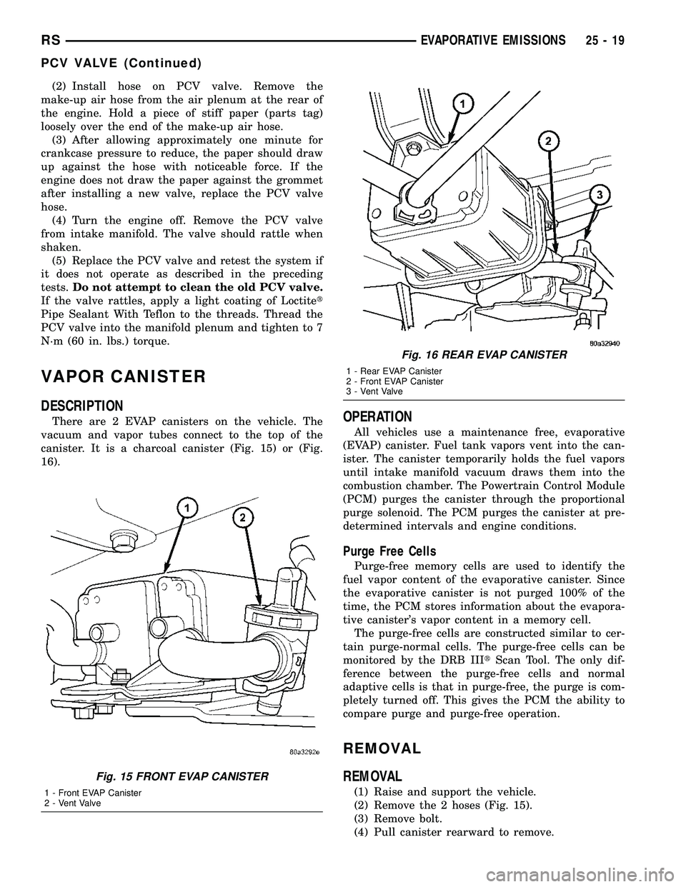
canister. It is a charcoal canister (Fig. 15) or (Fig.
16).OPERATION
All vehicles use a maintenance free, evaporative
(EVAP) canister. Fuel tank vapors vent into the can-
ister. The canister temporarily holds the fuel vapors
until intake manifold vacuum draws them into the
combustion chamber. The Powertrain Control Module
(PCM) purges the canister through the proportional
purge solenoid. The PCM purges the canister at pre-
determined intervals and engine conditions.
Purge Free Cells
Purge-free memory cells are used to identify the
fuel vapor content of the evaporative canister. Since
the evaporative canister is not purged 100% of the
time, the PCM stores information about the evapora-
tive canister's vapor content in a memory cell.
The purge-free cells are constructed similar to cer-
tain purge-normal cells. The purge-free cells can be
monitored by the DRB IIItScan Tool. The only dif-
ference between the purge-free cells and normal
adaptive cells is that in purge-free, the purge is com-
pletely turned off. This gives the PCM the ability to
compare purge and purge-free operation.
REMOVAL
REMOVAL
(1) Raise and support the vehicle.
(2) Remove the 2 hoses (Fig. 15).
(3) Remove bolt.
(4) Pull canister rearward to remove.
Fig. 15 FRONT EVAP CANISTER
1 - Front EVAP Canister
2 - Vent Valve
Fig. 16 REAR EVAP CANISTER
1 - Rear EVAP Canister
2 - Front EVAP Canister
3 - Vent Valve
RSEVAPORATIVE EMISSIONS25-19
PCV VALVE (Continued)
Page 2304 of 2339
BACKLIGHT (EBL) SYSTEM, DIAGNOSISAND TESTING - ELECTRIC ..............8G-2
BACKSTOW STRAP - THIRD ROW - FOLD-IN-FLOOR - INSTALLATION, SEAT . . 23-158
BACKSTOW STRAP - THIRD ROW - FOLD-IN-FLOOR - REMOVAL, SEAT ......23-158
BAG RETAINER - INSTALLATION, PLASTIC GROCERY .................. 23-149
BAG RETAINER - REMOVAL, PLASTIC GROCERY ......................... 23-149
BALANCE - STANDARD PROCEDURE, TIRE AND WHEEL ..................... 22-5
BALANCE SHAFTS AND CARRIER ASSEMBLY - DESCRIPTION .............9-71
BALANCE SHAFTS AND CARRIER ASSEMBLY - INSTALLATION .............9-73
BALANCE SHAFTS AND CARRIER ASSEMBLY - OPERATION ...............9-71
BALANCE SHAFTS AND CARRIER ASSEMBLY - REMOVAL .................9-71
BALL JOINT - DESCRIPTION, LOWER ......2-10
BALL JOINT - DIAGNOSIS AND TESTING, LOWER ............................. 2-10
BALL JOINT - OPERATION, LOWER .......2-10
BAR - DESCRIPTION, STABILIZER ....2-16,2-44
BAR - DESCRIPTION, TRACK ............2-45
BAR - INSPECTION, STABILIZER ..........2-17
BAR - INSTALLATION, STABILIZER ........2-17
BAR - INSTALLATION, TRACK ............2-46
BAR - OPERATION, STABILIZER ......2-16,2-44
BAR - OPERATION, TRACK ................2-46
BAR - REMOVAL, STABILIZER ...........2-17
BAR - REMOVAL, TRACK ...............2-46
BAR CUSHION - INSTALLATION, STABILIZER ...........................2-4
BAR CUSHION - REMOVAL, STABILIZER ....2-4
BASE BRAKE BLEEDING - STANDARD PROCEDURE ..........................5-8
BASE BRAKE SYSTEM - DIAGNOSIS AND TESTING .............................5-4
BASE BRAKE SYSTEM, SPECIAL TOOLS ....5-10
BASE BRAKES - DESCRIPTION ............5-3
BASE BRAKES - OPERATION ..............5-3
BASE BRAKES (EXPORT) - DESCRIPTION . . . 5-3
BASE COAT/CLEARCOAT FINISH - DESCRIPTION ...................... 23-101
BASE RISER - SECOND ROW - FOLD-IN-FLOOR - INSTALLATION, SEAT . . 23-135
BASE RISER - SECOND ROW - FOLD-IN-FLOOR - REMOVAL, SEAT ......23-134
BASE TRAY - INSTALLATION, FLOOR CONSOLE ........................... 23-89
BASE TRAY - REMOVAL, FLOOR CONSOLE ........................... 23-89
BATTERY - DESCRIPTION ...............8F-7
BATTERY - OPERATION .................8F-9
BATTERY - REMOVAL .................8F-16
BATTERY - SPECIFICATIONS ............8N-24
BATTERY CABLES - DESCRIPTION .......8F-16
BATTERY CABLES - OPERATION .........8F-17
BATTERY CABLES, DIAGNOSIS AND TESTING ........................... 8F-17
BATTERY CHARGING, STANDARD PROCEDURE - CONVENTIONAL ..........8F-11
BATTERY CHARGING, STANDARD PROCEDURE - SPIRAL PLATE ...........8F-10
BATTERY, DIAGNOSIS AND TESTING ......8F-9
BATTERY ELECTROLYTE LEVEL, STANDARD PROCEDURE - CHECKING ....8F-14
BATTERY HOLDDOWN - INSTALLATION . . . 8F-16
BATTERY HOLDDOWN - REMOVAL .......8F-16
BATTERY REPLACEMENT - STANDARD PROCEDURE ........................ 8N-24
BATTERY, SPECIFICATIONS ..............8F-6
BATTERY SYSTEM - DESCRIPTION ........8F-1
BATTERY SYSTEM - OPERATION .........8F-2
BATTERY SYSTEM, DIAGNOSIS AND TESTING ............................ 8F-2
BATTERY SYSTEM SPECIAL TOOLS, SPECIAL TOOLS ...................... 8F-7
BATTERY TEMPERATURE SENSOR - DESCRIPTION ....................... 8F-24
BATTERY TEMPERATURE SENSOR - OPERATION ......................... 8F-24
BATTERY TEMPERATURE SENSOR - REMOVAL .......................... 8F-24
BATTERY TEMPERATURE SENSOR - SPECIFICATIONS ..................... 8F-23BATTERY TESTER, STANDARD
PROCEDURE - MICRO 420 .............8F-15
BATTERY TRAY - DESCRIPTION .........8F-19
BATTERY TRAY - INSTALLATION .........8F-20
BATTERY TRAY - REMOVAL ............8F-19
BEARING - DESCRIPTION, HUB .......2-30,2-5
BEARING - DIAGNOSIS AND TESTING, HUB............................. 2-31,2-5
BEARING - INSTALLATION, HUB .......2-33,2-5
BEARING - OPERATION, HUB .........2-30,2-5
BEARING - REMOVAL, HUB ..........2-31,2-5
BEARING CLEARANCE - STANDARD PROCEDURE, MEASURING
CONNECTING ROD ................... 9-123
BEARING CLEARANCE USING PLASTIGAGE - STANDARD
PROCEDURE, MEASURING ..........9-12,9-86
BEARING FITTING - STANDARD PROCEDURE, MAIN ................... 9-125
BEARING PRELOAD - ADJUSTMENT, DIFFERENTIAL ...................... 21-228
BEARING PRELOAD MEASUREMENT AND ADJUSTMENT, ADJUSTMENTS -
DIFFERENTIAL ....................... 21-79
BEARINGS - INSTALLATION, CRANKSHAFT MAIN .................. 9-127
BEARINGS - REMOVAL, CRANKSHAFT MAIN .............................. 9-127
BEARINGS (IN BLOCK) - DESCRIPTION, CAMSHAFT ......................... 9-118
BEARINGS (IN BLOCK) - INSPECTION, CAMSHAFT ......................... 9-118
BEARINGS (IN BLOCK) - INSTALLATION, CAMSHAFT ......................... 9-118
BEARINGS (IN BLOCK) - OPERATION, CAMSHAFT ......................... 9-118
BEARINGS (IN BLOCK) - REMOVAL, CAMSHAFT ......................... 9-118
BELLCRANK - INSTALLATION ...........23-35
BELLCRANK - REMOVAL ...............23-35
BELT - DIAGNOSIS AND TESTING, ACCESSORY DRIVE .....................7-7
BELT - FOLD-IN-FLOOR - INSTALLATION, SEAT BELT CENTER LAP ..............23-157
BELT - FOLD-IN-FLOOR - REMOVAL, SEAT BELT CENTER LAP ..............23-157
BELT - INSTALLATION, TIMING ...........9-67
BELT - REMOVAL, TIMING ..............9-65
BELT & RETRACTOR - FIRST ROW - OUTBOARD - INSTALLATION, SEAT ......8O-40
BELT & RETRACTOR - FIRST ROW - OUTBOARD - REMOVAL, SEAT ..........8O-39
BELT & RETRACTOR - OUTBOARD - FRONT - INSTALLATION, SEAT ..........8O-39
BELT & RETRACTOR - OUTBOARD - FRONT - REMOVAL, SEAT ..............8O-38
BELT & RETRACTOR - SECOND ROW - LEFT OUTBOARD - INSTALLATION,
SEAT .............................. 8O-42
BELT & RETRACTOR - SECOND ROW - LEFT OUTBOARD - REMOVAL, SEAT .....8O-42
BELT & RETRACTOR - SECOND ROW - RIGHT OUTBOARD - INSTALLATION,
SEAT .............................. 8O-40
BELT & RETRACTOR - SECOND ROW - RIGHT OUTBOARD - REMOVAL, SEAT ....8O-40
BELT & RETRACTOR - SECOND ROW - RIGHT OUTBOARD WITH REAR HVAC -
LWB - INSTALLATION, SEAT ............8O-41
BELT & RETRACTOR - SECOND ROW - RIGHT OUTBOARD WITH REAR HVAC -
LWB - REMOVAL, SEAT ...............8O-41
BELT BUCKLE - FIRST ROW - BENCH - INSTALLATION, SEAT .................8O-37
BELT BUCKLE - FIRST ROW - BENCH - REMOVAL, SEAT ..................... 8O-36
BELT BUCKLE - FIRST ROW INBOARD - QUAD BUCKET - INSTALLATION, SEAT ....8O-36
BELT BUCKLE - FIRST ROW INBOARD - QUAD BUCKET - REMOVAL, SEAT .......8O-35
BELT BUCKLE - FRONT INBOARD - INSTALLATION, SEAT .................8O-35
BELT BUCKLE - FRONT INBOARD - REMOVAL, SEAT ..................... 8O-35
BELT BUCKLE - SECOND ROW - THREE PASSENGER BENCH - INSTALLATION,
SEAT .............................. 8O-40BELT BUCKLE - SECOND ROW - THREE
PASSENGER BENCH - REMOVAL, SEAT . . . 8O-40
BELT BUCKLE - SECOND ROW INBOARD - 50/50 BENCH - INSTALLATION, SEAT . . . 8O-38
BELT BUCKLE - SECOND ROW INBOARD - 50/50 BENCH - REMOVAL, SEAT .......8O-37
BELT CENTER LAP BELT - FOLD-IN- FLOOR - INSTALLATION, SEAT .........23-157
BELT CENTER LAP BELT - FOLD-IN- FLOOR - REMOVAL, SEAT .............23-157
BELT COVER(S) - INSTALLATION, TIMING ............................. 9-64
BELT COVER(S) - REMOVAL, TIMING ......9-63
BELT HEIGHT ADJUSTE R-BOR
C-PILLAR - INSTALLATION, SEAT ........8O-38
BELT HEIGHT ADJUSTE R-BOR
C-PILLAR - REMOVAL, SEAT ...........8O-38
BELT HEIGHT ADJUSTER KNOB - INSTALLATION, SEAT .................8O-38
BELT HEIGHT ADJUSTER KNOB - REMOVAL, SEAT ..................... 8O-38
BELT MOLDING - INSTALLATION, FRONT DOOR INNER ....................... 23-168
BELT MOLDING - INSTALLATION, FRONT DOOR OUTER ...................... 23-167
BELT MOLDING - REMOVAL, FRONT DOOR INNER ....................... 23-168
BELT MOLDING - REMOVAL, FRONT DOOR OUTER ...................... 23-167
BELT TENSION - STANDARD PROCEDURE, CHECKING POWER
STEERING ............................7-8
BELT TENSION SENSOR - DESCRIPTION . . . 8O-8
BELT TENSION SENSOR - OPERATION .....8O-9
BELT TENSION, SPECIFICATIONS - ACCESSORY DRIVE .....................7-5
BELT TENSIONER - 2.4L - INSTALLATION . . 7-11
BELT TENSIONER - 2.4L - REMOVAL ......7-11
BELT TENSIONER - 3.3/3.8L - INSTALLATION ........................ 7-12
BELT TENSIONER - 3.3/3.8L - REMOVAL . . . 7-12
BELT TENSIONER - DESCRIPTION, SEAT . . 8O-43
BELT TENSIONER - OPERATION, SEAT ....8O-43
BELT TENSIONER & PULLEY - INSTALLATION, TIMING .................9-70
BELT TENSIONER & PULLEY - REMOVAL, TIMING .................... 9-69
BELTS - 2.4L - ADJUSTMENTS, DRIVE .....7-10
BELTS - 2.4L - INSTALLATION, DRIVE ......7-9
BELTS - 2.4L - REMOVAL, DRIVE ..........7-9
BELTS - 3.3/3.8L - INSTALLATION, DRIVE . . 7-12
BELTS - 3.3/3.8L - REMOVAL, DRIVE ......7-11
BELTS - CLEANING, DRIVE ...............7-8
BELTS - INSPECTION, DRIVE .............7-8
BENCH - INSTALLATION, SEAT BACK HINGE COVERS - QUAD BUCKET, 50/50
SPLIT ............................. 23-146
BENCH - INSTALLATION, SEAT BELT BUCKLE - FIRST ROW ................8O-37
BENCH - INSTALLATION, SEAT BELT BUCKLE - SECOND ROW - THREE
PASSENGER ........................ 8O-40
BENCH - INSTALLATION, SEAT BELT BUCKLE - SECOND ROW INBOARD -
50/50 .............................. 8O-38
BENCH - INSTALLATION, SEAT CUSHION COVER - QUAD BUCKET, 50/50 SPLIT . . . 23-144
BENCH - REMOVAL, SEAT BACK HINGE COVERS - QUAD BUCKET, 50/50 SPLIT . . 23-146
BENCH - REMOVAL, SEAT BELT BUCKLE - FIRST ROW ....................... 8O-36
BENCH - REMOVAL, SEAT BELT BUCKLE - SECOND ROW - THREE PASSENGER ....8O-40
BENCH - REMOVAL, SEAT BELT BUCKLE - SECOND ROW INBOARD - 50/50 .......8O-37
BENCH - REMOVAL, SEAT CUSHION COVER - QUAD BUCKET, 50/50 SPLIT . . . 23-144
BENCH SEAT - REMOVAL, CHILD SEAT MODULE .......................... 23-104
BENCH SEAT BACK - INSTALLATION .....23-147
BENCH SEAT BACK - REMOVAL ........23-147
BENCH SEAT BACK COVER - INSTALLATION ...................... 23-148
BENCH SEAT BACK COVER - REMOVAL . . 23-148
BENCH SEAT BACK HINGE - REMOVAL . . 23-146
BENCH SEAT BACK PANEL - INSTALLATION ...................... 23-144
BENCH SEAT BACK PANEL - REMOVAL . . 23-143
RS INDEX3
Description Group-Page Description Group-Page Description Group-Page
Page 2312 of 2339
DOOR WEATHERSTRIP - INSTALLATION,SLIDING ........................... 23-168
DOOR WEATHERSTRIP - REMOVAL, FRONT ............................ 23-168
DOOR WEATHERSTRIP - REMOVAL, SLIDING ........................... 23-168
DOSING PUMP - DESCRIPTION, FUEL . . . 24-117
DOSING PUMP - INSTALLATION, FUEL . . . 24-117
DOSING PUMP - OPERATION, FUEL .....24-117
DOSING PUMP - REMOVAL, FUEL ......24-117
DOWNSTREAM 1/2 - 2.4/3.3/3.8L - REMOVAL .......................... 14-38
DOWNSTREAM 2/1, 2.4/3.3/3.8L - INSTALLATION ....................... 14-39
D-PILLAR TRIM PANEL - INSTALLATION, LEFT .............................. 23-94
D-PILLAR TRIM PANEL - INSTALLATION, RIGHT ............................. 23-98
D-PILLAR TRIM PANEL - REMOVAL, LEFT .............................. 23-94
D-PILLAR TRIM PANEL - REMOVAL, RIGHT ............................. 23-97
DRAIN TUBE - INSTALLATION ..........23-172
DRAIN TUBE - REMOVAL .............23-172
DRAINCOCK - INSTALLATION, RADIATOR . . . 7-27
DRAINCOCK - REMOVAL, RADIATOR ......7-27
DRAINING - STANDARD PROCEDURE, COOLING SYSTEM .....................7-4
DRAINING FUEL TANK - STANDARD PROCEDURE ......................... 14-2
DRAW TEST, STANDARD PROCEDURE - IGNITION-OFF ....................... 8F-13
DRB III TSTATE DISPLAY TEST MODE,
OPERATION ......................... 25-10
DRIER - DESCRIPTION, RECEIVER .......24-92
DRIER - INSTALLATION, RECEIVER ......24-93
DRIER - OPERATION, RECEIVER .........24-92
DRIER - REMOVAL, RECEIVER ..........24-92
DRIVE - ASSEMBLY, FINAL .......21-224,21-78
DRIVE - DESCRIPTION, FINAL ....21-219,21-74
DRIVE - DESCRIPTION, FLEX ...........8N-55
DRIVE - DISASSEMBLY, FINAL ....21-220,21-75
DRIVE - INSTALLATION, FLEX ..........8N-56
DRIVE - OPERATION, FINAL ......21-220,21-75
DRIVE - OPERATION, FLEX .............8N-55
DRIVE - REMOVAL, FLEX ..............8N-55
DRIVE BELT - DIAGNOSIS AND TESTING, ACCESSORY ..........................7-7
DRIVE BELT TENSION, SPECIFICATIONS - ACCESSORY ..........................7-5
DRIVE BELTS - 2.4L - ADJUSTMENTS .....7-10
DRIVE BELTS - 2.4L - INSTALLATION .......7-9
DRIVE BELTS - 2.4L - REMOVAL ..........7-9
DRIVE BELTS - 3.3/3.8L - INSTALLATION . . . 7-12
DRIVE BELTS - 3.3/3.8L - REMOVAL ......7-11
DRIVE BELTS - CLEANING ...............7-8
DRIVE BELTS - INSPECTION ..............7-8
DRIVE UNIT - DESCRIPTION, LOWER ....8N-53
DRIVE UNIT - INSTALLATION, LOWER ....8N-54
DRIVE UNIT - OPERATION, LOWER ......8N-53
DRIVE UNIT - REMOVAL, LOWER .......8N-53
DRIVE UNIT TRACK & RACK - DESCRIPTION, LOWER ................8N-57
DRIVE UNIT TRACK & RACK - INSTALLATION, LOWER ...............8N-58
DRIVE UNIT TRACK & RACK - OPERATION, LOWER .................. 8N-57
DRIVE UNIT TRACK & RACK - REMOVAL, LOWER ................... 8N-57
DRIVELINE MODULE FLUIDS - DESCRIPTION, AWD REAR ...............0-6
DRIVER AIRBAG - DESCRIPTION ........8O-16
DRIVER AIRBAG - INSTALLATION .......8O-18
DRIVER AIRBAG - OPERATION ..........8O-16
DRIVER AIRBAG - REMOVAL ...........8O-17
DRIVER HEATED SEAT SWITCH, DIAGNOSIS AND TESTING ..............8G-9
DRIVER SEAT SWITCH, DIAGNOSIS AND TESTING ........................... 8N-34
DRIVING CLUTCHES - DESCRIPTION ....21-219,
21-74
DRIVING CLUTCHES - OPERATION . 21-219,21-74
DROP - STANDARD PROCEDURE, TESTING FOR A VOLTAGE ...........8W-01-10
DRUM - INSTALLATION .................5-32
DRUM - REMOVAL .................... 5-32
DRUM BRAKE - INSTALLATION, SUPPORT PLATE ...................... 5-61DRUM BRAKE - REMOVAL, SUPPORT
PLATE .............................. 5-61
DRUM BRAKE AUTOMATIC ADJUSTER - DIAGNOSIS AND TESTING ..............5-14
DRUM BRAKE SHOE LINING - INSPECTION, REAR .................... 5-22
DRUM BRAKE SHOES - ADJUSTMENT, REAR ............................... 5-23
DRUM BRAKE SHOES - INSTALLATION, REAR ............................... 5-22
DRUM BRAKE SHOES - REMOVAL, REAR . . 5-19
DRUM BRAKES (REAR) - DESCRIPTION ....5-13
DUAL ZONE, DESCRIPTION - MANUAL .....24-2
DUAL ZONE, OPERATION - MANUAL ......24-5
DUCT - INSTALLATION, DEFROSTER .....24-50
DUCT - INSTALLATION, DISTRIBUTION . . . 24-57
DUCT - INSTALLATION, REAR FLOOR HEAT .............................. 24-63
DUCT - REMOVAL, DEFROSTER .........24-49
DUCT - REMOVAL, DISTRIBUTION .......24-57
DUCT - REMOVAL, REAR FLOOR HEAT . . . 24-63
DUCTS - INSTALLATION, FLOOR DISTRIBUTION ....................... 24-50
DUCTS - INSTALLATION, INSTRUMENT PANEL ............................. 24-55
DUCTS - INSTALLATION, INSTRUMENT PANEL DEMISTER .................... 24-54
DUCTS - REMOVAL, FLOOR DISTRIBUTION ....................... 24-50
DUCTS - REMOVAL, INSTRUMENT PANEL .............................. 24-55
DUCTS - REMOVAL, INSTRUMENT PANEL DEMISTER .................... 24-54
DUTY, CARGO - INSTALLATION, AWD, HEAVY.............................. 2-36
DUTY, CARGO - REMOVAL, AWD, HEAVY . . . 2-36
DVD PLAYER - DESCRIPTION ...........8A-12
DVD PLAYER - INSTALLATION ..........8A-12
DVD PLAYER - REMOVAL ..............8A-12
ELECTRIC BACKLIGHT (EBL) SYSTEM, DIAGNOSIS AND TESTING ..............8G-2
ELECTROLYTE LEVEL, STANDARD PROCEDURE - CHECKING BATTERY ......8F-14
ELECTRONIC VARIABLE BRAKE PROPORTIONING - DESCRIPTION ........5-88
ELECTRONIC VARIABLE BRAKE PROPORTIONING - OPERATION ..........5-89
ELECTRONIC VEHICLE INFO CENTER - DESCRIPTION ........................ 8M-7
ELECTRONIC VEHICLE INFO CENTER - OPERATION ......................... 8M-7
ELECTRONIC VEHICLE INFORMATION CENTER, DIAGNOSIS AND TESTING ......8M-8
ELECTRONIC VEHICLE INFORMATION CENTER PROGRAMMING, STANDARD
PROCEDURE ......................... 8M-8
ELECTROSTATIC DISCHARGE (ESD) SENSITIVE DEVICES - STANDARD
PROCEDURE ......................8W -01-8
ELEMENT - INSTALLATION, AIR CLEANER ....................... 9-101,9-24
ELEMENT - REMOVAL, AIR CLEANER . 9-101,9-24
ELEMENTS - DESCRIPTION, HEATED SEAT .............................. 8G-11
ELEMENTS - OPERATION, HEATED SEAT . . 8G-11
ELEMENTS, DIAGNOSIS AND TESTING - HEATED SEAT ....................... 8G-11
EMISSION CONTROL INFORMATION LABEL, DESCRIPTION - VEHICLE .........25-1
END CAP - INSTALLATION, INSTRUMENT PANEL RIGHT ....................... 23-72
END CAP - REMOVAL, INSTRUMENT PANEL RIGHT ....................... 23-72
END CLEANING AND LUBRICATION - STANDARD PROCEDURE, CABLE .........5-65
END PLAY - STANDARD PROCEDURE, CRANKSHAFT ........................ 9-37
END PLAY - STANDARD PROCEDURE, MEASURING CAMSHAFT ................9-29
END PLAY - STANDARD PROCEDURE, MEASURING CRANKSHAFT .............9-128
ENGAGE ACTUATOR - DESCRIPTION ......8N-9
ENGAGE ACTUATOR - INSTALLATION .....8N-10
ENGAGE ACTUATOR - OPERATION ........8N-9
ENGAGE ACTUATOR - REMOVAL .........8N-9
ENGINE - A/C COMPRESSOR MOUNTING BRACKET, 2.4L ................. 24-74,24-75
ENGINE - CLEANING ................... 7-18ENGINE - DESCRIPTION, 2.4L/3.3L/3.8L . . . 19-52
ENGINE - DESCRIPTION, FUEL
REQUIREMENTS - DIESEL ...............0-6
ENGINE - INSPECTION .................7-18
ENGINE - INSTALLATION, 2.4L .....19-47,19-50,
19-51,19-53
ENGINE - INSTALLATION, 3.3L/3.8L . 19-48,19-50, 19-52,19-53
ENGINE - REMOVAL, 2.4L . . . 19-46,19-49,19-51, 19-52
ENGINE - REMOVAL, 3.3L/3.8L ....19-46,19-49,
19-51,19-52
ENGINE - SPECIFICATIONS, 2.4L .........9-16
ENGINE 2.4L - DESCRIPTION .............9-3
ENGINE 3.3/3.8L - DESCRIPTION .........9-78
ENGINE ASSEMBLY - INSTALLATION . . 9-14,9-91
ENGINE ASSEMBLY - REMOVAL ......9-12,9-88
ENGINE BLOCK - CLEANING ........9-115,9-37
ENGINE BLOCK - DESCRIPTION .....9-115,9-36
ENGINE BLOCK - INSPECTION ......9-115,9-37
ENGINE BLOCK HEATER - DESCRIPTION . . . 7-20
ENGINE BLOCK HEATER - INSTALLATION . . . 7-21
ENGINE BLOCK HEATER - OPERATION .....7-20
ENGINE BLOCK HEATER - REMOVAL ......7-21
ENGINE BLOCK HEATER TESTING - DIAGNOSIS AND TESTING ..............7-21
ENGINE COOLANT - DESCRIPTION ........7-19
ENGINE COOLANT - DESCRIPTION .........0-3
ENGINE COOLANT TEMPERATURE SENSOR - 2.4L - DESCRIPTION ..........7-21
ENGINE COOLANT TEMPERATURE SENSOR - 2.4L - INSTALLATION ..........7-21
ENGINE COOLANT TEMPERATURE SENSOR - 2.4L - REMOVAL .............7-21
ENGINE COOLANT TEMPERATURE SENSOR - 3.3/3.8L - DESCRIPTION .......7-21
ENGINE COOLANT TEMPERATURE SENSOR - 3.3/3.8L - INSTALLATION .......7-23
ENGINE COOLANT TEMPERATURE SENSOR - 3.3/3.8L - REMOVAL ..........7-21
ENGINE COOLANT THERMOSTAT - 2.4L - INSTALLATION ........................ 7-24
ENGINE COOLANT THERMOSTAT - 2.4L - REMOVAL ........................... 7-24
ENGINE COOLANT THERMOSTAT - 3.3/3.8L - INSTALLATION ...............7-25
ENGINE COOLANT THERMOSTAT - 3.3/3.8L - REMOVAL ................... 7-24
ENGINE COOLANT THERMOSTAT - DESCRIPTION ........................ 7-23
ENGINE COOLANT THERMOSTAT - DIAGNOSIS AND TESTING ..............7-23
ENGINE COOLANT THERMOSTAT - OPERATION .......................... 7-23
ENGINE COOLING SYSTEM - DIAGNOSIS AND TESTING ........................ 7-14
ENGINE COOLING SYSTEM REQUIREMENTS, DESCRIPTION ..........24-1
ENGINE COOLING SYSTEM, WARNING ....24-65
ENGINE CORE AND OIL GALLERY PLUGS - STANDARD PROCEDURE ..........9-10,9-88
ENGINE DIAGNOSIS - INTRODUCTION - DIAGNOSIS AND TESTING ...........9-3,9-78
ENGINE DIAGNOSIS - MECHANICAL - DIAGNOSIS AND TESTING ...........9-6,9-82
ENGINE DIAGNOSIS - PERFORMANCE - DIAGNOSIS AND TESTING ...........9-4,9-80
ENGINE GASKET SURFACE PREPARATION - STANDARD
PROCEDURE ..................... 9-11,9-87
ENGINE MOUNTING - DESCRIPTION . 9-134,9-50
ENGINE OIL - DESCRIPTION, FLEXIBLE FUEL ................................0-3
ENGINE OIL - DIESEL ENGINES - DESCRIPTION .........................0-6
ENGINE OIL AND FILTER CHANGE - STANDARD PROCEDURE ...........9-139,9-54
ENGINE OIL AND LUBRICANTS - DESCRIPTION .........................0-1
ENGINE OIL LEAK INSPECTION - DIAGNOSIS AND TESTING ...........9-8,9-84
ENGINE OIL LEVEL CHECK - STANDARD PROCEDURE ........................ 9-140
ENGINE OIL LEVEL CHECK, STANDARD PROCEDURE ......................... 9-54
ENGINE OIL PRESSURE - DIAGNOSIS AND TESTING ....................... 9-138
RS INDEX11
Description Group-Page Description Group-Page Description Group-Page