2005 CHRYSLER CARAVAN light
[x] Cancel search: lightPage 1321 of 2339
INSTALLATION
(1) Clean relief valve, spring and bore.
NOTE: Lubricate relief valve with clean engine oil
before installing.
(2) Install relief valve and spring into housing.
(3) Install new retainer cap until flush with seal-
ing surface.
(4) Install oil pan (Refer to 9 - ENGINE/LUBRI-
CATION/OIL PAN - INSTALLATION).
(5) Fill crankcase with proper oil to correct level.
OIL PRESSURE SWITCH
DESCRIPTION
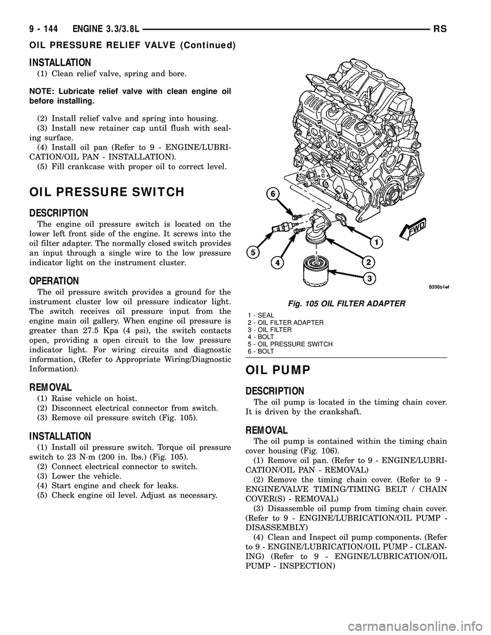
The engine oil pressure switch is located on the
lower left front side of the engine. It screws into the
oil filter adapter. The normally closed switch provides
an input through a single wire to the low pressure
indicator light on the instrument cluster.
OPERATION
The oil pressure switch provides a ground for the
instrument cluster low oil pressure indicator light.
The switch receives oil pressure input from the
engine main oil gallery. When engine oil pressure is
greater than 27.5 Kpa (4 psi), the switch contacts
open, providing a open circuit to the low pressure
indicator light. For wiring circuits and diagnostic
information, (Refer to Appropriate Wiring/Diagnostic
Information).
REMOVAL
(1) Raise vehicle on hoist.
(2) Disconnect electrical connector from switch.
(3) Remove oil pressure switch (Fig. 105).
INSTALLATION
(1) Install oil pressure switch. Torque oil pressure
switch to 23 N´m (200 in. lbs.) (Fig. 105).
(2) Connect electrical connector to switch.
(3) Lower the vehicle.
(4) Start engine and check for leaks.
(5) Check engine oil level. Adjust as necessary.
OIL PUMP
DESCRIPTION
The oil pump is located in the timing chain cover.
It is driven by the crankshaft.
REMOVAL
The oil pump is contained within the timing chain
cover housing (Fig. 106).
(1) Remove oil pan. (Refer to 9 - ENGINE/LUBRI-
CATION/OIL PAN - REMOVAL)
(2) Remove the timing chain cover. (Refer to 9 -
ENGINE/VALVE TIMING/TIMING BELT / CHAIN
COVER(S) - REMOVAL)
(3) Disassemble oil pump from timing chain cover.
(Refer to 9 - ENGINE/LUBRICATION/OIL PUMP -
DISASSEMBLY)
(4) Clean and Inspect oil pump components. (Refer
to 9 - ENGINE/LUBRICATION/OIL PUMP - CLEAN-
ING) (Refer to 9 - ENGINE/LUBRICATION/OIL
PUMP - INSPECTION)
Fig. 105 OIL FILTER ADAPTER
1 - SEAL
2 - OIL FILTER ADAPTER
3 - OIL FILTER
4 - BOLT
5 - OIL PRESSURE SWITCH
6 - BOLT
9 - 144 ENGINE 3.3/3.8LRS
OIL PRESSURE RELIEF VALVE (Continued)
Page 1326 of 2339
INSPECTION
Check manifold for:
²Damage and cracks.
²Mounting surface distortion by using a straight-
edge and thickness gauge.
INSTALLATION - UPPER INTAKE MANIFOLD
(1) If the following components were removed from
manifold, install and tighten to specifications:
CAUTION: The special screws used for the compos-
ite manifold attached components must be installed
slowly using hand tools only. This requirement is to
prevent the melting of material that causes stripped
threads. If threads become stripped, an oversize
repair screw is available. For more information and
procedure (Refer to 9 - ENGINE/MANIFOLDS/IN-
TAKE MANIFOLD - STANDARD PROCEDURE - MAN-
IFOLD STRIPPED THREAD REPAIR).
²MAP sensor - 1.7 N´m (15 in. lbs.)
²Throttle cable bracket - 5.6 N´m (50 in. lbs.)
(2) Remove covering on lower intake manifold and
clean surfaces.
(3) Inspect manifold gasket condition. Gaskets can
be re-used, if not damaged. To replace, remove gasket
from upper manifold (Fig. 118). Position new gasket
in seal channel and press lightly in-place. Repeat
procedure for each gasket position.
(4) Position upper manifold on lower manifold (Fig.
118). Apply MopartLock & Seal Adhesive (Medium
Strength Threadlocker) to each upper intake mani-
fold bolt. Install and tighten bolts to 12 N´m (105 in.
lbs.) following torque sequence in (Fig. 119).
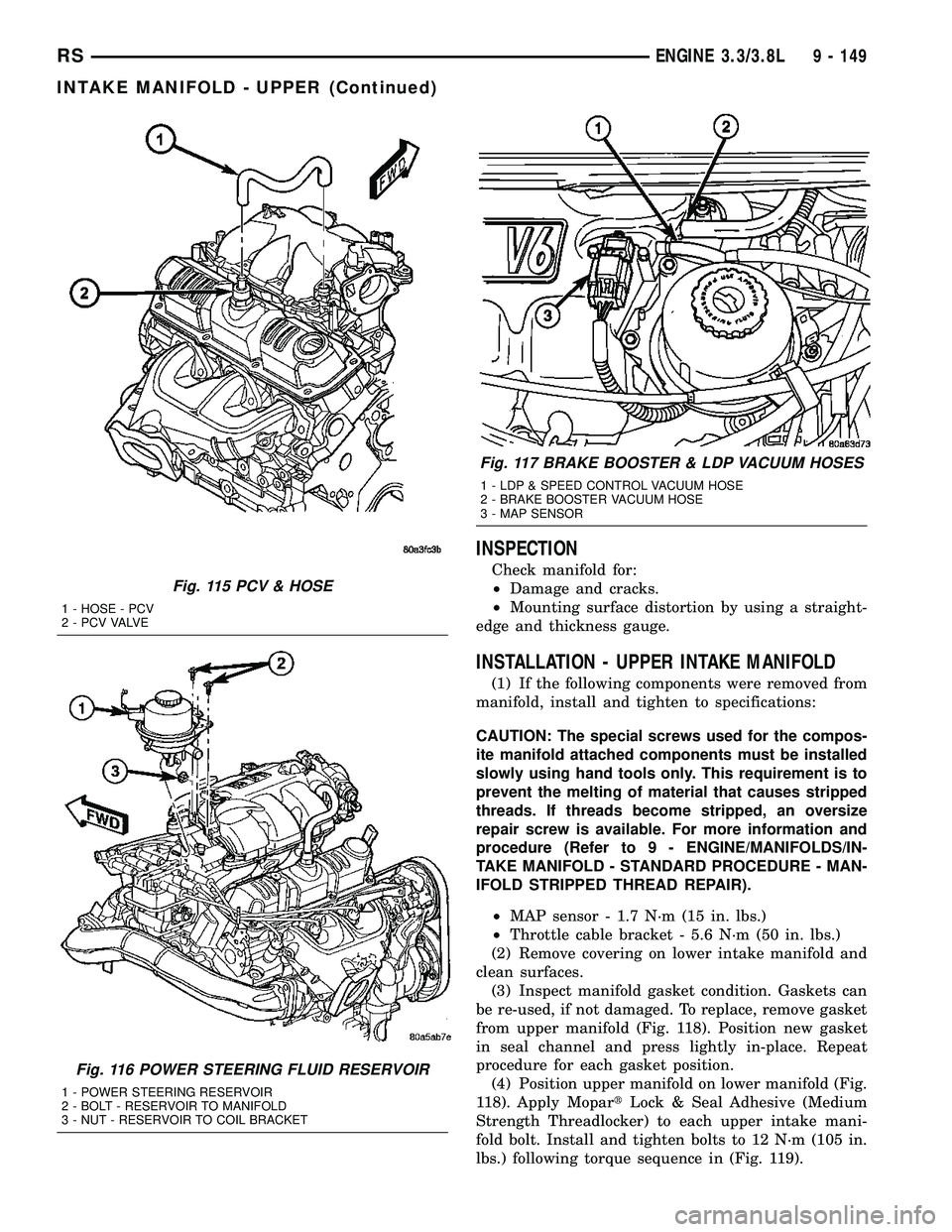
Fig. 115 PCV & HOSE
1 - HOSE - PCV
2 - P C V VA LV E
Fig. 116 POWER STEERING FLUID RESERVOIR
1 - POWER STEERING RESERVOIR
2 - BOLT - RESERVOIR TO MANIFOLD
3 - NUT - RESERVOIR TO COIL BRACKET
Fig. 117 BRAKE BOOSTER & LDP VACUUM HOSES
1 - LDP & SPEED CONTROL VACUUM HOSE
2 - BRAKE BOOSTER VACUUM HOSE
3 - MAP SENSOR
RSENGINE 3.3/3.8L9 - 149
INTAKE MANIFOLD - UPPER (Continued)
Page 1343 of 2339

INSPECTION
WARNING: THE NORMAL OPERATING TEMPERA-
TURE OF THE EXHAUST SYSTEM IS VERY HIGH.
THEREFORE, NEVER ATTEMPT TO SERVICE ANY
PART OF THE EXHAUST SYSTEM UNTIL IT IS
COOLED. SPECIAL CARE SHOULD BE TAKEN
WHEN WORKING NEAR THE CATALYTIC CON-
VERTER. THE TEMPERATURE OF THE CONVERTER
RISES TO A HIGH LEVEL AFTER A SHORT PERIOD
OF ENGINE OPERATION TIME.
Check catalytic converter for a flow restriction.
(Refer to 11 - EXHAUST SYSTEM - DIAGNOSIS
AND TESTING) Exhaust System Restriction Check
for procedure.
Visually inspect the catalytic converter element by
using a borescope or equivalent. Remove oxygen sen-
sor(s) and insert borescope. If borescope is not avail-
able, remove converter and inspect element using a
flashlight. Inspect element for cracked or melted sub-
strate.
NOTE: Before replacing a catalytic converter, deter-
mine the root cause of failure. Most catalytic con-
verter failures are caused by air, fuel or ignition
problems. (Refer to Appropriate Diagnostic Informa-
tion) for test procedures.
INSTALLATION
(1) Position new gasket onto the manifold flange
and install catalytic converter (Fig. 5). Tighten fas-
teners to 37 N´m (325 in. lbs.).
NOTE: Be careful not to twist or kink the oxygen
sensor wires.
(2) Install (if removed) and connect the down-
stream oxygen sensor (Fig. 4).
(3) Install the muffler/resonator assembly. (Refer
to 11 - EXHAUST SYSTEM/MUFFLER - INSTALLA-
TION)
(4) Start the engine and inspect for exhaust leaks.
Repair exhaust leaks as necessary.
(5) Check the exhaust system for contact with the
body panels. Make the necessary adjustments, if
needed.
CROSS-OVER PIPE - 3.3/3.8L
REMOVAL
(1) Disconnect negative cable from battery.
(2) Remove the fasteners attaching the left bank
manifold connection to cross-over pipe (Fig. 6).
(3) Raise vehicle and remove the left front wheel.(4) Access the lower right bank pipe connection
fastener through the left front wheel opening using a
long ratchet extension. Loosen and remove the lower
fastener.
(5) Remove the upper right bank pipe connection
fastener by accessing though the catalytic converter
floor pan tunnel.
(6) Lower the vehicle.
(7) Remove the cross-over pipe (Fig. 6).
(8) Remove gaskets and discard (Fig. 6).
INSTALLATION
(1) Position cross-over pipe to the manifold connec-
tions (Fig. 6).
(2) Position new gasket on left bank (front) pipe
connection and loosely install fasteners (Fig. 6).
(3) Raise the vehicle.
(4) Position new gasket on the right bank pipe con-
nection and install fasteners.
(5) Tighten right bank upper fastener to 41 N´m
(30 ft. lbs.).
(6) Tighten right bank lower fastener to 41 N´m
(30 ft. lbs.) using a long ratchet extension accessing
through the left wheel opening.
(7) Install the left front wheel and lower vehicle.
(8) Tighten the left bank pipe connection fasteners
to 41 N´m (30 ft. lbs.) (Fig. 6).
(9) Start the engine and inspect for exhaust leaks.
Repair exhaust leaks as necessary.
(10) Check the exhaust system for contact with the
body panels. Make the necessary adjustments, if
needed.
Fig. 6 CROSS-OVER PIPE
1 - CROSS-OVER PIPE
2 - BOLT
3 - GASKET
4 - FLAG NUT
11 - 6 EXHAUST SYSTEMRS
CATALYTIC CONVERTER (Continued)
Page 1344 of 2339
HEAT SHIELDS
DESCRIPTION
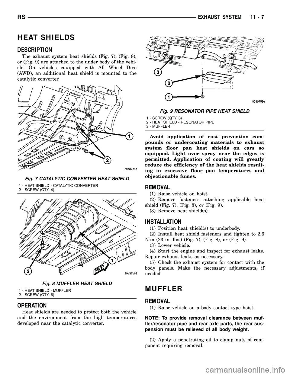
The exhaust system heat shields (Fig. 7), (Fig. 8),
or (Fig. 9) are attached to the under body of the vehi-
cle. On vehicles equipped with All Wheel Dive
(AWD), an additional heat shield is mounted to the
catalytic converter.
OPERATION
Heat shields are needed to protect both the vehicle
and the environment from the high temperatures
developed near the catalytic converter.Avoid application of rust prevention com-
pounds or undercoating materials to exhaust
system floor pan heat shields on cars so
equipped. Light over spray near the edges is
permitted. Application of coating will greatly
reduce the efficiency of the heat shields result-
ing in excessive floor pan temperatures and
objectionable fumes.
REMOVAL
(1) Raise vehicle on hoist.
(2) Remove fasteners attaching applicable heat
shield (Fig. 7), (Fig. 8), or (Fig. 9).
(3) Remove heat shield(s).
INSTALLATION
(1) Position heat shield(s) to underbody.
(2) Install heat shield fasteners and tighten to 2.6
N´m (23 in. lbs.) (Fig. 7), (Fig. 8), or (Fig. 9).
(3) Lower vehicle.
(4) Start the engine and inspect for exhaust leaks.
Repair exhaust leaks as necessary.
(5) Check the exhaust system for contact with the
body panels. Make the necessary adjustments, if
needed.
MUFFLER
REMOVAL
(1) Raise vehicle on a body contact type hoist.
NOTE: To provide removal clearance between muf-
fler/resonator pipe and rear axle parts, the rear sus-
pension must be relieved of all body weight.
(2) Apply a penetrating oil to clamp nuts of com-
ponent requiring removal.
Fig. 7 CATALYTIC CONVERTER HEAT SHIELD
1 - HEAT SHIELD - CATALYTIC CONVERTER
2 - SCREW (QTY. 4)
Fig. 8 MUFFLER HEAT SHIELD
1 - HEAT SHIELD - MUFFLER
2 - SCREW (QTY. 6)
Fig. 9 RESONATOR PIPE HEAT SHIELD
1 - SCREW (QTY. 3)
2 - HEAT SHIELD - RESONATOR PIPE
3 - MUFFLER
RSEXHAUST SYSTEM11-7
Page 1348 of 2339
FRAME & BUMPERS
TABLE OF CONTENTS
page page
BUMPERS
SPECIFICATIONS - TORQUE...............1
FRONT FASCIA
REMOVAL.............................1
INSTALLATION..........................1
FRONT BUMPER REINFORCEMENT
REMOVAL.............................3
INSTALLATION..........................3
REAR FASCIA
REMOVAL.............................4
INSTALLATION..........................4
REAR BUMPER REINFORCEMENT
REMOVAL.............................5
INSTALLATION..........................5
REAR FASCIA - SCUFF PAD
REMOVAL.............................5
INSTALLATION..........................5FRAME
SPECIFICATIONS
SPECIFICATIONS - FRAME DIMENSIONS . . . 6
SPECIFICATIONS - FRAME DIMENSIONS -
FOLD-IN-FLOOR SEATS ONLY...........11
SPECIFICATIONS - TORQUE............14
FRONT CRADLE CROSSMEMBER
DESCRIPTION
DESCRIPTION - FRONT CRADLE
CROSSMEMBER......................14
DESCRIPTION - FRONT CRADLE
CROSSMEMBER THREAD REPAIR........14
REMOVAL.............................15
INSTALLATION.........................16
FRONT CROSSMEMBER MOUNT BUSHINGS
REMOVAL.............................17
INSTALLATION.........................17
BUMPERS
SPECIFICATIONS - TORQUE
DESCRIPTION N´m Ft. Lbs. In. Lbs.
Front bumper reinforcement attaching nut 54 40 Ð
Rear bumper reinforcement attaching nut 27 20 Ð
FRONT FASCIA
REMOVAL
(1) Release hood latch and open hood.
(2) Remove the headlamp assemblies (Refer to 8 -
ELECTRICAL/LAMPS/LIGHTING - EXTERIOR/
HEADLAMP - REMOVAL).
(3) Hoist vehicle and support with safety stands.
(4) Remove the five push pin fasteners attaching
bottom of fascia/air dam to radiator closure panel.
(5) Remove front wheels.
(6) Remove front wheelhouse splash shields fasten-
ers as necessary to gain access to bolts attaching
front fascia to fender. (Refer to 23 - BODY/EXTERI-
OR/ WHEELHOUSE SPLASH SHIELD -
REMOVAL).(7) Remove the two bolts and two nuts attaching
fascia to the front fenders (Fig. 1) and (Fig. 2).
(8) Disconnect fog lamp wire connectors, if neces-
sary.
(9) Lower vehicle.
(10) Remove two bolts attaching the upper grille
support to the headlamp mounting panel at each side
of the grille.
(11) Remove bumper fascia from vehicle.
INSTALLATION
(1) Position front bumper fascia on vehicle (Fig. 1)
and (Fig. 2).
(2) Install the two bolts attaching fascia to head-
lamp mounting panel at each side of grille.
(3) Hoist vehicle and support with safety stands.
RSFRAME & BUMPERS13-1
Page 1349 of 2339
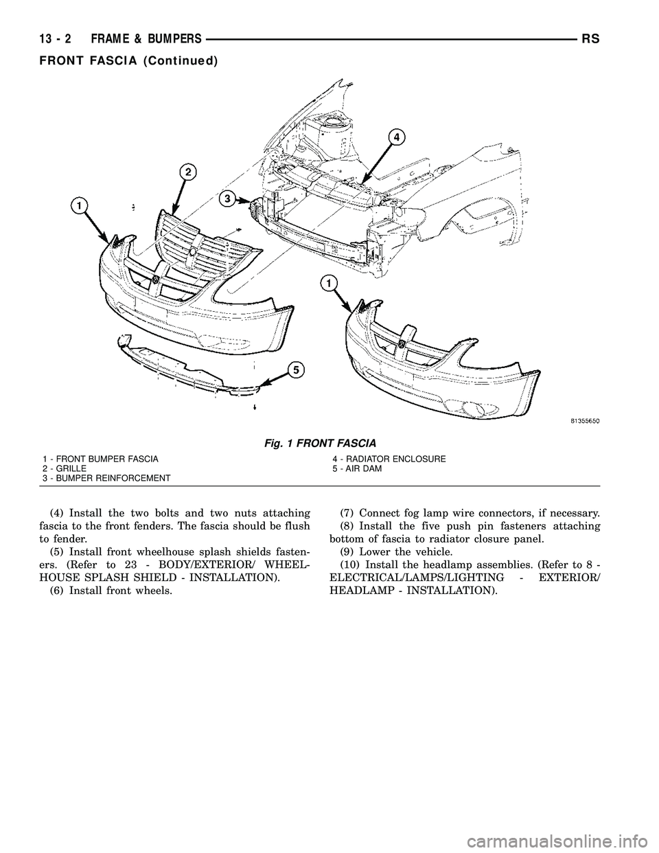
(4) Install the two bolts and two nuts attaching
fascia to the front fenders. The fascia should be flush
to fender.
(5) Install front wheelhouse splash shields fasten-
ers. (Refer to 23 - BODY/EXTERIOR/ WHEEL-
HOUSE SPLASH SHIELD - INSTALLATION).
(6) Install front wheels.(7) Connect fog lamp wire connectors, if necessary.
(8) Install the five push pin fasteners attaching
bottom of fascia to radiator closure panel.
(9) Lower the vehicle.
(10) Install the headlamp assemblies. (Refer to 8 -
ELECTRICAL/LAMPS/LIGHTING - EXTERIOR/
HEADLAMP - INSTALLATION).
Fig. 1 FRONT FASCIA
1 - FRONT BUMPER FASCIA
2 - GRILLE
3 - BUMPER REINFORCEMENT4 - RADIATOR ENCLOSURE
5 - AIR DAM
13 - 2 FRAME & BUMPERSRS
FRONT FASCIA (Continued)
Page 1368 of 2339
(6) Open fuel fill door and remove screws mount-
ing fuel filler tube assembly to body. Do not discon-
nect rubber fuel fill or vent hoses from tank at this
time.
(7) Place a transmission jack under center of fuel
tank. Apply a slight amount of pressure to fuel tank
with transmission jack.
(8) Remove fuel tank mounting straps.
(9)Lower the tank just enough so that the
filler tube fitting is the highest point of the fuel
tank.
(10) Remove filler tube from fuel tank. Tank will
be drained through this fitting.
NOTE: WRAP SHOP TOWELS AROUND HOSES TO
CATCH ANY GASOLINE SPILLAGE.
(11) Drain fuel tank into holding tank or a prop-
erly labeledGasolinesafety container.
WARNING: GASOLINE OR GASOLINE VAPORS ARE
HIGHLY FLAMMABLE. A FIRE COULD OCCUR IF AN
IGNITION SOURCE IS PRESENT. NEVER DRAIN OR
STORE GASOLINE OR DIESEL FUEL IN AN OPEN
CONTAINER, DUE TO THE POSSIBILITY OF FIRE
OR EXPLOSION. THIS MAY RESULT IN PERSONAL
INJURY OR DEATH.
(12) If fuel pump module removal is necessary,
refer to Fuel Pump Module Removal/Installation in
this section.
STANDARD PROCEDURE - FUEL PRESSURE
GAUGE
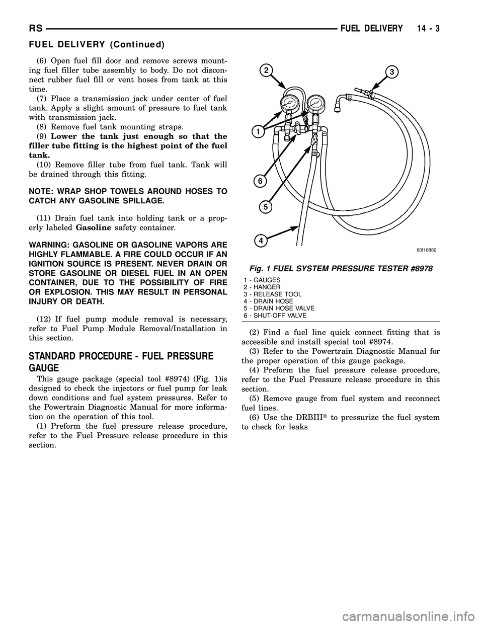
This gauge package (special tool #8974) (Fig. 1)is
designed to check the injectors or fuel pump for leak
down conditions and fuel system pressures. Refer to
the Powertrain Diagnostic Manual for more informa-
tion on the operation of this tool.
(1) Preform the fuel pressure release procedure,
refer to the Fuel Pressure release procedure in this
section.(2) Find a fuel line quick connect fitting that is
accessible and install special tool #8974.
(3) Refer to the Powertrain Diagnostic Manual for
the proper operation of this gauge package.
(4) Preform the fuel pressure release procedure,
refer to the Fuel Pressure release procedure in this
section.
(5) Remove gauge from fuel system and reconnect
fuel lines.
(6) Use the DRBIIItto pressurize the fuel system
to check for leaks
Fig. 1 FUEL SYSTEM PRESSURE TESTER #8978
1 - GAUGES
2 - HANGER
3 - RELEASE TOOL
4 - DRAIN HOSE
5 - DRAIN HOSE VALVE
6 - SHUT-OFF VALVE
RSFUEL DELIVERY14-3
FUEL DELIVERY (Continued)
Page 1371 of 2339
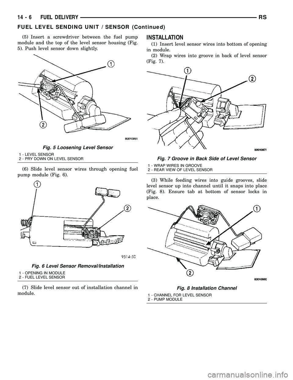
(5) Insert a screwdriver between the fuel pump
module and the top of the level sensor housing (Fig.
5). Push level sensor down slightly.
(6) Slide level sensor wires through opening fuel
pump module (Fig. 6).
(7) Slide level sensor out of installation channel in
module.INSTALLATION
(1) Insert level sensor wires into bottom of opening
in module.
(2) Wrap wires into groove in back of level sensor
(Fig. 7).
(3) While feeding wires into guide grooves, slide
level sensor up into channel until it snaps into place
(Fig. 8). Ensure tab at bottom of sensor locks in
place.
Fig. 5 Loosening Level Sensor
1 - LEVEL SENSOR
2 - PRY DOWN ON LEVEL SENSOR
Fig. 6 Level Sensor Removal/Installation
1 - OPENING IN MODULE
2 - FUEL LEVEL SENSOR
Fig. 7 Groove in Back Side of Level Sensor
1 - WRAP WIRES IN GROOVE
2 - REAR VIEW OF LEVEL SENSOR
Fig. 8 Installation Channel
1 - CHANNEL FOR LEVEL SENSOR
2 - PUMP MODULE
14 - 6 FUEL DELIVERYRS
FUEL LEVEL SENDING UNIT / SENSOR (Continued)