2005 CHRYSLER CARAVAN clock
[x] Cancel search: clockPage 1759 of 2339
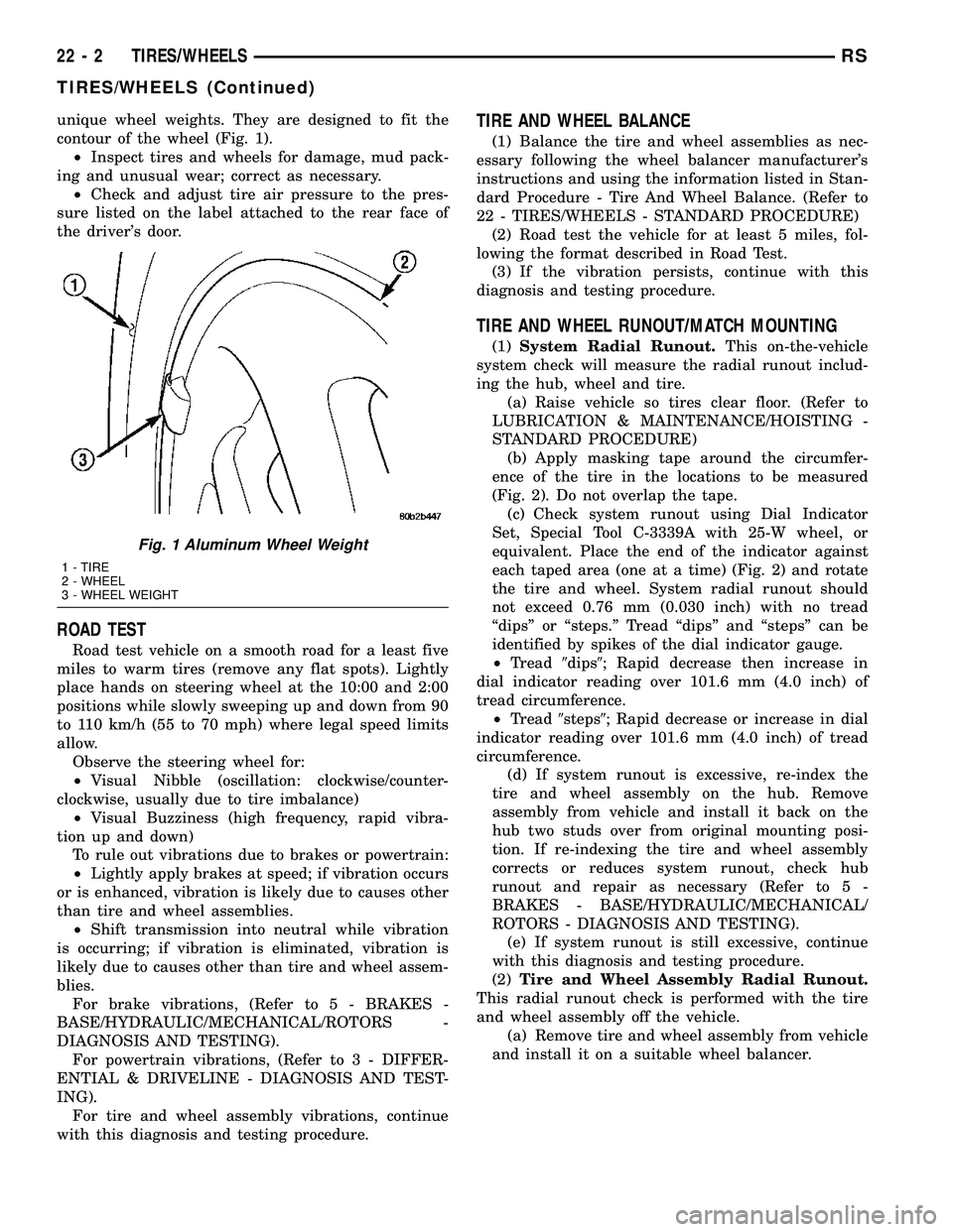
unique wheel weights. They are designed to fit the
contour of the wheel (Fig. 1).
²Inspect tires and wheels for damage, mud pack-
ing and unusual wear; correct as necessary.
²Check and adjust tire air pressure to the pres-
sure listed on the label attached to the rear face of
the driver's door.
ROAD TEST
Road test vehicle on a smooth road for a least five
miles to warm tires (remove any flat spots). Lightly
place hands on steering wheel at the 10:00 and 2:00
positions while slowly sweeping up and down from 90
to 110 km/h (55 to 70 mph) where legal speed limits
allow.
Observe the steering wheel for:
²Visual Nibble (oscillation: clockwise/counter-
clockwise, usually due to tire imbalance)
²Visual Buzziness (high frequency, rapid vibra-
tion up and down)
To rule out vibrations due to brakes or powertrain:
²Lightly apply brakes at speed; if vibration occurs
or is enhanced, vibration is likely due to causes other
than tire and wheel assemblies.
²Shift transmission into neutral while vibration
is occurring; if vibration is eliminated, vibration is
likely due to causes other than tire and wheel assem-
blies.
For brake vibrations, (Refer to 5 - BRAKES -
BASE/HYDRAULIC/MECHANICAL/ROTORS -
DIAGNOSIS AND TESTING).
For powertrain vibrations, (Refer to 3 - DIFFER-
ENTIAL & DRIVELINE - DIAGNOSIS AND TEST-
ING).
For tire and wheel assembly vibrations, continue
with this diagnosis and testing procedure.
TIRE AND WHEEL BALANCE
(1) Balance the tire and wheel assemblies as nec-
essary following the wheel balancer manufacturer's
instructions and using the information listed in Stan-
dard Procedure - Tire And Wheel Balance. (Refer to
22 - TIRES/WHEELS - STANDARD PROCEDURE)
(2) Road test the vehicle for at least 5 miles, fol-
lowing the format described in Road Test.
(3) If the vibration persists, continue with this
diagnosis and testing procedure.
TIRE AND WHEEL RUNOUT/MATCH MOUNTING
(1)System Radial Runout.This on-the-vehicle
system check will measure the radial runout includ-
ing the hub, wheel and tire.
(a) Raise vehicle so tires clear floor. (Refer to
LUBRICATION & MAINTENANCE/HOISTING -
STANDARD PROCEDURE)
(b) Apply masking tape around the circumfer-
ence of the tire in the locations to be measured
(Fig. 2). Do not overlap the tape.
(c) Check system runout using Dial Indicator
Set, Special Tool C-3339A with 25-W wheel, or
equivalent. Place the end of the indicator against
each taped area (one at a time) (Fig. 2) and rotate
the tire and wheel. System radial runout should
not exceed 0.76 mm (0.030 inch) with no tread
ªdipsº or ªsteps.º Tread ªdipsº and ªstepsº can be
identified by spikes of the dial indicator gauge.
²Tread9dips9; Rapid decrease then increase in
dial indicator reading over 101.6 mm (4.0 inch) of
tread circumference.
²Tread9steps9; Rapid decrease or increase in dial
indicator reading over 101.6 mm (4.0 inch) of tread
circumference.
(d) If system runout is excessive, re-index the
tire and wheel assembly on the hub. Remove
assembly from vehicle and install it back on the
hub two studs over from original mounting posi-
tion. If re-indexing the tire and wheel assembly
corrects or reduces system runout, check hub
runout and repair as necessary (Refer to 5 -
BRAKES - BASE/HYDRAULIC/MECHANICAL/
ROTORS - DIAGNOSIS AND TESTING).
(e) If system runout is still excessive, continue
with this diagnosis and testing procedure.
(2)Tire and Wheel Assembly Radial Runout.
This radial runout check is performed with the tire
and wheel assembly off the vehicle.
(a) Remove tire and wheel assembly from vehicle
and install it on a suitable wheel balancer.
Fig. 1 Aluminum Wheel Weight
1 - TIRE
2 - WHEEL
3 - WHEEL WEIGHT
22 - 2 TIRES/WHEELSRS
TIRES/WHEELS (Continued)
Page 1765 of 2339
REMOVAL
REMOVAL - TIRE AND WHEEL ASSEMBLY
(ALUMINUM WHEEL)
(1) Raise the vehicle so the tire and wheel assem-
bly clears ground level.
(2) Remove the 5 wheel mounting nuts from the
studs.
(3) Remove the tire and wheel from the hub.
REMOVAL - TIRE AND WHEEL ASSEMBLY
(STEEL WHEEL)
(1) Raise the vehicle so the tire and wheel assem-
bly clears ground level.
(2) Noting the location of the valve stem in rela-
tionship to the wheel mounting nuts, remove the
three wheel mounting nuts securing the wheel cover
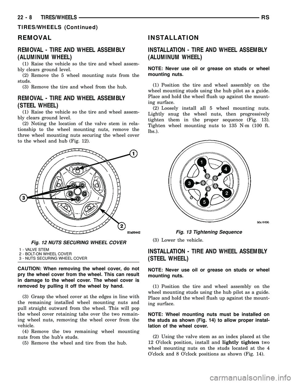
to the wheel and hub (Fig. 12).
CAUTION: When removing the wheel cover, do not
pry the wheel cover from the wheel. This can result
in damage to the wheel cover. The wheel cover is
removed by pulling it off the wheel by hand.
(3) Grasp the wheel cover at the edges in line with
the remaining installed wheel mounting nuts and
pull straight outward from the wheel. This will pop
the wheel cover retaining tabs over the two remain-
ing wheel nuts, removing the wheel cover from the
vehicle.
(4) Remove the two remaining wheel mounting
nuts from the hub's studs.
(5) Remove the wheel and tire from the hub.
INSTALLATION
INSTALLATION - TIRE AND WHEEL ASSEMBLY
(ALUMINUM WHEEL)
NOTE: Never use oil or grease on studs or wheel
mounting nuts.
(1) Position the tire and wheel assembly on the
wheel mounting studs using the hub pilot as a guide.
Place and hold the wheel flush up against the mount-
ing surface.
(2) Loosely install all 5 wheel mounting nuts.
Lightly snug the wheel nuts, then progressively
tighten them in the proper sequence (Fig. 13).
Tighten wheel mounting nuts to 135 N´m (100 ft.
lbs.).
(3) Lower the vehicle.
INSTALLATION - TIRE AND WHEEL ASSEMBLY
(STEEL WHEEL)
NOTE: Never use oil or grease on studs or wheel
mounting nuts.
(1) Position the tire and wheel assembly on the
wheel mounting studs using the hub pilot as a guide.
Place and hold the wheel flush up against the mount-
ing surface.
NOTE: Wheel mounting nuts must be installed on
the studs as shown (Fig. 14) to allow proper instal-
lation of the wheel cover.
(2) Using the valve stem as an index placed at the
12 O'clock position, install andlightly tightentwo
wheel mounting nuts on the studs located at the 4
O'clock and 8 O'clock positions as shown (Fig. 14).
Fig. 12 NUTS SECURING WHEEL COVER
1 - VALVE STEM
2 - BOLT-ON WHEEL COVER
3 - NUTS SECURING WHEEL COVER
Fig. 13 Tightening Sequence
22 - 8 TIRES/WHEELSRS
TIRES/WHEELS (Continued)
Page 1769 of 2339
CAUTION: Over-torquing the sensor nut by as little
as 12 N´m (106 in. lbs.) may result in sensor sepa-
ration from the valve stem. Under this condition,
the sensor may still function, however, the condi-
tion should be corrected immediately.
(4) Mount tire on wheel following tire changer
manufacturers instructions, paying special attention
to the following to avoid damaging tire pressure sen-
sor:
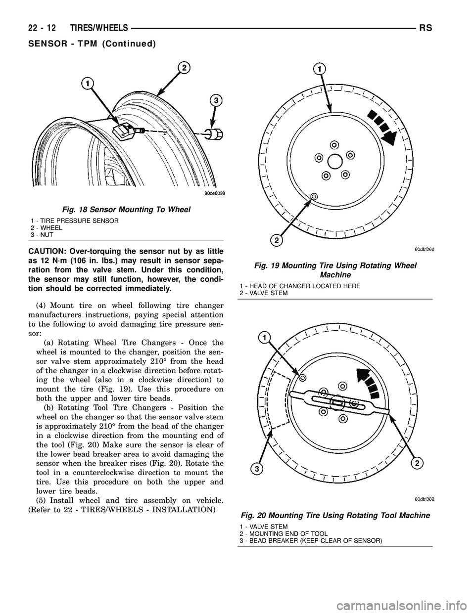
(a) Rotating Wheel Tire Changers - Once the
wheel is mounted to the changer, position the sen-
sor valve stem approximately 210É from the head
of the changer in a clockwise direction before rotat-
ing the wheel (also in a clockwise direction) to
mount the tire (Fig. 19). Use this procedure on
both the upper and lower tire beads.
(b) Rotating Tool Tire Changers - Position the
wheel on the changer so that the sensor valve stem
is approximately 210É from the head of the changer
in a clockwise direction from the mounting end of
the tool (Fig. 20) Make sure the sensor is clear of
the lower bead breaker area to avoid damaging the
sensor when the breaker rises (Fig. 20). Rotate the
tool in a counterclockwise direction to mount the
tire. Use this procedure on both the upper and
lower tire beads.
(5) Install wheel and tire assembly on vehicle.
(Refer to 22 - TIRES/WHEELS - INSTALLATION)
Fig. 18 Sensor Mounting To Wheel
1 - TIRE PRESSURE SENSOR
2 - WHEEL
3 - NUT
Fig. 19 Mounting Tire Using Rotating Wheel
Machine
1 - HEAD OF CHANGER LOCATED HERE
2 - VALVE STEM
Fig. 20 Mounting Tire Using Rotating Tool Machine
1 - VALVE STEM
2 - MOUNTING END OF TOOL
3 - BEAD BREAKER (KEEP CLEAR OF SENSOR)
22 - 12 TIRES/WHEELSRS
SENSOR - TPM (Continued)
Page 1810 of 2339
(4) Check door for height using character lines as
a reference. Also check roof contour as a controlling
factor.
Using the procedures noted below, adjust the side
door in the order the individual steps are called out.
DOOR FLUSHNESS ADJUSTMENT
(1) Check sliding door flushness at the C-pillar
striker.
(2) If the sliding door is under or over flush,
remove striker assembly and move thread plate over
keeping one bolt in plate so it will not fall between
inner and outer panels.
(3) Adjust the C-pillar striker in or out until the
door is flush. Then, the on size hole can be elongated
in the direction required. This can be done by grind-
ing or filing the sheet metal and then painting raw
edge to prevent rusting.
(4) Check upper B-pillar flushness to A-pillar
cover.
(5) The sliding door upper hinge can only be
moved outboard by addinga1mmshim behind the
hinge mounting area once the two attachment bolts
are removed and reinstalled.
(6) Check flushness at upper C-pillar.
(7) If upper C-pillar flushness is out of specifica-
tion use a heavy rubber mallet on the door assembly
until door is in specifications.
DOOR GAP ADJUSTMENT - UP/DOWN
(1) Check height of sliding door at the B-pillar and
C-pillar to determine which area is contributing the
greatest to the incorrect gaps.
(2) Visually inspect the sliding door for fitting low
at the top of the door by checking the alignment of
the top contour of the door to the quarter panel.
(3) If the sliding door is high at the C-pillar.
(a) Open the door to mid-point of travel.
(b) Mark outline of center hinge on sliding door
to assist in making adjustments.
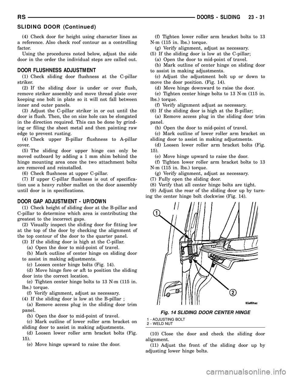
(c) Loosen center hinge bolts (Fig. 14).
(d) Move hinge fore or aft to position the sliding
door into the correct location.
(e) Tighten center hinge bolts to 13 N´m (115 in.
lbs.) torque.
(f) Verify alignment, adjust as necessary.
(4) If the sliding door is low at the B-pillar ;
(a) Remove access plug in the sliding door trim
panel.
(b) Open the door to mid-point of travel.
(c) Mark outline of lower roller arm bracket on
sliding door to assist in making adjustments.
(d) Loosen lower roller arm bracket bolts (Fig.
15).
(e) Move hinge upward to raise the door.(f) Tighten lower roller arm bracket bolts to 13
N´m (115 in. lbs.) torque.
(g) Verify alignment, adjust as necessary.
(5) If the sliding door is low at the C-pillar;
(a) Open the door to mid-point of travel.
(b) Mark outline of center hinge on sliding door
to assist in making adjustments.
(c) Adjust the adjustment bolt up or down to
move the door position. (Fig. 14).
(d) Move hinge downward to raise the door.
(e) Tighten center hinge bolts to 13 N´m (115 in.
lbs.) torque.
(f) Verify alignment adjust as necessary.
(6) If the sliding door is high at the B-pillar;
(a) Remove access plug in the sliding door trim
panel.
(b) Open the door to mid-point of travel.
(c) Mark outline of lower roller arm bracket on
sliding door to assist in making adjustments.
(d) Loosen lower roller arm bracket bolts (Fig.
15).
(e) Move hinge upward to raise the door.
(f) Tighten lower roller arm bracket bolts to 13
N´m (115 in. lbs.) torque.
(g) Verify alignment, adjust as necessary.
(7) Fully open the sliding door.
(8) Verify that all center hinge bolts are tight.
(9) Adjust the rear of the sliding door up by turn-
ing the center hinge bolt clockwise (Fig. 14).
(10) Close the door and check the sliding door
alignment.
(11) Adjust the front of the sliding door up by
adjusting lower hinge bolts.
Fig. 14 SLIDING DOOR CENTER HINGE
1 - ADJUSTING BOLT
2 - WELD NUT
RSDOORS - SLIDING23-31
SLIDING DOOR (Continued)
Page 1848 of 2339
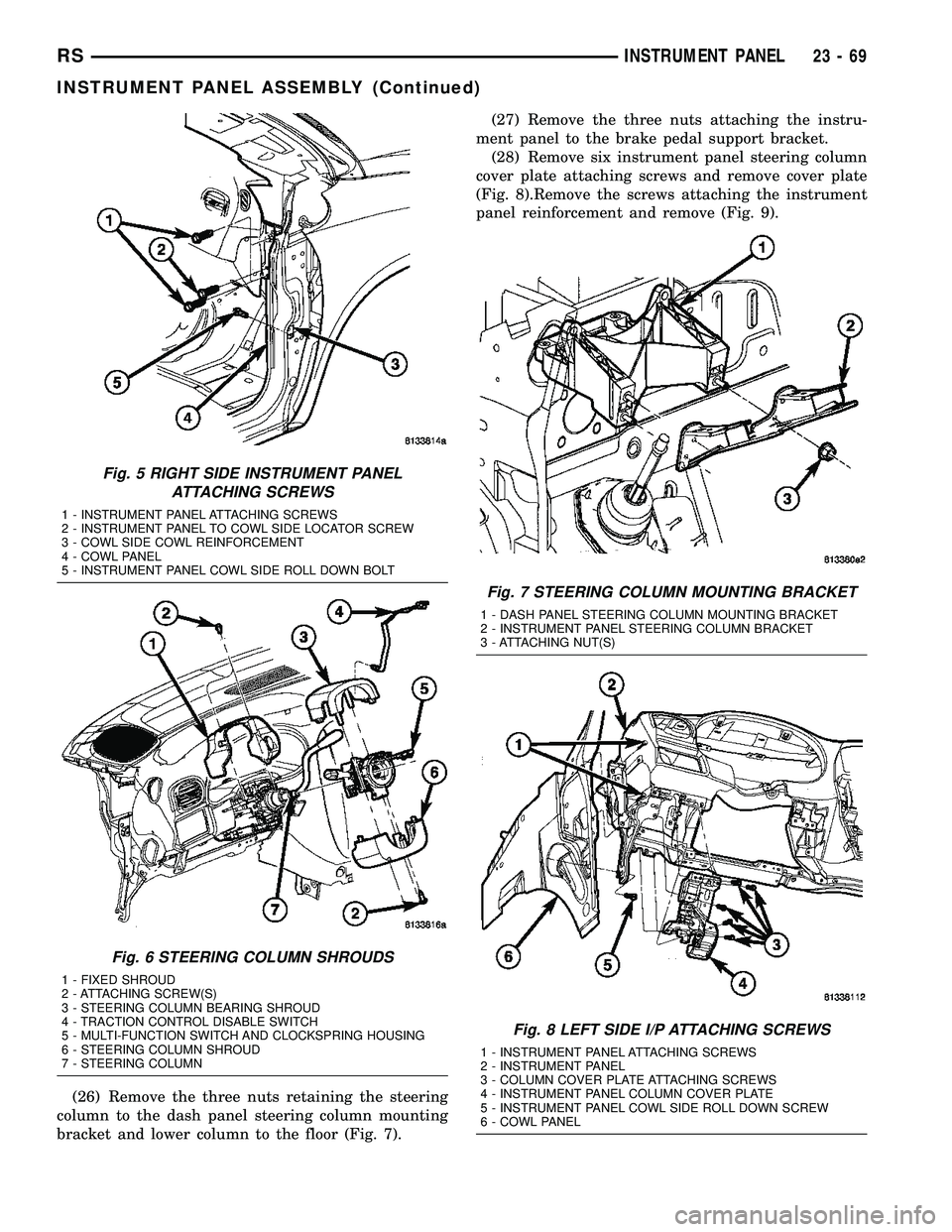
(26) Remove the three nuts retaining the steering
column to the dash panel steering column mounting
bracket and lower column to the floor (Fig. 7).(27) Remove the three nuts attaching the instru-
ment panel to the brake pedal support bracket.
(28) Remove six instrument panel steering column
cover plate attaching screws and remove cover plate
(Fig. 8).Remove the screws attaching the instrument
panel reinforcement and remove (Fig. 9).
Fig. 5 RIGHT SIDE INSTRUMENT PANEL
ATTACHING SCREWS
1 - INSTRUMENT PANEL ATTACHING SCREWS
2 - INSTRUMENT PANEL TO COWL SIDE LOCATOR SCREW
3 - COWL SIDE COWL REINFORCEMENT
4 - COWL PANEL
5 - INSTRUMENT PANEL COWL SIDE ROLL DOWN BOLT
Fig. 6 STEERING COLUMN SHROUDS
1 - FIXED SHROUD
2 - ATTACHING SCREW(S)
3 - STEERING COLUMN BEARING SHROUD
4 - TRACTION CONTROL DISABLE SWITCH
5 - MULTI-FUNCTION SWITCH AND CLOCKSPRING HOUSING
6 - STEERING COLUMN SHROUD
7 - STEERING COLUMN
Fig. 7 STEERING COLUMN MOUNTING BRACKET
1 - DASH PANEL STEERING COLUMN MOUNTING BRACKET
2 - INSTRUMENT PANEL STEERING COLUMN BRACKET
3 - ATTACHING NUT(S)
Fig. 8 LEFT SIDE I/P ATTACHING SCREWS
1 - INSTRUMENT PANEL ATTACHING SCREWS
2 - INSTRUMENT PANEL
3 - COLUMN COVER PLATE ATTACHING SCREWS
4 - INSTRUMENT PANEL COLUMN COVER PLATE
5 - INSTRUMENT PANEL COWL SIDE ROLL DOWN SCREW
6 - COWL PANEL
RSINSTRUMENT PANEL23-69
INSTRUMENT PANEL ASSEMBLY (Continued)
Page 1929 of 2339
UNDER SEAT STORAGE BIN
GUIDE
REMOVAL
(1) Remove under seat storage bin. (Refer to 23 -
BODY/SEATS/UNDER SEAT STORAGE BIN -
REMOVAL)
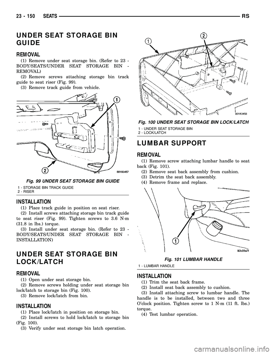
(2) Remove screws attaching storage bin track
guide to seat riser (Fig. 99).
(3) Remove track guide from vehicle.
INSTALLATION
(1) Place track guide in position on seat riser.
(2) Install screws attaching storage bin track guide
to seat riser (Fig. 99). Tighten screws to 3.6 N´m
(31.8 in lbs.) torque.
(3) Install under seat storage bin. (Refer to 23 -
BODY/SEATS/UNDER SEAT STORAGE BIN -
INSTALLATION)
UNDER SEAT STORAGE BIN
LOCK/LATCH
REMOVAL
(1) Open under seat storage bin.
(2) Remove screws holding under seat storage bin
lock/latch to storage bin (Fig. 100).
(3) Remove lock/latch from bin.
INSTALLATION
(1) Place lock/latch in position on storage bin.
(2) Install screws to hold lock/latch to storage bin
(Fig. 100).
(3) Verify under seat storage bin latch operation.
LUMBAR SUPPORT
REMOVAL
(1) Remove screw attaching lumbar handle to seat
back (Fig. 101).
(2) Remove seat back assembly from cushion.
(3) Detrim the seat back assembly.
(4) Remove frame and replace.
INSTALLATION
(1) Trim the seat back frame.
(2) Install seat back assembly to cushion.
(3) Install attaching screw to lumbar handle. The
handle is to be installed, between two and three
O'clock position. Tighten screw to 1 N´m (11 ft. lbs.)
torque.
(4) Test lumbar operation.
Fig. 99 UNDER SEAT STORAGE BIN GUIDE
1 - STORAGE BIN TRACK GUIDE
2 - RISER
Fig. 100 UNDER SEAT STORAGE BIN LOCK/LATCH
1 - UNDER SEAT STORAGE BIN
2 - LOCK/LATCH
Fig. 101 LUMBAR HANDLE
1 - LUMBAR HANDLE
23 - 150 SEATSRS
Page 2185 of 2339
INSTALLATION
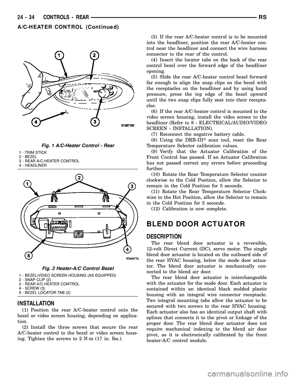
(1) Position the rear A/C-heater control onto the
bezel or video screen housing, depending on applica-
tion.
(2) Install the three screws that secure the rear
A/C-heater control to the bezel or video screen hous-
ing. Tighten the screws to 2 N´m (17 in. lbs.).(3) If the rear A/C-heater control is to be mounted
into the headliner, position the rear A/C-heater con-
trol near the headliner and connect the wire harness
connector to the rear of the control.
(4) Insert the locator tabs on the back of the rear
control bezel over the forward edge of the headliner
opening.
(5) Slide the rear A/C-heater control bezel forward
far enough to align the snap clips on the bezel with
the receptacles on the headliner and by using hand
pressure, press the top edge of the bezel upward
until the two snap clips fully seat into their recepta-
cles.
(6) If the rear A/C-heater control is mounted to the
video screen housing, install the video screen to the
headliner (Refer to 8 - ELECTRICAL/AUDIO/VIDEO
SCREEN - INSTALLATION).
(7) Reconnect the negative battery cable.
(8) Using the DRB-IIItscan tool, reset the Rear
Temperature Selector calibration values.
(9) Verify that the Actuator Calibration of the
Front Control has passed. If an Actuator Calibration
has not passed correct any errors before proceeding
further.
(10) Rotate the Rear Temperature Selector counter
clockwise to the Cold Position, allow the Selector to
remain in the Cold Position for 5 seconds.
(11) Rotate the Rear Temperature Selector Clock-
wise to the Hot Position, allow the Selector to remain
in the Cold Position for 5 seconds.
(12) Calibration is now complete.
BLEND DOOR ACTUATOR
DESCRIPTION
The rear blend door actuator is a reversible,
12-volt Direct Current (DC), servo motor. The single
blend door actuator is located on the outboard side of
the rear HVAC housing, below the mode door actua-
tor. The blend door actuator is mechanically con-
nected to the blend air door.
The rear blend door actuator is interchangeable
with the actuator for the mode door. Each actuator is
contained within an identical black molded plastic
housing with an integral wire connector receptacle.
Two integral mounting tabs allow the actuator to be
secured with two screws to the rear HVAC housing.
Each actuator also has an identical output shaft with
splines that connects it to the pivot or linkage of the
proper door. The rear blend door actuator does not
require mechanical indexing to the blend air door
pivot, as it is electronically calibrated by the front
heater-A/C control module.
Fig. 1 A/C-Heater Control - Rear
1 - TRIM STICK
2 - BEZEL
3 - REAR A/C-HEATER CONTROL
4 - HEADLINER
Fig. 2 Heater-A/C Control Bezel
1 - BEZEL/VIDEO SCREEN HOUSING (AS EQUIPPED)
2 - SNAP CLIP (2)
3 - REAR A/C-HEATER CONTROL
4 - SCREW (3)
5 - BEZEL LOCATOR TAB (2)
24 - 34 CONTROLS - REARRS
A/C-HEATER CONTROL (Continued)
Page 2220 of 2339
(4) Raise the liquid line (discharge) pressure to
about 1793 kPa (260 psi) by placing a piece of card-
board over part of the front side of the condenser. To
place the cardboard properly, remove the upper radi-
ator sight shield from the front fascia. Cover only
enough of the condenser to raise and maintain the
liquid line pressure at the specified level.
(5) Observe the liquid line (discharge) pressure
and liquid line temperature. Using the Charge Deter-
mination Chart (Fig. 1), determine whether the
refrigerant system is operating within the Proper
Charge Range.
(a) If the refrigerant system is operating in the
Undercharged area of the chart, add 0.057 kilo-
gram (0.125 pound or 2 ounces) of refrigerant to
the system.
(b) If the refrigerant system is operating in the
Overcharged area of the chart, reclaim 0.057 kilo-
gram (0.125 pound or 2 ounces) of refrigerant from
the system.
(6) Recheck the system charge level following each
refrigerant adjustment. Continue this process until
the system readings are in the Proper Charge Range
area on the Charge Determination Chart.
STANDARD PROCEDURE
HANDLING TUBING AND FITTINGS
CAUTION: The system must be completely empty
before opening any fitting or connection in the
refrigeration system. Open fittings with caution
even after the system has been emptied. If any
pressure is noticed as a fitting is loosened,
retighten fitting and evacuate the system again.
A good rule for the flexible hose lines is to keep the
radius of all bends at least 10 times the diameter of
the hose. Sharper bends will reduce the flow of
refrigerant. The flexible hose lines should be routed
so they are at least 3 inches (80 mm) from the
exhaust manifold. Inspect all flexible hose lines to
make sure they are in good condition and properly
routed.
The use of correct wrenches when making connec-
tions is very important. Improper wrenches or
improper use of wrenches can damage the fittings.
The internal parts of the A/C system will remain sta-
ble as long as moisture-free refrigerant and refrig-
erant oil is used. Abnormal amounts of dirt,
moisture or air can upset the chemical stability.
This may cause operational troubles or even seri-
ous damage if present in more than very small
quantities. Before disconnecting a component,
clean the outside of the fittings thoroughly to pre-
vent contamination from entering the refrigerant
system.When opening a refrigeration system, have every-
thing you will need to repair the system ready. This
will minimize the amount of time the system must
be opened. Cap or plug all lines and fittings as
soon as they are opened. This will help prevent the
entrance of dirt and moisture. All new lines and
components should be capped or sealed until they
are ready to be used. Before connecting a compo-
nent, clean the outside of the fittings thoroughly to
prevent contamination from entering the refrigerant
system.
All tools, including the refrigerant dispensing mani-
fold, the manifold gauge set, and test hoses should
be kept clean and dry.
Kinks in the refrigerant tubing or sharp bends in
the refrigerant hose lines will greatly reduce the
capacity of the entire system. High pressures are pro-
duced in the system when it is operating. Extreme
care must be exercised to make sure that all connec-
tions are pressure tight. Dirt and moisture can enter
the system when it is opened for repair or replace-
ment of lines or components. The refrigerant oil will
absorb moisture readily out of the air. This moisture
will convert into acids within a closed system.
REFRIGERANT SYSTEM SERVICE EQUIPMENT
WARNING: EYE PROTECTION MUST BE WORN
WHEN SERVICING AN AIR CONDITIONING REFRIG-
ERANT SYSTEM. TURN OFF (ROTATE CLOCKWISE)
ALL VALVES ON THE EQUIPMENT BEING USED
BEFORE CONNECTING TO, OR DISCONNECTING
FROM THE REFRIGERANT SYSTEM. FAILURE TO
OBSERVE THESE WARNINGS MAY RESULT IN PER-
SONAL INJURY.
WARNING: REVIEW THE WARNINGS AND CAU-
TIONS IN THE FRONT OF THIS SECTION BEFORE
PERFORMING THE FOLLOWING OPERATION (Refer
to 24 - HEATING & AIR CONDITIONING/PLUMBING -
WARNING) and (Refer to 24 - HEATING & AIR CON-
DITIONING/PLUMBING - CAUTION).
RECOVERY/RECYCLING STATION
When servicing the air conditioning system, a
R-134a refrigerant recovery/recycling/charging sta-
tion that meets SEA Standard J2210 must be used
(Fig. 2). Contact an automotive service equipment
supplier for refrigerant recovery/recycling/charging
equipment. See the operating instructions supplied
by the equipment manufacturer for proper care and
use of this equipment.
RSPLUMBING - FRONT24-69
PLUMBING - FRONT (Continued)