Page 1589 of 2339

OPERATION
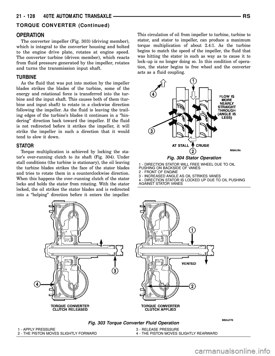
The converter impeller (Fig. 303) (driving member),
which is integral to the converter housing and bolted
to the engine drive plate, rotates at engine speed.
The converter turbine (driven member), which reacts
from fluid pressure generated by the impeller, rotates
and turns the transmission input shaft.
TURBINE
As the fluid that was put into motion by the impeller
blades strikes the blades of the turbine, some of the
energy and rotational force is transferred into the tur-
bine and the input shaft. This causes both of them (tur-
bine and input shaft) to rotate in a clockwise direction
following the impeller. As the fluid is leaving the trail-
ing edges of the turbine's blades it continues in a ªhin-
deringº direction back toward the impeller. If the fluid
is not redirected before it strikes the impeller, it will
strike the impeller in such a direction that it would
tend to slow it down.
STATOR
Torque multiplication is achieved by locking the sta-
tor's over-running clutch to its shaft (Fig. 304). Under
stall conditions (the turbine is stationary), the oil leaving
the turbine blades strikes the face of the stator blades
and tries to rotate them in a counterclockwise direction.
When this happens the over±running clutch of the stator
locks and holds the stator from rotating. With the stator
locked, the oil strikes the stator blades and is redirected
into a ªhelpingº direction before it enters the impeller.This circulation of oil from impeller to turbine, turbine to
stator, and stator to impeller, can produce a maximum
torque multiplication of about 2.4:1. As the turbine
begins to match the speed of the impeller, the fluid that
was hitting the stator in such as way as to cause it to
lock±up is no longer doing so. In this condition of opera-
tion, the stator begins to free wheel and the converter
acts as a fluid coupling.
Fig. 303 Torque Converter Fluid Operation
1 - APPLY PRESSURE 3 - RELEASE PRESSURE
2 - THE PISTON MOVES SLIGHTLY FORWARD 4 - THE PISTON MOVES SLIGHTLY REARWARD
Fig. 304 Stator Operation
1 - DIRECTION STATOR WILL FREE WHEEL DUE TO OIL
PUSHING ON BACKSIDE OF VANES
2 - FRONT OF ENGINE
3 - INCREASED ANGLE AS OIL STRIKES VANES
4 - DIRECTION STATOR IS LOCKED UP DUE TO OIL PUSHING
AGAINST STATOR VANES
21 - 128 40TE AUTOMATIC TRANSAXLERS
TORQUE CONVERTER (Continued)
Page 1595 of 2339
(7) Remove oil filter (Fig. 313).
(8) Remove the valve body-to-transaxle case bolts
(Fig. 314).
NOTE: To ease removal of the valve body, turn the
manual valve lever fully clockwise to low or first
gear.(9) Remove park rod rollers from guide bracket
and remove valve body from transaxle (Fig. 315) (Fig.
316).
CAUTION: The valve body manual shaft pilot may
distort and bind the manual valve if the valve body
is mishandled or dropped.
Fig. 313 Oil Filter
1 - OIL FILTER
2 - O-RING
Fig. 314 Valve Body Attaching Bolts
1 - VALVE BODY ATTACHING BOLTS (18)
2 - VALVE BODY
Fig. 315 Push Park Rod Rollers from Guide Bracket
1 - PARK SPRAG ROLLERS
2 - SCREWDRIVER
3 - PARK SPRAG GUIDE BRACKET
Fig. 316 Valve Body Removal/Installation
1 - VALVE BODY
21 - 134 40TE AUTOMATIC TRANSAXLERS
VALVE BODY (Continued)
Page 1619 of 2339

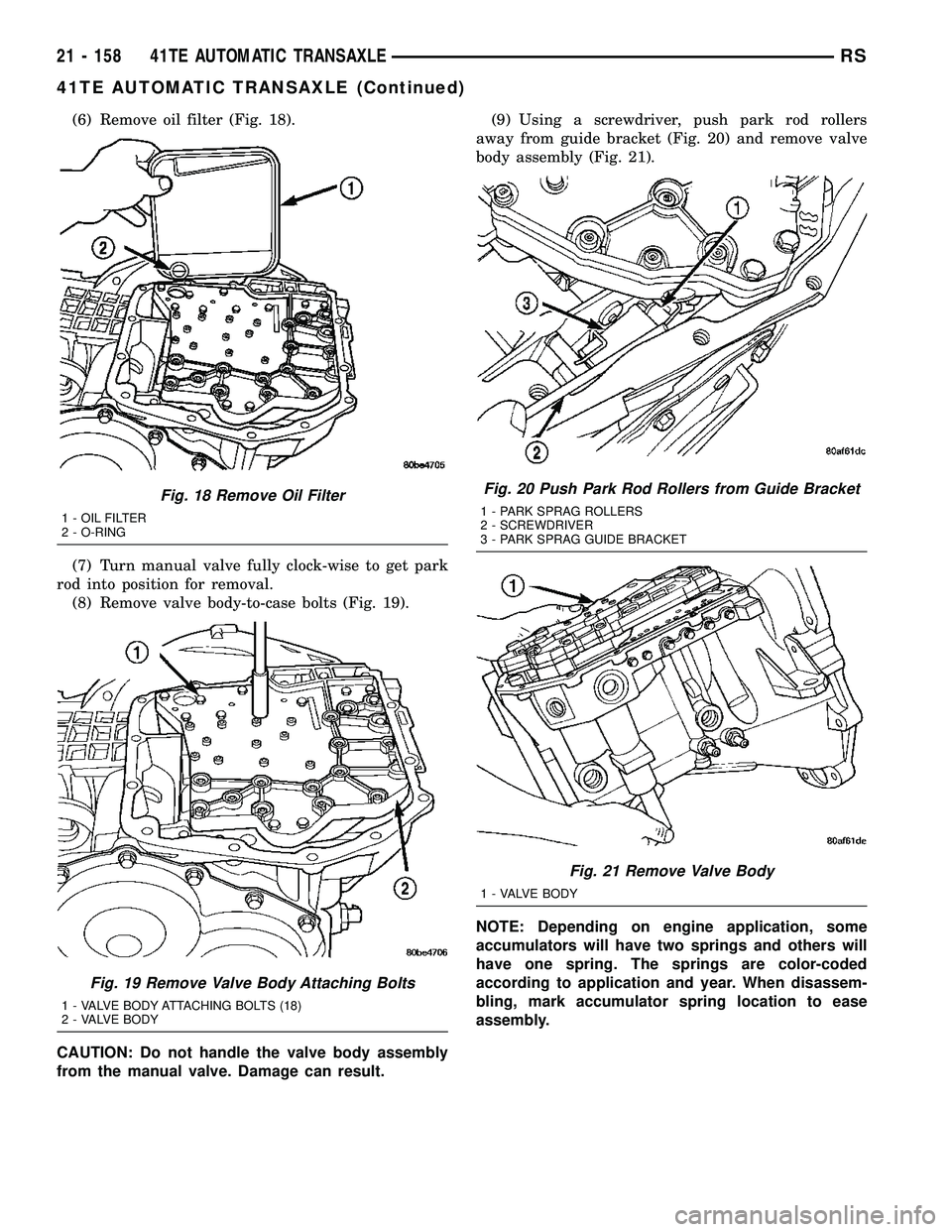
(6) Remove oil filter (Fig. 18).
(7) Turn manual valve fully clock-wise to get park
rod into position for removal.
(8) Remove valve body-to-case bolts (Fig. 19).
CAUTION: Do not handle the valve body assembly
from the manual valve. Damage can result.(9) Using a screwdriver, push park rod rollers
away from guide bracket (Fig. 20) and remove valve
body assembly (Fig. 21).
NOTE: Depending on engine application, some
accumulators will have two springs and others will
have one spring. The springs are color-coded
according to application and year. When disassem-
bling, mark accumulator spring location to ease
assembly.
Fig. 18 Remove Oil Filter
1 - OIL FILTER
2 - O-RING
Fig. 19 Remove Valve Body Attaching Bolts
1 - VALVE BODY ATTACHING BOLTS (18)
2 - VALVE BODY
Fig. 20 Push Park Rod Rollers from Guide Bracket
1 - PARK SPRAG ROLLERS
2 - SCREWDRIVER
3 - PARK SPRAG GUIDE BRACKET
Fig. 21 Remove Valve Body
1 - VALVE BODY
21 - 158 41TE AUTOMATIC TRANSAXLERS
41TE AUTOMATIC TRANSAXLE (Continued)
Page 1642 of 2339
(18) Install output gear stirrup with serrated side
out (Fig. 106).
(19) Install retaining strap.
(20) Install strap bolts but do not tighten at this
time (Fig. 107).(21) Rotate stirrup clockwise against flats of
retaining bolt (Fig. 108).
(22) Torque stirrup strap bolts to 23 N´m (200 in.
lbs.) (Fig. 109).
Fig. 106 Install Stirrup
1 - STIRRUP
2 - OUTPUT GEAR RETAINING BOLT
Fig. 107 Install Strap Bolts
1 - RETAINING STRAP
2 - STIRRUP
3 - RETAINING STRAP BOLTS
Fig. 108 Turn Stirrup Clockwise Against Bolt Flats
1 - RETAINING STRAP
2 - STIRRUP
Fig. 109 Tighten Stirrup Strap Bolts To 23 N´m (200
in.) lbs.)
1 - RETAINING STRAP
2 - STIRRUP
RS41TE AUTOMATIC TRANSAXLE21 - 181
41TE AUTOMATIC TRANSAXLE (Continued)
Page 1655 of 2339
(60) Install low/reverse accumulator plug (Fig.
150).
(61) Install low/reverse accumulator snap ring
(Fig. 151).
NOTE: Depending on engine application, some
accumulators will have two springs, and others will
have one spring. The springs are color-coded for
application and year.(62) Install underdrive and overdrive accumulators
(Fig. 152).
(63) Install valve body to transaxle (Fig. 153).
Rotate manual valve shaft fully clockwise to ease
installation. Make sure park rod rollers are posi-
tioned within park guide bracket.
Fig. 150 Install Low/Reverse Accumulator Plug
(Cover)
1 - ADJUSTABLE PLIERS
2 - PLUG
Fig. 151 Install Low/Reverse Accumulator Snap
Ring
1 - SNAP RING
2 - PLUG
Fig. 152 Underdrive and Overdrive Accumulators
1 - OVERDRIVE PISTON AND SPRING
2 - UNDERDRIVE PISTON AND SPRING
Fig. 153 Install Valve Body
1 - VALVE BODY
21 - 194 41TE AUTOMATIC TRANSAXLERS
41TE AUTOMATIC TRANSAXLE (Continued)
Page 1739 of 2339

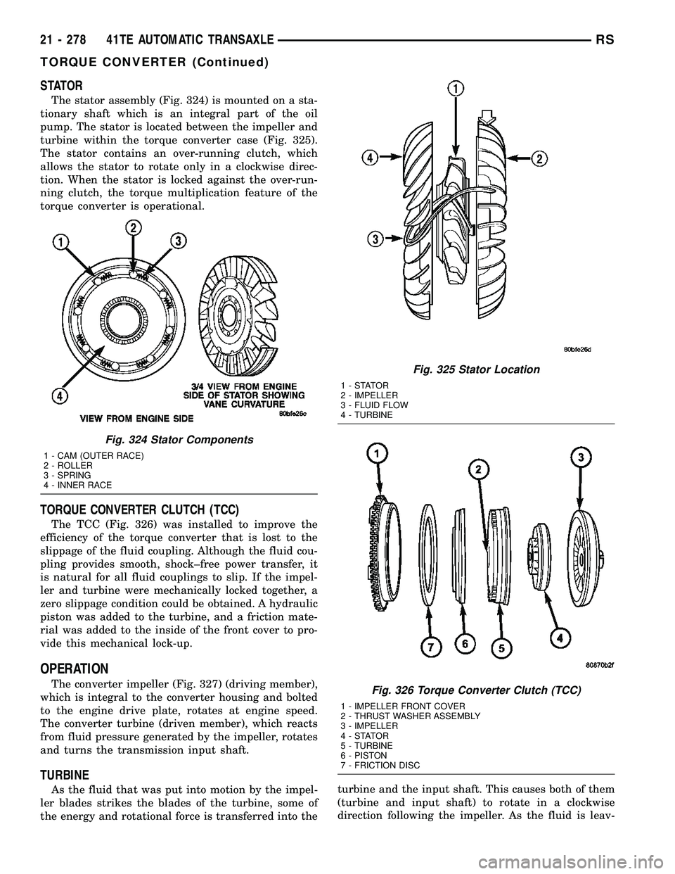
STATOR
The stator assembly (Fig. 324) is mounted on a sta-
tionary shaft which is an integral part of the oil
pump. The stator is located between the impeller and
turbine within the torque converter case (Fig. 325).
The stator contains an over-running clutch, which
allows the stator to rotate only in a clockwise direc-
tion. When the stator is locked against the over-run-
ning clutch, the torque multiplication feature of the
torque converter is operational.
TORQUE CONVERTER CLUTCH (TCC)
The TCC (Fig. 326) was installed to improve the
efficiency of the torque converter that is lost to the
slippage of the fluid coupling. Although the fluid cou-
pling provides smooth, shock±free power transfer, it
is natural for all fluid couplings to slip. If the impel-
ler and turbine were mechanically locked together, a
zero slippage condition could be obtained. A hydraulic
piston was added to the turbine, and a friction mate-
rial was added to the inside of the front cover to pro-
vide this mechanical lock-up.
OPERATION
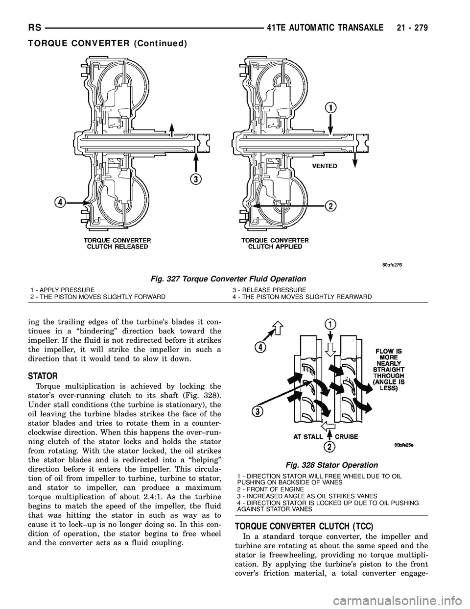
The converter impeller (Fig. 327) (driving member),
which is integral to the converter housing and bolted
to the engine drive plate, rotates at engine speed.
The converter turbine (driven member), which reacts
from fluid pressure generated by the impeller, rotates
and turns the transmission input shaft.
TURBINE
As the fluid that was put into motion by the impel-
ler blades strikes the blades of the turbine, some of
the energy and rotational force is transferred into theturbine and the input shaft. This causes both of them
(turbine and input shaft) to rotate in a clockwise
direction following the impeller. As the fluid is leav-
Fig. 324 Stator Components
1 - CAM (OUTER RACE)
2 - ROLLER
3 - SPRING
4 - INNER RACE
Fig. 325 Stator Location
1-STATOR
2 - IMPELLER
3 - FLUID FLOW
4 - TURBINE
Fig. 326 Torque Converter Clutch (TCC)
1 - IMPELLER FRONT COVER
2 - THRUST WASHER ASSEMBLY
3 - IMPELLER
4-STATOR
5 - TURBINE
6 - PISTON
7 - FRICTION DISC
21 - 278 41TE AUTOMATIC TRANSAXLERS
TORQUE CONVERTER (Continued)
Page 1740 of 2339

ing the trailing edges of the turbine's blades it con-
tinues in a ªhinderingº direction back toward the
impeller. If the fluid is not redirected before it strikes
the impeller, it will strike the impeller in such a
direction that it would tend to slow it down.
STATOR
Torque multiplication is achieved by locking the
stator's over-running clutch to its shaft (Fig. 328).
Under stall conditions (the turbine is stationary), the
oil leaving the turbine blades strikes the face of the
stator blades and tries to rotate them in a counter-
clockwise direction. When this happens the over±run-
ning clutch of the stator locks and holds the stator
from rotating. With the stator locked, the oil strikes
the stator blades and is redirected into a ªhelpingº
direction before it enters the impeller. This circula-
tion of oil from impeller to turbine, turbine to stator,
and stator to impeller, can produce a maximum
torque multiplication of about 2.4:1. As the turbine
begins to match the speed of the impeller, the fluid
that was hitting the stator in such as way as to
cause it to lock±up is no longer doing so. In this con-
dition of operation, the stator begins to free wheel
and the converter acts as a fluid coupling.
TORQUE CONVERTER CLUTCH (TCC)
In a standard torque converter, the impeller and
turbine are rotating at about the same speed and the
stator is freewheeling, providing no torque multipli-
cation. By applying the turbine's piston to the front
cover's friction material, a total converter engage-
Fig. 327 Torque Converter Fluid Operation
1 - APPLY PRESSURE 3 - RELEASE PRESSURE
2 - THE PISTON MOVES SLIGHTLY FORWARD 4 - THE PISTON MOVES SLIGHTLY REARWARD
Fig. 328 Stator Operation
1 - DIRECTION STATOR WILL FREE WHEEL DUE TO OIL
PUSHING ON BACKSIDE OF VANES
2 - FRONT OF ENGINE
3 - INCREASED ANGLE AS OIL STRIKES VANES
4 - DIRECTION STATOR IS LOCKED UP DUE TO OIL PUSHING
AGAINST STATOR VANES
RS41TE AUTOMATIC TRANSAXLE21 - 279
TORQUE CONVERTER (Continued)
Page 1746 of 2339
(7) Remove oil filter (Fig. 337).
(8) Remove the valve body-to-transaxle case bolts
(Fig. 338).
NOTE: To ease removal of the valve body, turn the
manual valve lever fully clockwise to low or first
gear.(9) Remove park rod rollers from guide bracket
and remove valve body from transaxle (Fig. 339) (Fig.
340).
CAUTION: The valve body manual shaft pilot may
distort and bind the manual valve if the valve body
is mishandled or dropped.
Fig. 337 Oil Filter
1 - OIL FILTER
2 - O-RING
Fig. 338 Valve Body Attaching Bolts
1 - VALVE BODY ATTACHING BOLTS (18)
2 - VALVE BODY
Fig. 339 Push Park Rod Rollers from Guide Bracket
1 - PARK SPRAG ROLLERS
2 - SCREWDRIVER
3 - PARK SPRAG GUIDE BRACKET
Fig. 340 Valve Body Removal/Installation
1 - VALVE BODY
RS41TE AUTOMATIC TRANSAXLE21 - 285
VALVE BODY (Continued)