2005 CHRYSLER CARAVAN key
[x] Cancel search: keyPage 1948 of 2339
SUNROOF
TABLE OF CONTENTS
page page
SUNROOF
DESCRIPTION........................169
DIAGNOSIS AND TESTING
SUNROOF DIAGNOSIS AND TESTING....169
DRAIN TUBE
REMOVAL............................172
INSTALLATION........................172
GLASS PANEL
REMOVAL............................173
INSTALLATION........................173
ADJUSTMENTS
SUNROOF GLASS PANEL ADJUSTMENT . . 173
SUNROOF ASSEMBLY
REMOVAL............................173
INSTALLATION........................173
SUNSHADE
REMOVAL............................173INSTALLATION........................173
WIND DEFLECTOR
REMOVAL............................174
INSTALLATION........................174
WATER CHANNEL
REMOVAL............................174
INSTALLATION........................174
SUNROOF MOTOR
REMOVAL............................174
INSTALLATION........................174
ADJUSTMENTS
ADJUSTMENT.......................175
SUNROOF SWITCH
REMOVAL............................176
INSTALLATION........................176
SUNROOF
DESCRIPTION
WARNING: Keep fingers and other body parts out
of sunroof opening at all times.
The sun roof features consists of: (Fig. 1)
²Sun roof glass
²Sun roof sun shade
The sunroof power sliding glass panel and sun-
shade can be positioned anywhere along its travel,
rearward of glass panel front edge.
The sunroof is electrically operated from a switch
located in the overhead console. To operate the sun-
roof the ignition switch must be in the Accessory or
On/Run position. Both switchs are a rocker style
design that open or close the sunroof. When pressing
and releasing the open button once, the sunroof will
express open to the comfort stop and the wind deflec-
tor will raise. If the button is pressed a second time,
the sunroof will continue to open to full travel unless
the button is released, at which time it will stop in
that position. Pressing and holding the close button
will close the sunroof. If the close button is released
before the glass fully closes, the sunroof will stop in
that position. The vent switch operates in a similar
manor. The sunroof will also operate for up to fifteen
minutes after the ignition key is turned off for cus-
tomer comfort and convenance while parking.
DIAGNOSIS AND TESTING
SUNROOF DIAGNOSIS AND TESTING
Refer to Sunroof Diagnostic Chart for possible
causes. Before beginning sunroof diagnostics verify
that all other power accessories are in proper operat-
ing condition. If not, a common electrical problem
may exist. Refer to Wiring Diagrams, in this publica-
tion for circuit, splice and component descriptions.
Check the condition of the circuit protection (20 amp
circuit breaker in the Junction Block). Inspect all
wiring connector pins for proper engagement and
continuity. Check for battery voltage at the power
sunroof controller, refer to Wiring Diagrams, for cir-
cuit information. If battery voltage of more than 10
volts is detected at the controller, proceed with the
following tests (the controller will not operate at less
than 10 volts).
Before beginning diagnosis for wind noise or water
leaks, verify that the problem was not caused by
releasing the control switch before the sunroof was
fully closed. The sunroof module has a water-man-
agement system. If however, the sunroof glass is in a
partial closed position, high pressure water may be
forced beyond the water management system bound-
aries and onto the headlining.
RSSUNROOF23 - 169
Page 2156 of 2339
MANUAL DUAL ZONE
²The two slide controls enable continuously vari-
able proportioning of the conditioned air.
²The mode control knob enables continuously
variable proportioning of air flow between modes and
has detents adjacent to each icon.
²The blower control provides four separate speeds
and an Off position.
²When the heater-A/C system is off, the HVAC
computer closes the recirculation door to prevent out-
side air from entering the passenger compartment.
²Interior air may be recirculated to speed up
heating or cooling in all modes except defrost and
mix by pressing the Recirculate button on the A/C-
heater control.
²To reduce humidity for rapid defogging, the A/C
compressor runs automatically in modes from ªmixº
to full defrost when outside temperatures are above
freezing.
²Air conditioning is available in any mode by
pressing the snowflake, A/C on/off button.
MANUAL THREE ZONE
FRONT CONTROL PANEL
²Primary control of the rear heater-A/C system is
on the instrument panel. This control allows the
driver to set the rear compartment fan speed, to turn
the rear heater-A/C system off, or to give control to
the intermediate seat occupants by switching to the
Rear position. When the rear heater-A/C system is
controlled from the instrument panel, rear air tem-
perature is based on the driver-side temperature con-
trol position, and the mode (floor or overhead air) is
based on the front control's mode position.
²The mode control knob enables continuously
variable proportioning of air flow between modes but
has detents adjacent to each icon.
²The blower control provides four separate speeds
and an Off position. When the heater-A/C system is
off, the HVAC computer closes the recirculation door
to prevent outside air from entering the passenger
compartment.
²Interior air may be recirculated to speed up
heating or cooling in all modes except defrost and
mix by pressing the Recirculate button on the control
panel.
²To reduce humidity for rapid defogging the A/C
compressor runs automatically in modes from ªmix'
to full defrost when outside temperatures are above
freezing.
²Air conditioning is available in any mode by
pressing the snowflake, A/C on/off, button.
REAR CONTROL PANEL
With the rear control active, temperature selection
dictates the air distribution mode (floor or overhead
air) of the rear unit: a cool temperature setting
directs flow to the overhead outlets and a warm tem-
perature setting to the floor.
AUTOMATIC TEMPERATURE CONTROL
Comfort temperature or perceived temperature is
affected by air flow, sun levels on exposed skin, etc.
The air temperature may be higher or lower than the
comfort temperature. The automatic temperature
control (ATC) system uses two infrared sensors in the
instrument panel center stack to measure the tem-
perature of the front occupants in order determine
their comfort level relative to their selected comfort
temperature. The integral HVAC computer adjusts
temperature and air flow rates to maintain the cus-
tomer-perceived comfort temperatures. The air tem-
perature in the passenger compartment may be
slightly higher or lower than the comfort tempera-
ture at any time. For instance, on sunny summer
days the air flow will probably be cooler than the
comfort temperature; on cold or cloudy days and at
night it will probably be slightly warmer.
The Three-Zone ATC system uses the infrared sen-
sors located in the instrument panel center stack
along with an offset calibration strategy to meet the
comfort requirements of the rear seat occupants.
FRONT CONTROL PANEL
²AUTO HI/LO± This system features two sets of
automatic control logic that allow either a rapid cool-
down rate or a somewhat slower cool-down rate with
less fan noise. HI-AUTO controls the system to reach
its assigned temperature quickly with a higher fan
speed. LO-AUTO controls the system to reach its
assigned temperature somewhat slower with less fan
noise. Both modes will automatically engage auto
recirculation.
²DEFROST± The defrost function must be man-
ually selected to direct air flow to the windshield to
remove fog or ice. The ATC system cannot automati-
cally sense the presence of fog or ice on the wind-
shield.
²RECIRC± The RECIRC button will close the
air inlet door. If the system is in auto recirc (indica-
tor being displayed automatically), pressing the man-
ual recirc button will disable the auto recirc function
until one of the auto keys are pressed or the ignition
is cycled. If Auto HI/LO is pressed while manual
recirc is active, manual recirc will be deactivated.
²REAR WINDOW DEFOGGER± Pushing the
button sends a PCI bus message to the intelligent
power module which controls the rear window defog-
ger and side view mirror (if equipped) circuitry. The
RSHEATING & AIR CONDITIONING24-5
HEATING & AIR CONDITIONING (Continued)
Page 2270 of 2339
NOTE: Verify that there is more than 1/8 of a tank of
fuel in the vehicle's fuel tank before performing this
procedure. Add fuel, if necessary.
NOTE: Failure to prime the dosing pump after drain-
ing the supplemental cabin fuel line will prevent
cabin heater activation during the first attempt to
start the cabin heater. This will also set a diagnostic
trouble code (DTC) in the cabin heater control's
memory. Do not perform the Dosing Pump Priming
procedure if an attempt was made to start the cabin
heater without priming the dosing pump first. This
will put excess fuel in the cabin heater and cause
smoke to emit from the cabin heater exhaust pipe
when cabin heater activation occurs.
(7) Connect the DRBIIItscan tool to the diagnos-
tic link connector.
(8) Turn the ignition to the ON position.
NOTE: Do not activate the dosing pump prime more
than one time. This will put excess fuel in the sup-
plemental cabin heater and cause smoke to emit
from the cabin heater exhaust pipe when cabin
heater activation occurs.
NOTE: A clicking noise heard coming from the dos-
ing pump indicates that the pump is operational.
(9) With the DRBIIItscan tool in Cabin Heater,
select System Tests and Dosing Pump Prime. Allow
the dosing pump to run for the full 45 second cycle
time. When the 45 second cycle is complete, press
Page Back on the DRBIIItscan tool key pad to exit
the Dosing Pump Prime. The Dosing Pump Priming
procedure is now complete.
HEATER HOSES
REMOVAL
(1) Raise and support the vehicle. Take note of the
location of the flexible section of the cabin heater
exhaust tube.
(2) Drain the engine cooling system (Refer to 7 -
COOLING - STANDARD PROCEDURE).
NOTE: Complete removal of the supplemental cabin
heater from vehicle is not required, lowering the
cabin heater allows easier access to coolant line
clamps.(3) Lower the supplemental cabin heater from the
vehicle (Refer to 24 - HEATING & AIR CONDITION-
ING/CABIN HEATER/HEATER UNIT - REMOVAL).
(4) Remove the clamps from both flexible coolant
line ends.
NOTE: It is recommended that both flexible cabin
heater coolant lines be replaced if either cabin
heater coolant line is damaged.
(5) Remove both coolant lines from vehicle.
INSTALLATION
(1) Install both flexible coolant lines to the supple-
mental cabin heater and install the clamps.
(2) Install the flexible coolant lines to the coolant
pipes and install the clamps.
(3) Install the supplemental cabin heater into the
vehicle (Refer to 24 - HEATING & AIR CONDITION-
ING/CABIN HEATER/HEATER UNIT - INSTALLA-
TION).
(4) Lower the vehicle.
(5) Fill the engine cooling system (Refer to 7 -
COOLING - STANDARD PROCEDURE).
(6) Verify operation of the supplemental cabin
heater.
HEATER PIPES
REMOVAL
WARNING: ALLOW THE ENGINE COOLING SYSTEM
TO COOL COMPLETELY BEFORE REMOVING RADI-
ATOR CAP OR DRAINING THE ENGINE COOLING
SYSTEM. PERSONAL INJURY MAY RESULT IF THE
ENGINE COOLING SYSTEM IS OPENED WHILE
ENGINE COOLANT IS HOT AND UNDER PRES-
SURE.
NOTE: Steel heater lines from engine compartment
to the supplemental cabin heater are part of an
assembly that includes the air intake pipe. If the
cabin heater lines or air intake pipe require removal
or replacement the entire cabin heater assembly
will require removal or replacement.
(1) Drain the engine cooling system (Refer to 7 -
COOLING - STANDARD PROCEDURE).
(2) Remove clamps from both the EGR cooler and
the lower heater port. Separate hoses from the mat-
ing plumbing port (Fig. 6).
RSCABIN HEATER24 - 119
FUEL LINE (Continued)
Page 2277 of 2339
OXYGEN SENSOR HEATER MONITOR (SBEC)
DESCRIPTIONÐIf there is an oxygen sensor
(O2S) DTC as well as a O2S heater DTC, the O2S
heater fault MUST be repaired first. After the O2S
fault is repaired, verify that the heater circuit is
operating correctly.
The voltage readings taken from the O2S are very
temperature sensitive. The readings are not accurate
below 300ÉC. Heating of the O2S is done to allow the
engine controller to shift to closed loop control as
soon as possible. The heating element used to heat
the O2S must be tested to ensure that it is heating
the sensor properly.
The heater element itself is not tested directly. The
sensor output is used to test the heater by isolating
the effect of the heater element on the O2S output
voltage from the other effects. The resistance is nor-
mally between 100 ohms and 4.5 megaohms. When
oxygen sensor temperature increases, the resistance
in the internal circuit decreases. The PCM sends a 5
volts biased signal through the oxygen sensors to
ground this monitoring circuit. As the temperature
increases, resistance decreases and the PCM detects
a lower voltage at the reference signal. Inversely, as
the temperature decreases, the resistance increases
and the PCM detects a higher voltage at the refer-
ence signal. The O2S circuit is monitored for a drop
in voltage.
OPERATIONÐThe Oxygen Sensor Heater Moni-
tor begins after the ignition has been turned OFF
and the O2 sensors have cooled. The PCM sends a 5
volt bias to the oxygen sensor every 1.6 seconds. The
PCM keeps it biased for 35 ms each time. As the sen-
sor cools down, the resistance increases and the PCM
reads the increase in voltage. Once voltage has
increased to a predetermined amount, higher than
when the test started, the oxygen sensor is cool
enough to test heater operation.
When the oxygen sensor is cool enough, the PCM
energizes the ASD relay. Voltage to the O2 sensor
begins to increase the temperature. As the sensor
temperature increases, the internal resistance
decreases. The PCM continues biasing the 5 volt sig-
nal to the sensor. Each time the signal is biased, the
PCM reads a voltage decrease. When the PCM
detects a voltage decrease of a predetermined value
for several biased pulses, the test passes.
The heater elements are tested each time the
engine is turned OFF if all the enabling conditions
are met. If the monitor fails, the PCM stores a
maturing fault and a Freeze Frame is entered. If two
consecutive tests fail, a DTC is stored. Because the
ignition is OFF, the MIL is illuminated at the begin-
ning of the next key cycle, after the 2nd failure.Enabling ConditionsÐThe following conditions
must be met for the PCM to run the oxygen sensor
heater test:
²Engine run time of at least 5.1 minutes
²Key OFF power down
²Battery voltage of at least 10 volts
²Sufficient Oxygen Sensor cool down
Pending ConditionsÐThere are not conditions or
situations that prompt conflict or suspension of test-
ing. The oxygen sensor heater test is not run pending
resolution of MIL illumination due to oxygen sensor
failure.
SuspendÐThere are no conditions which exist for
suspending the Heater Monitor.
CATALYST MONITOR
To comply with clean air regulations, vehicles are
equipped with catalytic converters. These converters
reduce the emission of hydrocarbons, oxides of nitro-
gen and carbon monoxide.
Normal vehicle miles or engine misfire can cause a
catalyst to decay. A meltdown of the ceramic core can
cause a reduction of the exhaust passage. This can
increase vehicle emissions and deteriorate engine
performance, driveability and fuel economy.
The catalyst monitor uses dual oxygen sensors
(O2S's) to monitor the efficiency of the converter. The
dual O2S strategy is based on the fact that as a cat-
alyst deteriorates, its oxygen storage capacity and its
efficiency are both reduced. By monitoring the oxy-
gen storage capacity of a catalyst, its efficiency can
be indirectly calculated. The upstream O2S is used to
detect the amount of oxygen in the exhaust gas
before the gas enters the catalytic converter. The
PCM calculates the A/F mixture from the output of
the O2S. A low voltage indicates high oxygen content
(lean mixture). A high voltage indicates a low content
of oxygen (rich mixture).
When the upstream O2S detects a high oxygen
condition, there is an abundance of oxygen in the
exhaust gas. A functioning converter would store this
oxygen so it can use it for the oxidation of HC and
CO. As the converter absorbs the oxygen, there will
be a lack of oxygen downstream of the converter. The
output of the downstream O2S will indicate limited
activity in this condition.
As the converter loses the ability to store oxygen,
the condition can be detected from the behavior of
the downstream O2S. When the efficiency drops, no
chemical reaction takes place. This means the con-
centration of oxygen will be the same downstream as
upstream. The output voltage of the downstream
O2S copies the voltage of the upstream sensor. The
only difference is a time lag (seen by the PCM)
between the switching of the O2S's.
25 - 4 EMISSIONS CONTROLRS
EMISSIONS CONTROL (Continued)
Page 2299 of 2339
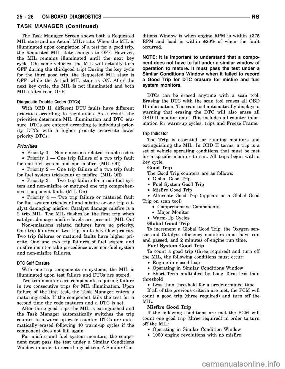
The Task Manager Screen shows both a Requested
MIL state and an Actual MIL state. When the MIL is
illuminated upon completion of a test for a good trip,
the Requested MIL state changes to OFF. However,
the MIL remains illuminated until the next key
cycle. (On some vehicles, the MIL will actually turn
OFF during the thirdgood trip) During the key cycle
for the third good trip, the Requested MIL state is
OFF, while the Actual MIL state is ON. After the
next key cycle, the MIL is not illuminated and both
MIL states read OFF.
Diagnostic Trouble Codes (DTCs)
With OBD II, different DTC faults have different
priorities according to regulations. As a result, the
priorities determine MIL illumination and DTC era-
sure. DTCs are entered according to individual prior-
ity. DTCs with a higher priority overwrite lower
priority DTCs.
Priorities
²Priority 0 ÐNon-emissions related trouble codes.
²Priority 1 Ð One trip failure of a two trip fault
for non-fuel system and non-misfire. (MIL Off)
²Priority 2 Ð One trip failure of a two trip fault
for fuel system (rich/lean) or misfire. (MIL Off)
²Priority3ÐTwotrip failure for a non-fuel sys-
tem and non-misfire or matured one trip comprehen-
sive component fault. (MIL On)
²Priority4ÐTwotrip failure or matured fault
for fuel system (rich/lean) and misfire or one trip cat-
alyst damaging misfire. Catalyst damage misfire is a
2 trip MIL. The MIL flashes on the first trip when
catalyst damage misfire levels are present. (MIL On)
Non-emissions related failures have no priority.
One trip failures of two trip faults have low priority.
Two trip failures or matured faults have higher pri-
ority. One and two trip failures of fuel system and
misfire monitor take precedence over non-fuel system
and non-misfire failures.
DTC Self Erasure
With one trip components or systems, the MIL is
illuminated upon test failure and DTCs are stored.
Two trip monitors are components requiring failure
in two consecutive trips for MIL illumination. Upon
failure of the first test, the Task Manager enters a
maturing code. If the component fails the test for a
second time the code matures and a DTC is set.
After three good trips the MIL is extinguished and
the Task Manager automatically switches the trip
counter to a warm-up cycle counter. DTCs are auto-
matically erased following 40 warm-up cycles if the
component does not fail again.
For misfire and fuel system monitors, the compo-
nent must pass the test under a Similar Conditions
Window in order to record a good trip. A Similar Con-ditions Window is when engine RPM is within 375
RPM and load is within 20% of when the fault
occurred.
NOTE: It is important to understand that a compo-
nent does not have to fail under a similar window of
operation to mature. It must pass the test under a
Similar Conditions Window when it failed to record
a Good Trip for DTC erasure for misfire and fuel
system monitors.
DTCs can be erased anytime with a scan tool.
Erasing the DTC with the scan tool erases all OBD
II information. The scan tool automatically displays a
warning that erasing the DTC will also erase all
OBD II monitor data. This includes all counter infor-
mation for warm-up cycles, trips and Freeze Frame.
Trip Indicator
TheTripis essential for running monitors and
extinguishing the MIL. In OBD II terms, a trip is a
set of vehicle operating conditions that must be met
for a specific monitor to run. All trips begin with a
key cycle.
Good Trip
The Good Trip counters are as follows:
²Global Good Trip
²Fuel System Good Trip
²Misfire Good Trip
²Alternate Good Trip (appears as a Global Good
Trip on scan tool)
²Comprehensive Components
²Major Monitor
²Warm-Up Cycles
Global Good Trip
To increment a Global Good Trip, the Oxygen sen-
sor and Catalyst efficiency monitors must have run
and passed, and 2 minutes of engine run time.
Fuel System Good Trip
To count a good trip (three required) and turn off
the MIL, the following conditions must occur:
²Engine in closed loop
²Operating in Similar Conditions Window
²Short Term multiplied by Long Term less than
threshold
²Less than threshold for a predetermined time
If all of the previous criteria are met, the PCM will
count a good trip (three required) and turn off the
MIL.
Misfire Good Trip
If the following conditions are met the PCM will
count one good trip (three required) in order to turn
off the MIL:
²Operating in Similar Condition Window
²1000 engine revolutions with no misfire
25 - 26 ON-BOARD DIAGNOSTICSRS
TASK MANAGER (Continued)
Page 2308 of 2339
CHIRP PREFERENCE - STANDARDPROCEDURE, HORN .................. 8N-24
CIRCUIT, DIAGNOSIS AND TESTING - AMBIENT TEMPERATURE SENSOR ......8M-12
CIRCUIT FUNCTIONS - DESCRIPTION . . 8W-01-6
CIRCUIT INFORMATION - DESCRIPTION . 8W-01-5
CIRCUIT RESISTANCE TEST - DIAGNOSIS AND TESTING, FEED ........8F-35
CIRCUIT TEST - DIAGNOSIS AND TESTING, CONTROL .................. 8F-33
CIRCUIT TEST - DIAGNOSIS AND TESTING, FEED ...................... 8F-36
CIRCUITS AND VALVES - OPERATION, HYDRAULIC .......................... 5-95
CIRCUITS, DESCRIPTION - NON- MONITORED ......................... 25-5
CLAMP - STANDARD PROCEDURE, HOSES .............................. 14-7
CLAMPS - DESCRIPTION, FUEL LINES/HOSES ........................ 14-7
CLAMPS - DESCRIPTION, HOSE ...........7-1
CLAMPS - OPERATION, HOSE .............7-2
CLASSIFICATION MODULE - DESCRIPTION, OCCUPANT .............8O-25
CLASSIFICATION MODULE - INSTALLATION, OCCUPANT ............8O-26
CLASSIFICATION MODULE - OPERATION, OCCUPANT ......................... 8O-25
CLASSIFICATION MODULE - REMOVAL, OCCUPANT ......................... 8O-26
CLEARANCE - STANDARD PROCEDURE, MEASURING CONNECTING ROD
BEARING ............................ 9-123
CLEARANCE USING PLASTIGAGE - STANDARD PROCEDURE, MEASURING
BEARING ........................ 9-12,9-86
CLOCKSPRING - DESCRIPTION .........8O-10
CLOCKSPRING - INSTALLATION .........8O-12
CLOCKSPRING - OPERATION ...........8O-11
CLOCKSPRING - REMOVAL ............8O-12
CLOCKSPRING CENTERING - STANDARD PROCEDURE ........................ 8O-11
CLUSTER - DESCRIPTION, INSTRUMENT . . . 8J-1
CLUSTER - OPERATION, INSTRUMENT .....8J-1
CLUSTER BEZEL - INSTALLATION ........23-65
CLUSTER BEZEL - REMOVAL ...........23-65
CLUSTER DIAGNOSIS - DIAGNOSIS AND TESTING ............................ 8J-3
CLUSTER ILLUMINATION LAMPS - INSTALLATION ....................... 8L-21
CLUSTER ILLUMINATION LAMPS - REMOVAL .......................... 8L-21
CLUSTER LENS - INSTALLATION ........8J-11
CLUSTER LENS - REMOVAL ............8J-11
CLUTCH AIR PRESSURE TESTS - DIAGNOSIS AND TESTING ........21-153,21-8
CLUTCH ASSEMBLY - ASSEMBLY, INPUT ....................... 21-246,21-95
CLUTCH ASSEMBLY - DISASSEMBLY, INPUT ....................... 21-237,21-86
CLUTCH BREAK-IN, STANDARD PROCEDURE - A/C ................... 24-15
CLUTCH COIL, DIAGNOSIS AND TESTING - A/C COMPRESSOR .................. 24-14
CLUTCH INSPECTION, STANDARD PROCEDURE ........................ 24-15
CLUTCH RELAY - DESCRIPTION, A/C COMPRESSOR ....................... 24-18
CLUTCH RELAY - INSTALLATION, A/C COMPRESSOR ....................... 24-19
CLUTCH RELAY - OPERATION, A/C COMPRESSOR ....................... 24-18
CLUTCH RELAY - REMOVAL, A/C COMPRESSOR ....................... 24-19
CLUTCH/COIL - DESCRIPTION, A/C COMPRESSOR ....................... 24-13
CLUTCH/COIL - OPERATION, A/C COMPRESSOR ....................... 24-13
CLUTCHES - DESCRIPTION, DRIVING . . . 21-219,
21-74
CLUTCHES - DESCRIPTION, HOLDING . . . 21-236,
21-86
CLUTCHES - OPERATION, DRIVING .....21-219,
21-74
CLUTCHES - OPERATION, HOLDING ....21-236,
21-86
COAT/CLEARCOAT FINISH - DESCRIPTION, BASE .................23-101CODE - DESCRIPTION, PAINT
..........23-101
CODE CHARTS - SPECIFICATIONS, COLOR ............................ 23-100
CODES - STANDARD PROCEDURE, OBTAINING DIAGNOSTIC TROUBLE ......8E-15
CODES, STANDARD PROCEDURE - ERASING TRANSMITTER ..............8M-12
CODES, STANDARD PROCEDURE - SETTING TRANSMITTER ..............8M-12
COIL - DESCRIPTION, IGNITION ..........8I-6
COIL - OPERATION, IGNITION ............8I-6
COIL, DIAGNOSIS AND TESTING - A/C COMPRESSOR CLUTCH ...............24-14
COLLAR - INSTALLATION, STRUCTURAL . . . 9-49
COLLAR - REMOVAL, STRUCTURAL .......9-49
COLOR CODE CHARTS - SPECIFICATIONS .................... 23-100
COLUMN - DESCRIPTION, STEERING .....19-10
COLUMN - DIAGNOSIS AND TESTING, STEERING .......................... 19-11
COLUMN COVER - INSTALLATION, LOWER STEERING ................... 23-74
COLUMN COVER - INSTALLATION, OVER STEERING .......................... 23-76
COLUMN COVER - REMOVAL, LOWER STEERING .......................... 23-74
COLUMN COVER - REMOVAL, OVER STEERING .......................... 23-76
COLUMN FASTENER TORQUE, SPECIFICATIONS ..................... 19-17
COMBUSTION PRESSURE LEAKAGE TEST - DIAGNOSIS AND TESTING,
CYLINDER ........................ 9-85,9-9
COMMUNICATION RECEIVE - PCM INPUT - OPERATION, DATA BUS ..............8E-14
COMMUNICATIONS INTERFACE (PCI) BUS, OPERATION - PROGRAMMABLE ....14-25
COMPASS CALIBRATION, STANDARD PROCEDURE ......................... 8M-4
COMPASS DEMAGNETIZING, STANDARD PROCEDURE ......................... 8M-5
COMPASS MINI-TRIP COMPUTER, DIAGNOSIS AND TESTING .............8M-10
COMPASS VARIATION ADJUSTMENT, STANDARD PROCEDURE ...............8M-5
COMPASS/MINI-TRIP COMPUTER - DESCRIPTION ....................... 8M-10
COMPASS/MINI-TRIP COMPUTER - OPERATION ........................ 8M-10
COMPRESSION PRESSURE TEST - DIAGNOSIS AND TESTING, CYLINDER . . 9-85,9-9
COMPRESSOR CLUTCH COIL, DIAGNOSIS AND TESTING - A/ C.........24-14
COMPRESSOR CLUTCH RELAY - DESCRIPTION, A/C ................... 24-18
COMPRESSOR CLUTCH RELAY - INSTALLATION, A/C ................... 24-19
COMPRESSOR CLUTCH RELAY - OPERATION, A/C ..................... 24-18
COMPRESSOR CLUTCH RELAY - REMOVAL, A/C ...................... 24-19
COMPRESSOR CLUTCH/COIL - DESCRIPTION, A/C ................... 24-13
COMPRESSOR CLUTCH/COIL - OPERATION, A/C ..................... 24-13
COMPRESSOR, DESCRIPTION - A/C ......24-72
COMPRESSOR, INSTALLATION - A/C .....24-74
COMPRESSOR MOUNTING BRACKET, 2.4L ENGINE - A/C ..............24-74,24-75
COMPRESSOR NOISE DIAGNOSIS, DIAGNOSIS AND TESTING - A/C .........24-72
COMPRESSOR, OPERATION - A/C ........24-72
COMPRESSOR, REMOVAL - A/C .........24-73
COMPUTER - DESCRIPTION, COMPASS/ MINI-TRIP ......................... 8M-10
COMPUTER - OPERATION, COMPASS/ MINI-TRIP ......................... 8M-10
COMPUTER, DIAGNOSIS AND TESTING - COMPASS MINI-TRIP .................8M-10
CONCENTRATION TESTING - DIAGNOSIS AND TESTING, COOLANT ...............7-19
CONDENSER - DESCRIPTION, A/C .......24-75
CONDENSER - OPERATION, A/C .........24-75
CONDITION CHECK, STANDARD PROCEDURE - FLUID LEVEL ......21-230,21-82
CONDITIONER, DESCRIPTION - HEATER AND AIR ............................ 24-1CONDITIONER, OPERATION - HEATER
AND AIR ............................ 24-4
CONNECT FITTING DISASSEMBLY/ ASSEMBLY - STANDARD PROCEDURE,
TRANSMISSION COOLER LINE QUICK .....7-38
CONNECTING ROD - DESCRIPTION, PISTON ........................ 9-119,9-44
CONNECTING ROD - INSTALLATION, PISTON ............................. 9-45
CONNECTING ROD - REMOVAL, PISTON . . . 9-44
CONNECTING ROD BEARING CLEARANCE - STANDARD
PROCEDURE, MEASURING .............9-123
CONNECTING ROD, FITTING .............9-46
CONNECTING RODS - STANDARD PROCEDURE, FITTING .................9-119
CONNECTOR - DESCRIPTION, DATA LINK . . 8E-6
CONNECTOR - INSTALLATION .......8W-01-11
CONNECTOR - OPERATION, DATA LINK ....8E-6
CONNECTOR - REMOVAL ...........8W-01-11
CONNECTOR, GROUND AND SPLICE INFORMATION - DESCRIPTION ........8W-01-7
CONNECTOR/GROUND/SPLICE LOCATION - DESCRIPTION ....................8W -91-1
CONSOLE - DESCRIPTION, OVERHEAD ....8M-2
CONSOLE - FOLD-IN-FLOOR - INSTALLATION, FLOOR ................23-89
CONSOLE - FOLD-IN-FLOOR - REMOVAL, FLOOR ............................. 23-89
CONSOLE - INSTALLATION, LOWER ......23-73
CONSOLE - REMOVAL, LOWER ..........23-73
CONSOLE BASE TRAY - INSTALLATION, FLOOR ............................. 23-89
CONSOLE BASE TRAY - REMOVAL, FLOOR ............................. 23-89
CONSOLE, DIAGNOSIS AND TESTING - OVERHEAD .......................... 8M-3
CONSOLE KEY LOCK TUMBLER - FOLD-IN-FLOOR - INSTALLATION,
FLOOR ............................. 23-90
CONSOLE KEY LOCK TUMBLER - FOLD-IN-FLOOR - REMOVAL, FLOOR .....23-90
CONSOLE LAMP - INSTALLATION, CENTER ............................ 8L-21
CONSOLE LAMP - REMOVAL, CENTER ....8L-21
CONSOLE LAMP SWITCH - INSTALLATION, CENTER ...............8L-21
CONSOLE LAMP SWITCH - REMOVAL, CENTER ............................ 8L-21
CONSOLE LID LATCH - FOLD-IN-FLOOR - INSTALLATION, FLOOR ................23-90
CONSOLE LID LATCH - FOLD-IN-FLOOR - REMOVAL, FLOOR .................... 23-90
CONSOLE, SPECIAL TOOLS - OVERHEAD . . 8M-7
CONTAINER - DESCRIPTION, COOLANT RECOVERY .......................... 7-20
CONTAINER - INSTALLATION, COOLANT RECOVERY .......................... 7-20
CONTAINER - OPERATION, COOLANT RECOVERY .......................... 7-20
CONTAINER - REMOVAL, COOLANT RECOVERY .......................... 7-20
CONTAMINATION - DIAGNOSIS AND TESTING, BRAKE FLUID ................5-33
CONTINUITY - STANDARD PROCEDURE, TESTING .........................8W -01-9
CONTROL (4 SPEED EATX ONLY) - OPERATION, INTERACTIVE SPEED ........8P-2
CONTROL ARM - DESCRIPTION, LOWER . . . 2-12
CONTROL ARM - INSPECTION, LOWER ....2-14
CONTROL ARM - INSTALLATION, LOWER . . 2-15
CONTROL ARM - OPERATION, LOWER .....2-12
CONTROL ARM - REMOVAL, LOWER ......2-12
CONTROL ARM (REAR BUSHING - HYDRO) - ASSEMBLY, LOWER ...........2-15
CONTROL ARM (REAR BUSHING - HYDRO) - DISASSEMBLY, LOWER ........2-13
CONTROL ARM (REAR BUSHING - STANDARD) - ASSEMBLY, LOWER ........2-14
CONTROL ARM (REAR BUSHING - STANDARD) - DISASSEMBLY, LOWER .....2-13
CONTROL CABLE - INSTALLATION, THROTTLE .......................... 14-40
CONTROL CABLE - REMOVAL, THROTTLE .......................... 14-40
CONTROL CALIBRATION, STANDARD PROCEDURE - A/C-HEATER .............24-19
RS INDEX7
Description Group-Page Description Group-Page Description Group-Page
Page 2310 of 2339
COVER - RIGHT - INSTALLATION,CYLINDER HEAD ..................... 9-106
COVER - RIGHT - REMOVAL, CYLINDER HEAD .............................. 9-106
COVER/FOAM - SECOND ROW - FOLD-IN-FLOOR - INSTALLATION, SEAT
BACK ............................. 23-133
COVER/FOAM - SECOND ROW - FOLD-IN-FLOOR - REMOVAL, SEAT
BACK ............................. 23-133
COVER/FOAM - THIRD ROW - FOLD-IN-FLOOR - INSTALLATION, SEAT
BACK ............................. 23-156
COVER/FOAM - THIRD ROW - FOLD-IN-FLOOR - INSTALLATION, SEAT
CUSHION .......................... 23-159
COVER/FOAM - THIRD ROW - FOLD-IN-FLOOR - REMOVAL, SEAT
BACK ............................. 23-155
COVER/FOAM - THIRD ROW - FOLD-IN-FLOOR - REMOVAL, SEAT
CUSHION .......................... 23-159
COVER/FOAM -SECOND ROW - FOLD-IN-FLOOR - INSTALLATION, SEAT
CUSHION .......................... 23-136
COVER/FOAM -SECOND ROW - FOLD-IN-FLOOR - REMOVAL, SEAT
CUSHION .......................... 23-136
COVER(S) - DESCRIPTION, CYLINDER HEAD .............................. 9-105
COVER(S) - INSTALLATION, TIMING BELT ............................... 9-64
COVERS - QUAD BUCKET, 50/50 SPLIT, BENCH - INSTALLATION, SEAT BACK
HINGE ............................ 23-146
COVERS - QUAD BUCKET, 50/50 SPLIT, BENCH - REMOVAL, SEAT BACK HINGE. . . 23-146
COVER(S) - REMOVAL, TIMING BELT ......9-63
COWL GRILLE - INSTALLATION .........23-50
COWL GRILLE - REMOVAL .............23-50
COWL TRIM - INSTALLATION ...........23-88
COWL TRIM - REMOVAL ...............23-88
C-PILLAR - INSTALLATION, SEAT BELT HEIGHT ADJUSTE R-BOR............. 8O-38
C-PILLAR - REMOVAL, SEAT BELT HEIGHT ADJUSTE R-BOR............. 8O-38
C-PILLAR TRIM - INSTALLATION ........23-88
C-PILLAR TRIM - REMOVAL ............23-88
CRADLE CROSSMEMBER - DESCRIPTION, FRONT .................13-14
CRADLE CROSSMEMBER THREAD REPAIR - DESCRIPTION, FRONT .........13-14
CRANK - INSTALLATION, WINDOW .......23-21
CRANK - REMOVAL, WINDOW ..........23-21
CRANKSHAFT - INSPECTION .............9-38
CRANKSHAFT - INSTALLATION ...........9-39
CRANKSHAFT - REMOVAL ..............9-37
CRANKSHAFT END PLAY - STANDARD PROCEDURE ......................... 9-37
CRANKSHAFT END PLAY - STANDARD PROCEDURE, MEASURING .............9-128
CRANKSHAFT MAIN BEARINGS - INSTALLATION ....................... 9-127
CRANKSHAFT MAIN BEARINGS - REMOVAL .......................... 9-127
CRANKSHAFT OIL SEAL - FRONT - INSTALLATION ................... 9-130,9-42
CRANKSHAFT OIL SEAL - FRONT - REMOVAL ...................... 9-130,9-41
CRANKSHAFT OIL SEAL - REAR - INSTALLATION ................... 9-131,9-42
CRANKSHAFT OIL SEAL - REAR - REMOVAL ...................... 9-131,9-42
CRANKSHAFT POSITION SENSOR - DESCRIPTION ....................... 14-29
CRANKSHAFT POSITION SENSOR - OPERATION ......................... 14-29
CRANKSHAFT POSITION SENSOR - REMOVAL .......................... 14-30
CRANKSHAFT REAR OIL SEAL RETAINER - INSTALLATION ..................... 9-132
CRANKSHAFT REAR OIL SEAL RETAINER - REMOVAL ......................... 9-132
CRANKSHAFT SPROCKET - INSTALLATION ................... 9-160,9-67
CRANKSHAFT SPROCKET - REMOVAL ....9-159,
9-66 CROSSBAR - INSTALLATION, LUGGAGE
RACK .............................. 23-59
CROSSBAR - REMOVAL, LUGGAGE RACK . 23-58
CROSSMEMBER - DESCRIPTION, FRONT CRADLE ............................ 13-14
CROSSMEMBER - INSTALLATION, UPPER RADIATOR .................... 23-56
CROSSMEMBER - REMOVAL, UPPER RADIATOR .......................... 23-56
CROSSMEMBER MOUNT BUSHINGS - INSTALLATION, FRONT ................13-17
CROSSMEMBER MOUNT BUSHINGS - REMOVAL, FRONT .................... 13-17
CROSSMEMBER THREAD REPAIR - DESCRIPTION, FRONT CRADLE .........13-14
CROSS-OVER PIPE - 3.3/3.8L - INSTALLATION ........................ 11-6
CROSS-OVER PIPE - 3.3/3.8L - REMOVAL ........................... 11-6
CUP HOLDER - FOLD-IN-FLOOR - INSTALLATION, SIDE SHIELD ..........23-160
CUP HOLDER - FOLD-IN-FLOOR - REMOVAL, SIDE SHIELD ..............23-160
CUP HOLDER - INSTALLATION ..........23-65
CUP HOLDER - INSTALLATION, QUAD BUCKET SEAT SIDE SHIELD - NO .......23-143
CUP HOLDER - REMOVAL ..............23-65
CUP HOLDER - REMOVAL, QUAD BUCKET SEAT SIDE SHIELD - NO .......23-143
CURB HEIGHT MEASUREMENT - STANDARD PROCEDURE ................2-55
CURTAIN AIRBAG - DESCRIPTION .......8O-12
CURTAIN AIRBAG - INSTALLATION .......8O-16
CURTAIN AIRBAG - OPERATION .........8O-13
CURTAIN AIRBAG - REMOVAL ..........8O-14
CUSHION - INSTALLATION, FRONT SEAT . 23-118
CUSHION - INSTALLATION, QUAD SEAT . . 23-141
CUSHION - INSTALLATION, STABILIZER BAR.................................2-4
CUSHION - OCS - INSTALLATION, FRONT SEAT ............................. 23-120
CUSHION - OCS - REMOVAL, FRONT SEAT ............................. 23-119
CUSHION - REMOVAL, FRONT SEAT .....23-117
CUSHION - REMOVAL, QUAD SEAT .....23-141
CUSHION - REMOVAL, STABILIZER BAR ....2-4
CUSHION COVER - QUAD BUCKET, 50/50 SPLIT, BENCH - INSTALLATION, SEAT . . . 23-144
CUSHION COVER - QUAD BUCKET, 50/50 SPLIT, BENCH - REMOVAL, SEAT .......23-144
CUSHION COVER/FOAM - THIRD ROW - FOLD-IN-FLOOR - INSTALLATION, SEAT . . 23-159
CUSHION COVER/FOAM - THIRD ROW - FOLD-IN-FLOOR - REMOVAL, SEAT ......23-159
CUSHION COVER/FOAM -SECOND ROW - FOLD-IN-FLOOR - INSTALLATION, SEAT . . 23-136
CUSHION COVER/FOAM -SECOND ROW - FOLD-IN-FLOOR - REMOVAL, SEAT ......23-136
CUSHION PAN PANEL-THIRD ROW - FOLD-IN-FLOOR - INSTALLATION,
BOTTOM OF SEAT ................... 23-152
CUSHION PAN PANEL-THIRD ROW - FOLD-IN-FLOOR - REMOVAL, BOTTOM
OF SEAT........................... 23-152
CUSHION SIDE COVER - INSTALLATION, FRONT SEAT ....................... 23-121
CUSHION SIDE COVER - OCS - INSTALLATION, FRONT SEAT ..........23-122
CUSHION SIDE COVER - OCS - REMOVAL, FRONT SEAT ..............23-121
CUSHION SIDE COVER - REMOVAL, FRONT SEAT ....................... 23-120
CUSHION SIDE SHIELD - SECOND ROW - FOLD-IN-FLOOR - INSTALLATION,
SEAT ............................. 23-138
CUSHION SIDE SHIELD - SECOND ROW - FOLD-IN-FLOOR - REMOVAL, SEAT ....23-138
CV BOOT - INNER - INSTALLATION ........3-7
CV BOOT - INNER - REMOVAL ............3-6
CV BOOT - OUTER - INSTALLATION .......3-11
CV BOOT - OUTER - REMOVAL ...........3-10
CYCLE, STANDARD PROCEDURE - POWER LIFTGATE LEARN ...............8N-8
CYCLE, STANDARD PROCEDURE - POWER SLIDING DOOR LEARN .........8N-48
CYLINDER - DESCRIPTION, KEY/LOCK ....19-20
CYLINDER - DESCRIPTION, STANDARD 4 . . . 8I-9
CYLINDER - INSTALLATION, KEY/LOCK . . . 19-20CYLINDER - INSTALLATION, LOCK . . 23-19,23-42
CYLINDER - INSTALLATION, SUPPORT
....23-43
CYLINDER - OPERATION, KEY/LOCK ......19-20
CYLINDER - REMOVAL, KEY/LOCK .......19-20
CYLINDER - REMOVAL, LOCK ......23-19,23-42
CYLINDER - REMOVAL, SUPPORT .......23-42
CYLINDER BLEEDING - STANDARD PROCEDURE, MASTER .................5-36
CYLINDER BORE FITTING - STANDARD PROCEDURE, PISTON TO ...............9-44
CYLINDER BORE HONING - STANDARD PROCEDURE .................... 9-115,9-36
CYLINDER COMBUSTION PRESSURE LEAKAGE TEST - DIAGNOSIS AND
TESTING ......................... 9-85,9-9
CYLINDER COMPRESSION PRESSURE TEST - DIAGNOSIS AND TESTING .....9-85,9-9
CYLINDER (FLUID RESERVOIR) - ASSEMBLY, MASTER ................... 5-39
CYLINDER (FLUID RESERVOIR) - DISASSEMBLY, MASTER ................5-38
CYLINDER HEAD - CLEANING .......9-103,9-26
CYLINDER HEAD - DESCRIPTION ....9-102,9-25
CYLINDER HEAD - INSPECTION .....9-104,9-27
CYLINDER HEAD - INSTALLATION . . . 9-104,9-27
CYLINDER HEAD - REMOVAL .......9-103,9-26
CYLINDER HEAD COVER - CLEANING ......9-31
CYLINDER HEAD COVER - INSPECTION ....9-31
CYLINDER HEAD COVER - INSTALLATION ......................... 9-32
CYLINDER HEAD COVER - LEFT - INSTALLATION ....................... 9-107
CYLINDER HEAD COVER - LEFT - REMOVAL .......................... 9-107
CYLINDER HEAD COVER - REMOVAL ......9-31
CYLINDER HEAD COVER - RIGHT - INSTALLATION ....................... 9-106
CYLINDER HEAD COVER - RIGHT - REMOVAL .......................... 9-106
CYLINDER HEAD COVER(S) - DESCRIPTION ....................... 9-105
CYLINDER HEAD GASKET - DIAGNOSIS AND TESTING ................... 9-102,9-25
CYLINDER HEAD OFF - INSTALLATION . . . 9-111, 9-33
CYLINDER HEAD OFF - REMOVAL . . . 9-109,9-33
CYLINDER HEAD ON - INSTALLATION ....9-111,
9-33
CYLINDER HEAD ON - REMOVAL ....9-111,9-33
CYLINDER LOCK SWITCH - EXPORT - DESCRIPTION, DOOR .................8N-22
CYLINDER LOCK SWITCH - EXPORT - OPERATION, DOOR ................... 8N-22
CYLINDER LOCK SWITCH, EXPORT - DOOR ............................. 8N-22
CYLINDERS - INSPECTION, WHEEL .......5-62
CYLINDERS - INSTALLATION, WHEEL .....5-62
CYLINDERS - REMOVAL, WHEEL .........5-62
DAMAGED OR WORN THREADS - STANDARD PROCEDURE, REPAIR OF . . 9-10,9-88
DAMPER - INSTALLATION, VIBRATION . . . 9-132, 9-49
DAMPER - REMOVAL, VIBRATION . . . 9-132,9-48
DATA BUS COMMUNICATION RECEIVE - PCM INPUT - OPERATION ..............8E-14
DATA LINK CONNECTOR - DESCRIPTION . . . 8E-6
DATA LINK CONNECTOR - OPERATION .....8E-6
DAY / NIGHT MIRROR - DESCRIPTION, AUTOMATIC ........................ 8N-28
DAY / NIGHT MIRROR - OPERATION, AUTOMATIC ........................ 8N-28
DAY / NIGHT MIRROR, DIAGNOSIS AND TESTING - AUTOMATIC ................8N-28
DEAERATION - DIAGNOSIS AND TESTING, COOLING SYSTEM .............7-4
DECOUPLER PULLEY - DESCRIPTION, GENERATOR ........................ 8F-28
DECOUPLER PULLEY - DIAGNOSIS AND TESTING, GENERATOR ................8F-28
DECOUPLER PULLEY - INSTALLATION, GENERATOR ........................ 8F-29
DECOUPLER PULLEY - OPERATION, GENERATOR ........................ 8F-28
DECOUPLER PULLEY - REMOVAL, GENERATOR ........................ 8F-29
DEFINITION, DESCRIPTION - TRIP ........25-1
DEFLECTOR - INSTALLATION, WIND .....23-174
DEFLECTOR - REMOVAL, WIND ........23-174
RS INDEX9
Description Group-Page Description Group-Page Description Group-Page
Page 2313 of 2339
ENGINE OIL PRESSURE - DIAGNOSISAND TESTING, CHECKING ...............9-53
ENGINE, SPECIAL TOOLS - 2.4L ..........9-21
ENGINE, SPECIAL TOOLS - 3.3/3.8L .......9-98
ENGINE, SPECIFICATIONS - 3.3/3.8L ......9-93
ENGINE SPEED SENSOR - DESCRIPTION . . 14-30
ENGINE SPEED SENSOR - OPERATION ....14-30
ENGINE, STANDARD PROCEDURE - HYDROSTATIC LOCKED .............9-10,9-87
ENGINES - DESCRIPTION, ENGINE OIL - DIESEL ..............................0-6
ENGINES - EXPORT - DESCRIPTION, DIESEL ............................. 0-21
ENGINES, INSTALLATION - 2.4L/3.3L/ 3.8L ............................... 24-77
ENGINES, INSTALLATION - 2.5L/2.8L DIESEL ............................ 24-78
ENGINES, REMOVAL - 2.4L/3.3L/3.8L .....24-76
ENGINES, REMOVAL - 2.5L/2.8L DIESEL . . 24-77
ENTRY MODULE - DESCRIPTION, SENTRY KEY REMOTE .................8Q-3
ENTRY MODULE - DIAGNOSIS AND TESTING, SENTRY KEY REMOTE .........8Q-5
ENTRY MODULE - INSTALLATION, SENTRY KEY REMOTE .................8Q-6
ENTRY MODULE - OPERATION, SENTRY KEY REMOTE ........................ 8Q-4
ENTRY MODULE - REMOVAL, SENTRY KEY REMOTE ........................ 8Q-6
ENTRY SYSTEM - DIAGNOSIS AND TESTING, SENTRY KEY REMOTE .........8Q-3
ENTRY TRANSMITTER, DIAGNOSIS AND TESTING - KEYLESS .................. 8N-24
ENTRY TRANSMITTER PROGRAMMING - STANDARD PROCEDURE, REMOTE
KEYLESS ........................... 8N-24
EQUIPMENT, STANDARD PROCEDURE - REFRIGERANT SYSTEM SERVICE ........24-69
ERASING TRANSMITTER CODES, STANDARD PROCEDURE ..............8M-12
EVACUATE, STANDARD PROCEDURE - REFRIGERANT SYSTEM ...............24-70
EVAP CANISTER - INSTALLATION, REAR . . 25-21
EVAP CANISTER - REMOVAL, REAR ......25-20
EVAPORATION CONTROL SYSTEM - OPERATION ......................... 25-11
EVAPORATOR - DESCRIPTION, A/C . 24-80,24-98
EVAPORATOR - INSTALLATION, A/C ......24-81
EVAPORATOR - OPERATION, A/C . . . 24-80,24-98
EVAPORATOR - REMOVAL, A/C ..........24-81
EVAPORATOR, INSTALLATION - REAR A/C............................... 24-100
EVAPORATOR LINE EXTENSION, INSTALLATION - REAR A/C ............24-100
EVAPORATOR LINE EXTENSION, REMOVAL - REAR A/C .................24-99
EVAPORATOR, REMOVAL - REAR A/C .....24-98
EVAPORATOR TEMPERATURE SENSOR - DESCRIPTION ....................... 24-26
EVAPORATOR TEMPERATURE SENSOR - OPERATION ......................... 24-27
EVAP/PURGE SOLENOID - DESCRIPTION . . 25-13
EVAP/PURGE SOLENOID - INSTALLATION . 25-13
EVAP/PURGE SOLENOID - OPERATION ....25-13
EVAP/PURGE SOLENOID - REMOVAL .....25-13
EXCESSIVE EXHAUST SYSTEM NOISE - DIAGNOSIS AND TESTING ..............11-2
EXHAUST MANIFOLD - CLEANING ........9-63
EXHAUST MANIFOLD - INSPECTION .......9-63
EXHAUST MANIFOLD - INSTALLATION .....9-63
EXHAUST MANIFOLD - LEFT - CLEANING . . 9-154
EXHAUST MANIFOLD - LEFT - INSPECTION ........................ 9-155
EXHAUST MANIFOLD - LEFT - INSTALLATION ....................... 9-155
EXHAUST MANIFOLD - LEFT - REMOVAL . . 9-154
EXHAUST MANIFOLD - REMOVAL .........9-63
EXHAUST MANIFOLD - RIGHT - CLEANING .......................... 9-153
EXHAUST MANIFOLD - RIGHT - INSPECTION ........................ 9-153
EXHAUST MANIFOLD - RIGHT - INSTALLATION ....................... 9-153
EXHAUST MANIFOLD - RIGHT - REMOVAL .......................... 9-152
EXHAUST SYSTEM - DESCRIPTION .......11-1
EXHAUST SYSTEM NOISE - DIAGNOSIS AND TESTING, EXCESSIVE ..............11-2EXHAUST SYSTEM RESTRICTION CHECK
- DIAGNOSIS AND TESTING .............11-2
EXHAUST SYSTEM, SPECIAL TOOLS ......11-4
EXHAUST TUBE - INSTALLATION .......24-116
EXHAUST TUBE - REMOVAL ...........24-116
EXHAUSTER - DESCRIPTION, REAR QUARTER PANEL/FENDER AIR ..........23-59
EXHAUSTER - INSTALLATION, REAR QUARTER PANEL/FENDER AIR ..........23-60
EXHAUSTER - REMOVAL, REAR QUARTER PANEL/FENDER AIR ..........23-59
EXPANSION VALVE - DESCRIPTION ......24-81
EXPANSION VALVE - DESCRIPTION, A/C . 24-100
EXPANSION VALVE - OPERATION ........24-81
EXPANSION VALVE - OPERATION, A/C . . . 24-100
EXPANSION VALVE, DIAGNOSIS AND TESTING - FRONT A/C .................24-82
EXPANSION VALVE, DIAGNOSIS AND TESTING - REAR A/C .................24-101
EXPORT - ANTENNA MODULE ..........8A-10
EXPORT - BRAKE ROTOR ...............5-60
EXPORT - DESCRIPTION ................5-63
EXPORT - DESCRIPTION ................0-13
EXPORT - DESCRIPTION ................2-10
EXPORT - DESCRIPTION, ANTENNA MODULE ........................... 8A-10
EXPORT - DESCRIPTION, DIESEL ENGINES ............................ 0-21
EXPORT - DESCRIPTION, DOOR CYLINDER LOCK SWITCH ...............8N-22
EXPORT - DESCRIPTION, POWER FOLDAWAY MIRROR SWITCH ..........8N-29
EXPORT - DESCRIPTION, QUARTER GLASS INTEGRAL ANTENNA ............8A-13
EXPORT - DOOR CYLINDER LOCK SWITCH ............................ 8N-22
EXPORT - INSTALLATION ...............5-68
EXPORT - INSTALLATION ...............2-11
EXPORT - INSTALLATION, HEADLAMP UNIT .............................. 8L-17
EXPORT - INSTALLATION, HOOD AJAR SWITCH ............................ 8Q-3
EXPORT - INSTALLATION, POWER FOLDAWAY MIRROR SWITCH ..........8N-30
EXPORT - OPERATION, ANTENNA MODULE ........................... 8A-10
EXPORT - OPERATION, DOOR CYLINDER LOCK SWITCH ....................... 8N-22
EXPORT - OPERATION, POWER FOLDAWAY MIRROR SWITCH ..........8N-29
EXPORT - OPERATION, QUARTER GLASS INTEGRAL ANTENNA .................. 8A-13
EXPORT - QUARTER GLASS INTEGRAL ANTENNA .......................... 8A-13
EXPORT - REMOVAL ................... 5-67
EXPORT - REMOVAL ................... 2-11
EXPORT - REMOVAL, HEADLAMP UNIT . . . 8L-17
EXPORT - REMOVAL, HOOD AJAR SWITCH ............................ 8Q-3
EXPORT - REMOVAL, POWER FOLDAWAY MIRROR SWITCH ..........8N-29
EXPORT - STANDARD PROCEDURE, FRONT FOG LAMP UNIT ALIGNMENT ......8L-9
EXPORT - STANDARD PROCEDURE, HEADLAMP UNIT ALIGNMENT ..........8L-15
EXTENSION, INSTALLATION - REAR A/C EVAPORATOR LINE .................. 24-100
EXTENSION, REMOVAL - REAR A/C EVAPORATOR LINE ................... 24-99
EXTENSION TRIM - INSTALLATION, A-PILLAR LOWER .................... 23-79
EXTENSION TRIM - REMOVAL, A-PILLAR LOWER ............................ 23-79
EXTERIOR - DESCRIPTION, LAMPS/ LIGHTING ........................... 8L-2
EXTERIOR - OPERATION, LAMPS/ LIGHTING ........................... 8L-2
EXTERIOR - WARNING, LAMPS/ LIGHTING ........................... 8L-3
EXTERIOR HANDLE - INSTALLATION .....23-22,
23-40
EXTERIOR HANDLE - REMOVAL ....23-21,23-40
EXTERIOR HANDLE SWITCH - DESCRIPTION ....................... 8N-10
EXTERIOR HANDLE SWITCH - INSTALLATION ...................... 8N-10
EXTERIOR HANDLE SWITCH - OPERATION ......................... 8N-10EXTERIOR HANDLE SWITCH - REMOVAL . . 8N-10
EXTERIOR LAMPS, SPECIFICATIONS
......8L-3
EXTERIOR NAME PLATES - ADHESIVE ATTACHED - INSTALLATION ............23-51
EXTERIOR NAME PLATES - ADHESIVE ATTACHED - REMOVAL ................23-51
EXTERIOR NAME PLATES - TAPE ATTACHED - INSTALLATION ............23-51
EXTERIOR NAME PLATES - TAPE ATTACHED - REMOVAL ................23-51
FACTOR SETTING - STANDARD PROCEDURE, PINION .................8E-15
FAILED PARK SWITCH - DIAGNOSIS AND TESTING ............................ 8R-2
FAN - DESCRIPTION, RADIATOR ..........7-29
FAN - INSTALLATION, RADIATOR .........7-30
FAN - OPERATION, RADIATOR ...........7-29
FAN - REMOVAL, RADIATOR .............7-30
FAN MOTOR - DIAGNOSIS AND TESTING, RADIATOR ................... 7-30
FAN RELAY - DESCRIPTION, RADIATOR ....7-31
FAN RELAY - INSTALLATION, RADIATOR . . . 7-31
FAN RELAY - OPERATION, RADIATOR ......7-31
FAN RELAY - REMOVAL, RADIATOR .......7-31
FASCIA - INSTALLATION, FRONT .........13-1
FASCIA - INSTALLATION, REAR ..........13-4
FASCIA - REMOVAL, FRONT .............13-1
FASCIA - REMOVAL, REAR ..............13-4
FASCIA - SCUFF PAD - INSTALLATION, REAR ............................... 13-5
FASCIA - SCUFF PAD - REMOVAL, REAR . . . 13-5
FASTENER TORQUE, SPECIFICATIONS - ABS ................................ 5-91
FASTENER TORQUE, SPECIFICATIONS - BRAKE ...............................5-9
FASTENER TORQUE, SPECIFICATIONS - COLUMN ........................... 19-17
FASTENER TORQUE, SPECIFICATIONS - FRONT SUSPENSION ...................2-3
FASTENER TORQUE, SPECIFICATIONS - POWER STEERING .................... 19-9
FASTENER TORQUE, SPECIFICATIONS - REAR SUSPENSION ................... 2-28
FEED CIRCUIT RESISTANCE TEST - DIAGNOSIS AND TESTING ..............8F-35
FEED CIRCUIT TEST - DIAGNOSIS AND TESTING ........................... 8F-36
FENDER - INSTALLATION, FRONT ........23-52
FENDER - REMOVAL, FRONT ...........23-51
FFV REPLACEMENT PARTS - DESCRIPTION ........................ 14-2
FILL - DIAGNOSIS AND TESTING, VEHICLE DOES NOT .................. 25-17
FILL DOOR - INSTALLATION, FUEL .......23-52
FILL DOOR - REMOVAL, FUEL ..........23-52
FILL DOOR BLOCKER LATCH - INSTALLATION, FUEL .................23-53
FILL DOOR BLOCKER LATCH - REMOVAL, FUEL ..................... 23-53
FILL DOOR BLOCKER LATCH STRIKER - INSTALLATION, FUEL .................23-53
FILL DOOR BLOCKER LATCH STRIKER - REMOVAL, FUEL ..................... 23-53
FILL DOOR BLOCKER LOCKOUT LINK - INSTALLATION, FUEL .................23-54
FILL DOOR BLOCKER LOCKOUT LINK - REMOVAL, FUEL ..................... 23-54
FILL/CHECK LOCATIONS - DESCRIPTION, FLUID ...............................0-7
FILLER CAP - DESCRIPTION, FUEL .......25-13
FILLER CAP - OPERATION, FUEL ........25-13
FILLER NECK SEAL - DIAGNOSIS AND TESTING, RADIATOR CAP TO ............7-28
FILLER TUBE - INSTALLATION, FUEL TANK .............................. 14-17
FILLER TUBE - REMOVAL, FUEL TANK ....14-16
FILLING - STANDARD PROCEDURE, COOLING SYSTEM .....................7-4
FILLING, STANDARD PROCEDURE - REAR HEATER CORE .................24-102
FILTER - DESCRIPTION, AIR ............24-42
FILTER - DESCRIPTION, OIL .............9-54
FILTER - INSTALLATION, AIR ...........24-43
FILTER - INSTALLATION, INLET ..........14-17
FILTER - INSTALLATION, OIL .......9-141,9-54
FILTER - REMOVAL, AIR ...............24-42
FILTER - REMOVAL, INLET .............14-17
FILTER - REMOVAL, OIL ...........9-141,9-54
12 INDEXRS
Description Group-Page Description Group-Page Description Group-Page