2005 CHEVROLET VENTURE ignition
[x] Cancel search: ignitionPage 159 of 470
Mode 2:Remote Keyless Entry Transmitter
Arm/Disarm Only
The system will arm when you lock the doors with
your remote keyless entry transmitter. The key
must be removed from the ignition when you lock
the doors or the content theft-deterrent system
will not arm.
The system will disarm when you unlock the doors
with your remote keyless entry transmitter.
While this mode provides increased security, it can be a
problem if your remote keyless entry transmitter is
damaged, lost, or if it fails to operate for any reason
while the content theft-deterrent system is armed. The
content theft-deterrent system must be disarmed for
the engine to run while in Mode 2; your key can
no longer disarm the system.
If your vehicle is equipped with the OnStar
®system,
OnStar®will not be able to remotely unlock your vehicle
if it has been programmed to Mode 2.Mode 3:Standard Arming and Disarming
The system will arm when you lock the doors using
either power door lock switch while any door or the
liftgate is open and the key is removed from the
ignition.
The system will arm when you lock the doors with
your key or remote keyless entry transmitter and
the key is removed from the ignition.
The system will disarm when you unlock the doors
with your key or remote keyless entry transmitter.
Your vehicle was originally programmed to Mode 1.
The mode may have been changed since then.
To determine the current mode, or to change the mode,
do the following:
1. Follow the instructions forEntering Programming
Mode on page 2-55.
2. Insert your spare key fully into any door key
cylinder and turn it to the unlock position.
This step is necessary to prevent accidental
programming of this feature to Mode 2. Do not
program this feature to Mode 2 without �rst reading
Mode 2 entirely. The door key cylinder must
remain in the unlock position during
Steps 2 through 4.
2-63
Page 165 of 470
The main components of the instrument panel are the following:
A. Side Outlets. SeeOutlet Adjustment on page 3-26.
B. Front Outlets. SeeOutlet Adjustment on page 3-26.
C. Turn Signal/Multifunction Lever. SeeTurn
Signal/Multifunction Lever on page 3-7.
D. Hazard Warning Flasher Switch. SeeHazard
Warning Flashers on page 3-6.
E. Instrument Panel Cluster. SeeInstrument Panel
Cluster on page 3-33.
F. Center Outlets. SeeOutlet Adjustment on page 3-26.
G. Audio System. SeeAudio System(s) on page 3-56.
H. Side Outlets. SeeOutlet Adjustment on page 3-26.
I. Exterior Lamps Control. SeeExterior Lamps on
page 3-14.
J. Hood Release. SeeHood Release on page 5-11.
K. Horn. SeeHorn on page 3-6.L. Ignition Switch. SeeIgnition Positions on page 2-30.
M. Climate Controls. SeeClimate Control System on
page 3-24.
N. Rear Fan Controls. SeeRear Climate Control
System (Without Entertainment System) on
page 3-27orRear Climate Control System (With
Entertainment System) on page 3-29.
O. Cupholder Tray. SeeCupholder(s) on page 2-48.
P. Accessory Power Outlet. SeeAccessory Power
Outlets on page 3-23.
Q. Instrument Panel Switchbank. SeeInstrument Panel
Switchbank on page 3-19.
R. Glove Box. SeeGlove Box on page 2-47.
S. Front Outlets. SeeOutlet Adjustment on page 3-26.
T. Instrument Panel Fuse Block. SeeFuses and
Circuit Breakers on page 5-92.
3-5
Page 166 of 470
Hazard Warning Flashers
Your hazard warning �ashers let you warn others. They
also let police know you have a problem. Your front
and rear turn signal lamps will �ash on and off.
The hazard warning
�asher button is located on
top of the steering
column.
Your hazard warning �ashers work no matter what
position your key is in, and even if the key is not in the
ignition.
Press the button to make the front and rear turn signal
lamps �ash on and off. Press the button again to
turn the �ashers off.
When the hazard warning �ashers are on, your turn
signals will not work.
Other Warning Devices
If you carry re�ective triangles, you can set them up at
the side of the road about 300 feet (100 m) behind
your vehicle.
Horn
Press near or on the horn symbols on your steering
wheel pad to sound the horn.
Tilt Wheel
A tilt wheel allows you to adjust the steering wheel
before you drive. You can raise the steering wheel to
the highest level to give your legs more room when you
enter and exit the vehicle.
The lever that allows you to tilt the steering wheel is
located on the left side of the steering column.
To tilt the wheel, hold the
wheel and pull the lever.
Then move the wheel
to a comfortable position
and release the lever
to lock the wheel in place.
3-6
Page 173 of 470
Reducing Speed While Using Cruise
Control
To reduce your speed while using cruise control, do one
of the following:
Press the SET button at the end of the lever until you
reach the lower speed you want, then release it.
To slow down in very small amounts, press the SET
button brie�y. Each time you do this, you will go
about 1 mph (1.6 km/h) slower.
Passing Another Vehicle While Using
Cruise Control
To pass another vehicle while using cruise control, use
the accelerator pedal to increase your speed. When
you take your foot off the pedal, your vehicle will slow
down to the cruise control speed you set earlier.
Using Cruise Control on Hills
How well your cruise control will work on hills depends
upon your speed, load and the steepness of the
hills. When going up steep hills, you may have to step
on the accelerator pedal to maintain your speed.
When going downhill, you may have to brake or shift to
a lower gear to keep your speed down. Of course,
applying the brake takes you out of cruise control. Many
drivers �nd this to be too much trouble and do not
use cruise control on steep hills.
Ending Cruise Control
To turn off the cruise control, do one of the following:
Step lightly on the brake pedal.
Move the cruise switch to OFF.
Erasing Speed Memory
When you turn off the cruise control or the ignition, your
cruise control set speed memory is erased.
3-13
Page 174 of 470
Exterior Lamps
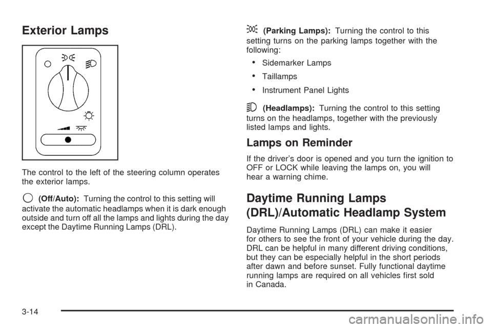
The control to the left of the steering column operates
the exterior lamps.
9(Off/Auto):Turning the control to this setting will
activate the automatic headlamps when it is dark enough
outside and turn off all the lamps and lights during the day
except the Daytime Running Lamps (DRL).
;(Parking Lamps):Turning the control to this
setting turns on the parking lamps together with the
following:
Sidemarker Lamps
Taillamps
Instrument Panel Lights
5(Headlamps):Turning the control to this setting
turns on the headlamps, together with the previously
listed lamps and lights.
Lamps on Reminder
If the driver’s door is opened and you turn the ignition to
OFF or LOCK while leaving the lamps on, you will
hear a warning chime.
Daytime Running Lamps
(DRL)/Automatic Headlamp System
Daytime Running Lamps (DRL) can make it easier
for others to see the front of your vehicle during the day.
DRL can be helpful in many different driving conditions,
but they can be especially helpful in the short periods
after dawn and before sunset. Fully functional daytime
running lamps are required on all vehicles �rst sold
in Canada.
3-14
Page 175 of 470
A light sensor on top of the instrument panel makes the
DRL work, so be sure it is not covered. The DRL
system will make front parking and turn signal lamps
come on in daylight when the following conditions
are met:
The ignition is on.
The exterior lamps control is off.
The parking brake is released.
When the DRL are on, only your front parking and turn
signal lamps will be on. Your instrument panel will
not be lit up.
When it is dark enough outside, the exterior lamps will
come on automatically. When it is bright enough
outside, the exterior lamps will turn off and the DRL will
turn on. Of course, you may still turn on the headlamps
any time you need to.
If you start your vehicle in a dark garage, the automatic
headlamp system will come on immediately. Once
you leave the garage, it will take approximately
one minute for the automatic headlamp system to
change to DRL if it is light outside. During that delay,
your instrument panel cluster may not be as bright
as usual. Make sure your instrument panel brightness
control is in the full bright position. SeeInstrument Panel
Brightness on page 3-15.To idle your vehicle with the DRL and automatic
headlamps off, set the parking brake while the ignition is
in OFF or LOCK. Then start the vehicle. The DRL
and automatic headlamps will stay off until you release
the parking brake.
As with any vehicle, you should turn on the regular
headlamp system when you need it.Instrument Panel Brightness
The thumbwheel for this feature is located below the
exterior lamps control. Turn the thumbwheel to the right
to brighten the lights, or to the left to dim them.
Interior Lamps Control
Turn the thumbwheel all the way to the right to turn on
the interior lamps, if the interior lamps override
switch is off. Turn the thumbwheel to the left to turn the
lamps off.
3-15
Page 176 of 470
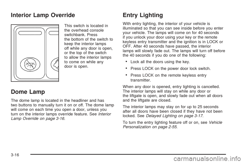
Interior Lamp Override
This switch is located in
the overhead console
switchbank. Press
the bottom of the switch to
keep the interior lamps
off while any door is open,
or the top of the switch
to allow the interior lamps
to come on while any
door is open.
Dome Lamp
The dome lamp is located in the headliner and has
two buttons to manually turn it on or off. The dome lamp
will come on each time you open a door, unless you
turn on the interior lamps override feature. SeeInterior
Lamp Override on page 3-16.
Entry Lighting
With entry lighting, the interior of your vehicle is
illuminated so that you can see inside before you enter
your vehicle. The lamps will come on for 40 seconds
if you unlock your door using your key or the remote
keyless entry transmitter and the ignition is in LOCK or
OFF. After 40 seconds have passed, the interior
lamps will slowly fade out. The lamps will turn off before
the 40 seconds if you do one of the following:
Lock all the doors using the key.
Press LOCK on the power door lock switch.
Press LOCK on the remote keyless entry
transmitter.
When any door is opened, entry lighting is cancelled.
The interior lamps will stay on while any door or
the liftgate is open, and slowly fade out when all doors
and the liftgate are closed.
The interior lamps may stay on for up to 25 seconds
after all doors have been closed if they have not been
locked. SeeDelayed Lighting on page 3-17.
To turn the entry lighting feature off or on, seeVehicle
Personalization on page 2-55.
3-16
Page 177 of 470
Delayed Lighting
The delayed lighting feature will continue to illuminate
the interior for 25 seconds after all doors have been
closed, so that you can �nd your ignition and buckle your
safety belt at night. Delayed lighting will not occur
while the ignition is in RUN or ACCESSORY. After
25 seconds have passed, the interior lamps will slowly
fade out. The lamps will fade out before the 25 seconds
have passed if you do one of the following:
Turn the ignition to RUN or ACCESSORY.
Lock all doors using the remote keyless entry
transmitter.
Lock all doors using the power door lock switch or
the key.
To turn the delayed lighting feature off or on, see
Vehicle Personalization on page 2-55.
Exit Lighting
With exit lighting, the interior lamps will come on for
about 25 seconds whenever you remove the key from
the ignition. If you turn the ignition key to RUN or
ACCESSORY, the lamps will fade out. The lamps will
also fade out if you lock the doors with the power
door lock switch or the remote keyless entry transmitter.
When any door is opened, exit lighting is cancelled.
The interior lamps will stay on while any door or
the liftgate is open, and slowly fade out when all doors
and the liftgate are closed.
The interior lamps may stay on for up to 25 seconds
after all doors have been closed if they have not been
locked. SeeDelayed Lighting on page 3-17.
To turn the exit lighting feature off or on, seeVehicle
Personalization on page 2-55.
3-17