Page 26 of 92
Downloaded from www.Manualslib.com manuals search engine 28
Starting the vehicle using the button
Convenience electrics
326_056 Antenna for
central locking and
anti-theft warning
system
R47
Antenna on driver’s
side for access
start authorisation
R134Antenna on
passenger’s side for
access start
authorisation
R135Passenger
compartment
antenna 1 for access
and start
authorisation
R138
Boot antenna for
access
start authorisation
R137
Switch for access
and start
authorisation
E415
Antenna read-in
unit for keyless access
authorisation
J723 Control unit for access
and start authorisation
J518
Data bus diagnosis
for data bus
J533Engine control unit
J623 Button for access
and start
authorisation
J408
Page 27 of 92

Downloaded from www.Manualslib.com manuals search engine 29
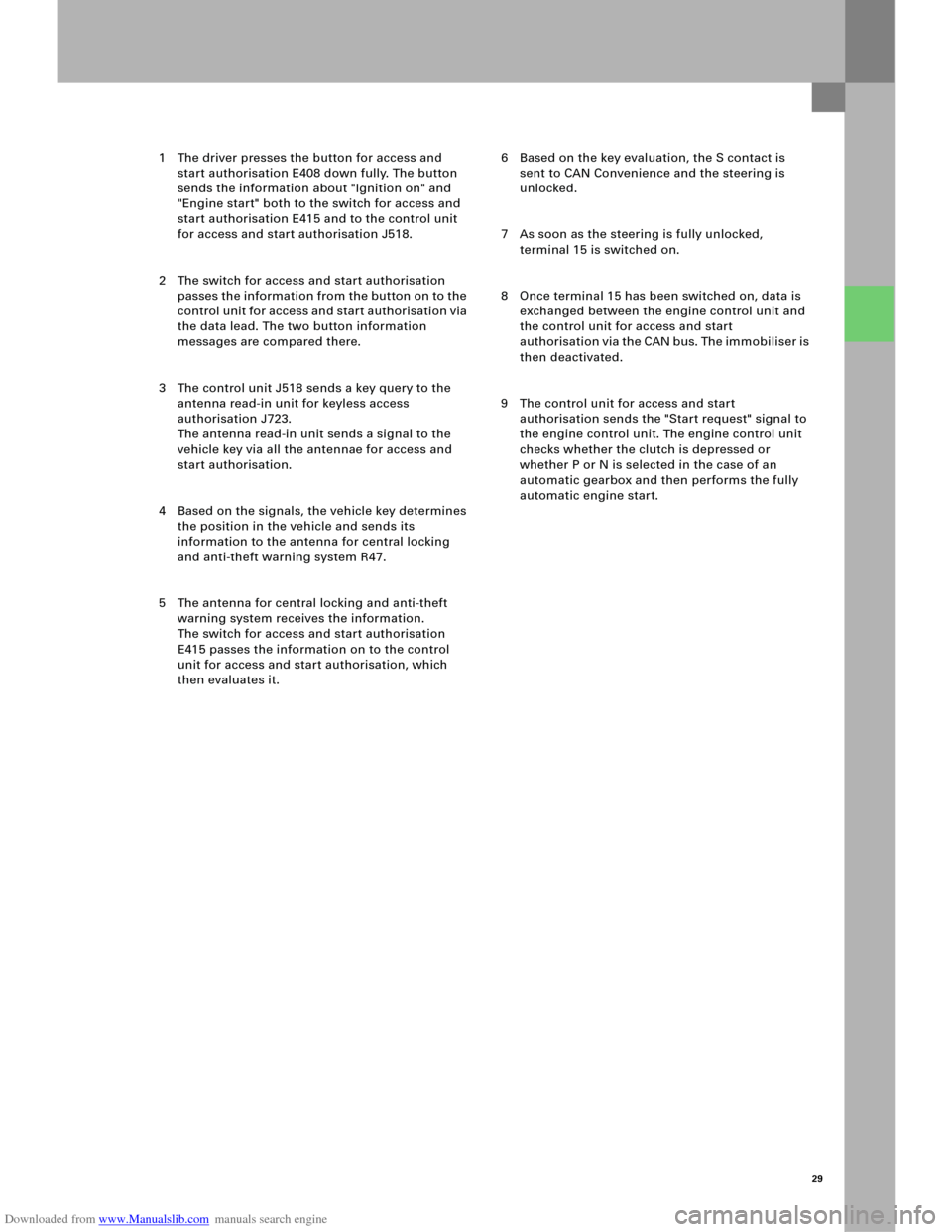
1 The driver presses the button for access and
start authorisation E408 down fully. The button
sends the information about "Ignition on" and
"Engine start" both to the switch for access and
start authorisation E415 and to the control unit
for access and start authorisation J518.
2 The switch for access and start authorisation
passes the information from the button on to the
control unit for access and start authorisation via
the data lead. The two button information
messages are compared there.
3 The control unit J518 sends a key query to the
antenna read-in unit for keyless access
authorisation J723.
The antenna read-in unit sends a signal to the
vehicle key via all the antennae for access and
start authorisation.
4 Based on the signals, the vehicle key determines
the position in the vehicle and sends its
information to the antenna for central locking
and anti-theft warning system R47.
5 The antenna for central locking and anti-theft
warning system receives the information.
The switch for access and start authorisation
E415 passes the information on to the control
unit for access and start authorisation, which
then evaluates it. 6 Based on the key evaluation, the S contact is
sent to CAN Convenience and the steering is
unlocked.
7 As soon as the steering is fully unlocked,
terminal 15 is switched on.
8 Once terminal 15 has been switched on, data is
exchanged between the engine control unit and
the control unit for access and start
authorisation via the CAN bus. The immobiliser is
then deactivated.
9 The control unit for access and start
authorisation sends the "Start request" signal to
the engine control unit. The engine control unit
checks whether the clutch is depressed or
whether P or N is selected in the case of an
automatic gearbox and then performs the fully
automatic engine start.
Page 28 of 92
Downloaded from www.Manualslib.com manuals search engine 30
Immobiliser 4
Convenience electrics
The immobiliser 4 technology is used in the
Audi A6 ’05.
This means that all components must be "taught"
online, as is already the case with the Audi A8 ´03
and the Audi A3 ´04.
The following components are integrated into the
immobiliser:
– The control unit for access and
start authorisation
– The engine control unit
– The vehicle keysControl unit, which is not integrated into the
immobiliser
Control unit, which is integrated into the
immobiliser
Master control unit
PC/mainframe
326_099
Immobiliser and component protection
E415 J518
J533 J623
Page 33 of 92

Downloaded from www.Manualslib.com manuals search engine 35
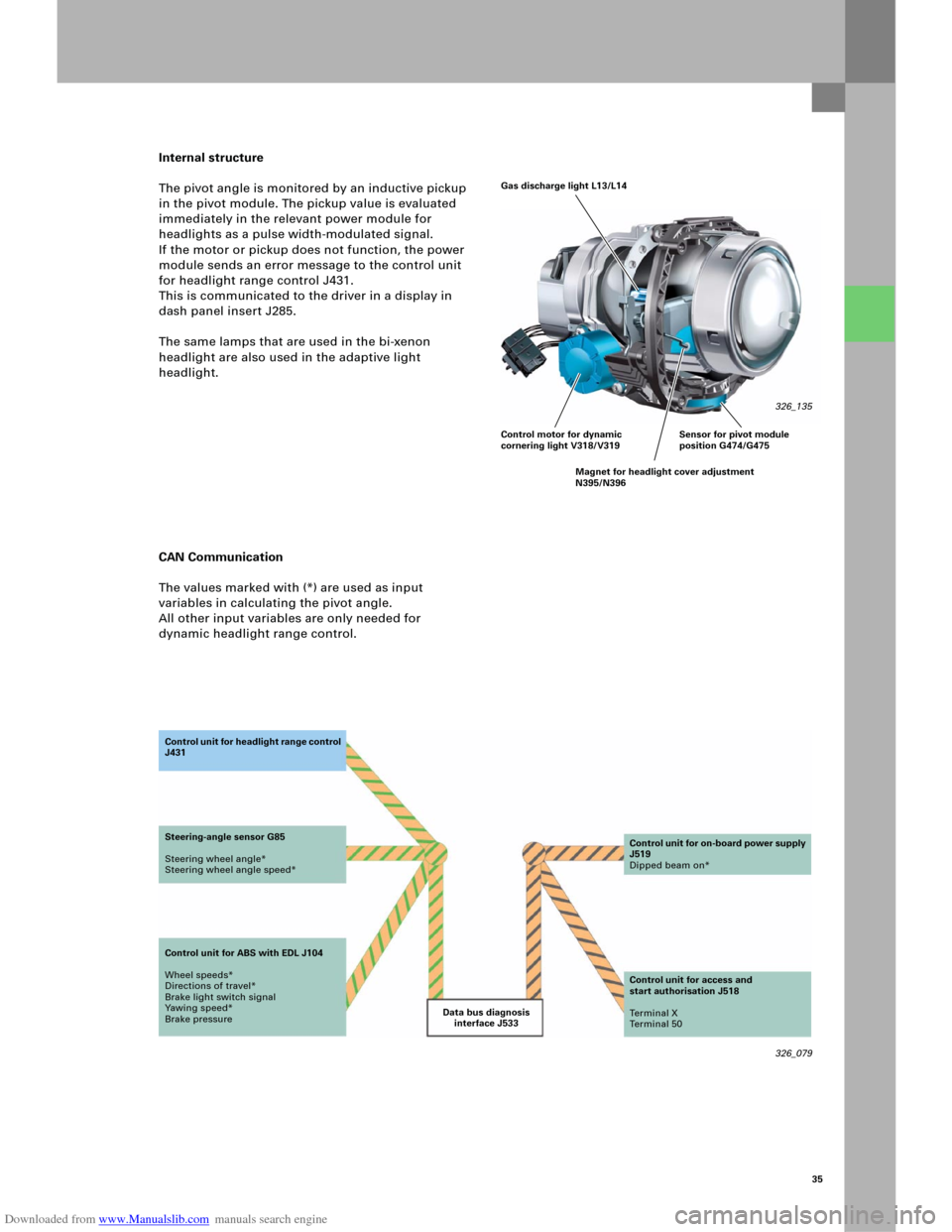
Internal structure
The pivot angle is monitored by an inductive pickup
in the pivot module. The pickup value is evaluated
immediately in the relevant power module for
headlights as a pulse width-modulated signal.
If the motor or pickup does not function, the power
module sends an error message to the control unit
for headlight range control J431.
This is communicated to the driver in a display in
dash panel insert J285.
The same lamps that are used in the bi-xenon
headlight are also used in the adaptive light
headlight.
CAN Communication
The values marked with (*) are used as input
variables in calculating the pivot angle.
All other input variables are only needed for
dynamic headlight range control.
326_079 Data bus diagnosis
interface J533 Co n t ro l u n it fo r h e a d li g h t ra n g e c o n t ro l
J431
Steering-angle sensor G85
Steering wheel angle*
Steering wheel angle speed*
Control unit for ABS with EDL J104
Wheel speeds*
Directions of travel*
Brake light switch signal
Yawing speed*
Brake pressureControl unit for on-board power supply
J519
Dipped beam on*
Control unit for access and
start authorisation J518
Te r m i n a l X
Te r m i n a l 5 0
Gas discharge light L13/L14
326_135
Control motor for dynamic
cornering light V318/V319
Magnet for headlight cover adjustment
N395/N396Sensor for pivot module
position G474/G475
Page 60 of 92

Downloaded from www.Manualslib.com manuals search engine 62
326_119
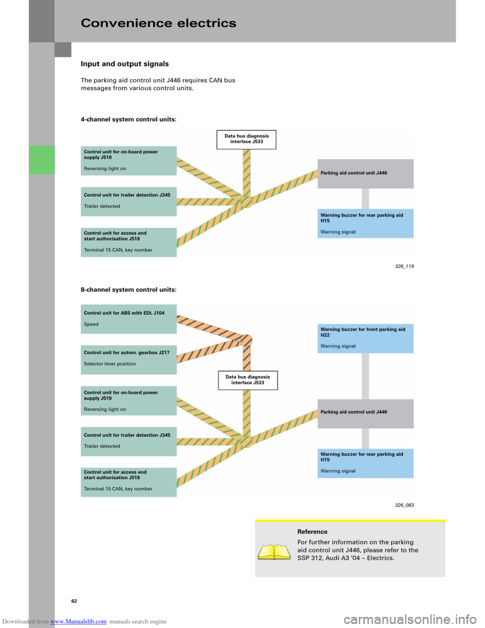
Input and output signals
The parking aid control unit J446 requires CAN bus
messages from various control units.
4-channel system control units:
Convenience electrics
Control unit for on-board power
supply J519
Reversing light on
Control unit for trailer detection J345
Tr a i l e r d e t e c t e dData bus diagnosis
interface J533
Parking aid control unit J446
Warning buzzer for rear parking aid
H15
Warning signal
Control unit for access and
start authorisation J518
Terminal 15 CAN, key number
Control unit for ABS with EDL J104
Speed
Control unit for autom. gearbox J217
Selector lever position
Control unit for on-board power
supply J519
Reversing light on
Control unit for trailer detection J345
Tr a i l e r d e t e c t e dData bus diagnosis
interface J533Warning buzzer for front parking aid
H22
Warning signal
Parking aid control unit J446
Warning buzzer for rear parking aid
H15
Warning signal
326_083 Control unit for access and
start authorisation J518
Terminal 15 CAN, key number
Reference
For further information on the parking
aid control unit J446, please refer to the
SSP 312, Audi A3 ’04 – Electrics.
8-channel system control units: