Page 9 of 92
Downloaded from www.Manualslib.com manuals search engine 9
326_148
Page 10 of 92
Downloaded from www.Manualslib.com manuals search engine 10
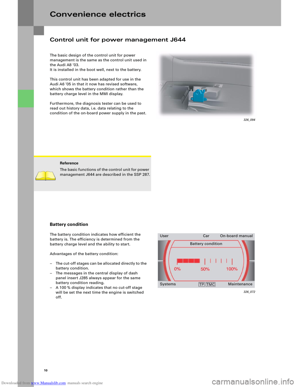
The basic design of the control unit for power
management is the same as the control unit used in
the Audi A8 ‘03.
It is installed in the boot well, next to the battery.
This control unit has been adapted for use in the
Audi A6 ’05 in that it now has revised software,
which shows the battery condition rather than the
battery charge level in the MMI display.
Furthermore, the diagnosis tester can be used to
read out history data, i.e. data relating to the
condition of the on-board power supply in the past.
Convenience electrics
Reference
The basic functions of the control unit for power
management J644 are described in the SSP 287.
Battery condition
The battery condition indicates how efficient the
battery is. The efficiency is determined from the
battery charge level and the ability to start.
Advantages of the battery condition:
– The cut-off stages can be allocated directly to the
battery condition.
– The messages in the central display of dash
panel insert J285 always appear for the same
battery condition reading.
– A 100 % display indicates that no cut-off stage
will be set the next time the engine is switched
off.
326_072
User Car On-board manual
Battery condition
Systems Maintenance
Control unit for power management J644
326_094
Page 11 of 92
Downloaded from www.Manualslib.com manuals search engine Audi
Audi A6 2005>
2005 (5)
Saloon
BBJ 3.0l Motronic / 160 kW Guided fault-finding
Function/component selection
Selecting a function or component
Electrical system (Rep. Gr. 01; 90 - 97)
01 – Self-diagnosis systems
61 – Battery control
J644 – Control unit for power management, Functions
A – Battery, Charge level
A – Battery, Battery testing
J644 – Power management, General description
J644 – Control unit for power management, Coding
J644 – Read out history data
J644 – Power management, Read measured-value blocks
J644 – Power management, Query fault memory
J644 – Data link tests for generator voltage
J644 – Replace control unit
J644 – Power management, Activate/deactivate Transport mode
Battery change history
Data for the last three battery changes is stored.
Power balance history – driving (= engine on)
The power balance and duration of the last five
journeys are logged.
Power balance history – idle (= engine off)
The power balance and duration of the last five idle
times are logged.
Other data is not relevant for Customer Service.
History dataThe diagnosis tester can be used to read out
data from the control unit for power management,
which makes it much easier to analyse the on-board
power supply and the battery.
Open-circuit voltage history
If the battery open-circuit voltage is less than the
threshold values of 12.5 volts, 12.2 volts and
11.5 volts, an entry is written to the history data.
The last four entries can always be read out.
Voltage measurement starts when
– CAN Convenience is in Sleep mode and
– terminal 15 is switched off for at least 2 hours
and
– the vehicle’s power consumption is < 100 mA.
Voltage measurement ends when
– the voltage increases or
– the current increases or
– the control unit triggers Sleep mode or
– the control unit detects a new battery.
Closed-circuit current history
If the closed-circuit current exceeds the threshold
value of 50 mA, an entry is written to the history
data. The last ten entries can be read out.
Current measurement starts when
– CAN Convenience is in Sleep mode and
– terminal 15 is switched off for at least 2 hours
and
– the vehicle’s power consumption is > 50 mA.
Current measurement ends when
– the current decreases or
– the control unit triggers Sleep mode.
Breakdown analysis
If the control unit for power management detects
the status "Cannot start vehicle", an entry is written
to the history data.
Cut-off level history
Data for the last 15 cut-off levels is stored.
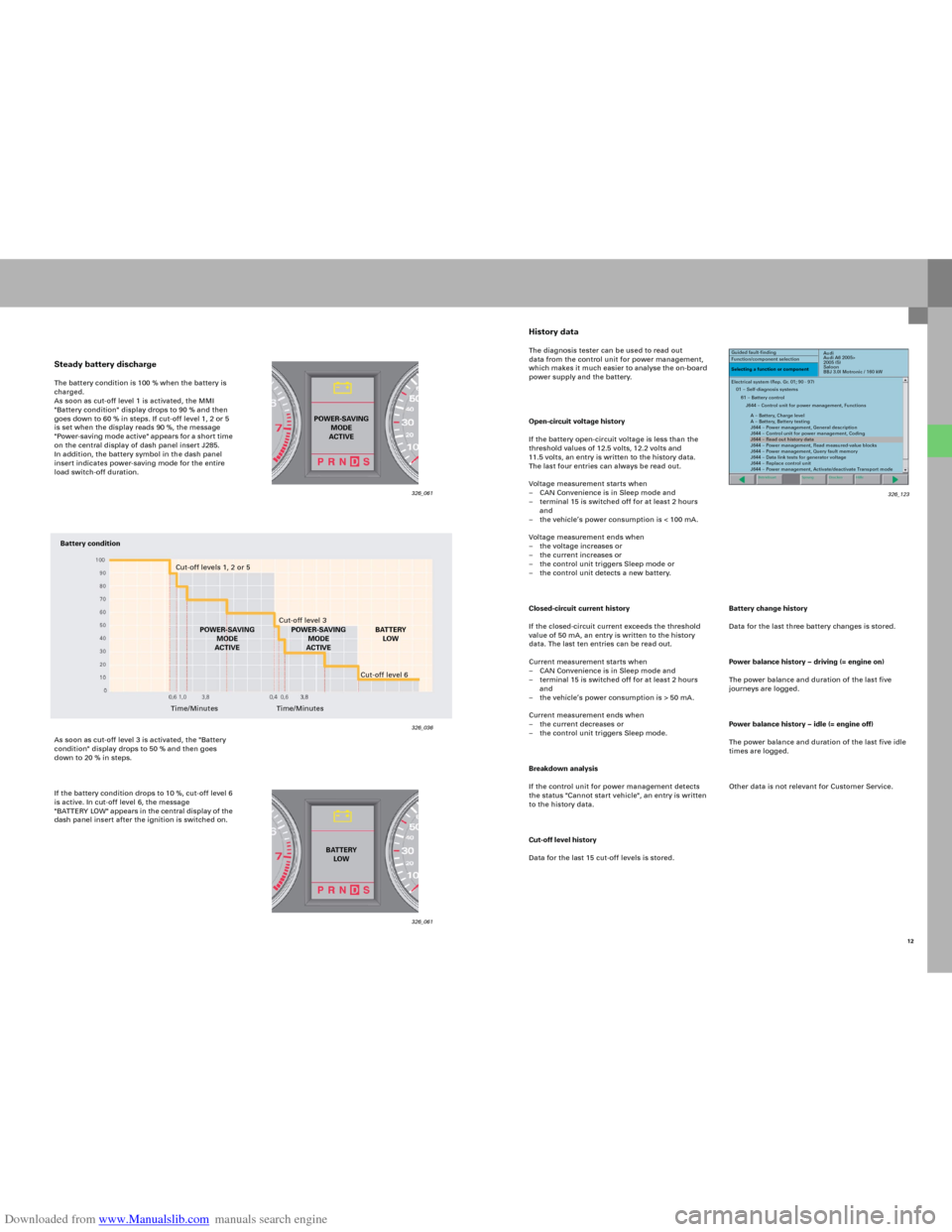
Steady battery dischargeThe battery condition is 100 % when the battery is
charged.
As soon as cut-off level 1 is activated, the MMI
"Battery condition" display drops to 90 % and then
goes down to 60 % in steps. If cut-off level 1, 2 or 5
is set when the display reads 90 %, the message
"Power-saving mode active" app ears fo r a sho r t time
on the central display of dash panel insert J285.
In addition, the battery symbol in the dash panel
insert indicates power-saving mode for the entire
load switch-off duration.
As soon as cut-off level 3 is activated, the "Battery
condition" display drops to 50 % and then goes
down to 20 % in steps.
If the battery condition drops to 10 %, cut-off level 6
is active. In cut-off level 6, the message
"B AT TERY LOW" appears in the central di splay of the
dash panel insert after the ignition is switched on.
326_061 326_061
326_036
POWER-SAVING
MODE
ACTIVE
BATTERY
LOW
Battery condition
Cut-off levels 1, 2 or 5
Cut-off level 3
POWER-SAVING
MODE
ACTIVEBATTERY
LOW
Time/MinutesCut-off level 6
Time/MinutesPOWER-SAVING
MODE
ACTIVE
12 326_123
Page 12 of 92
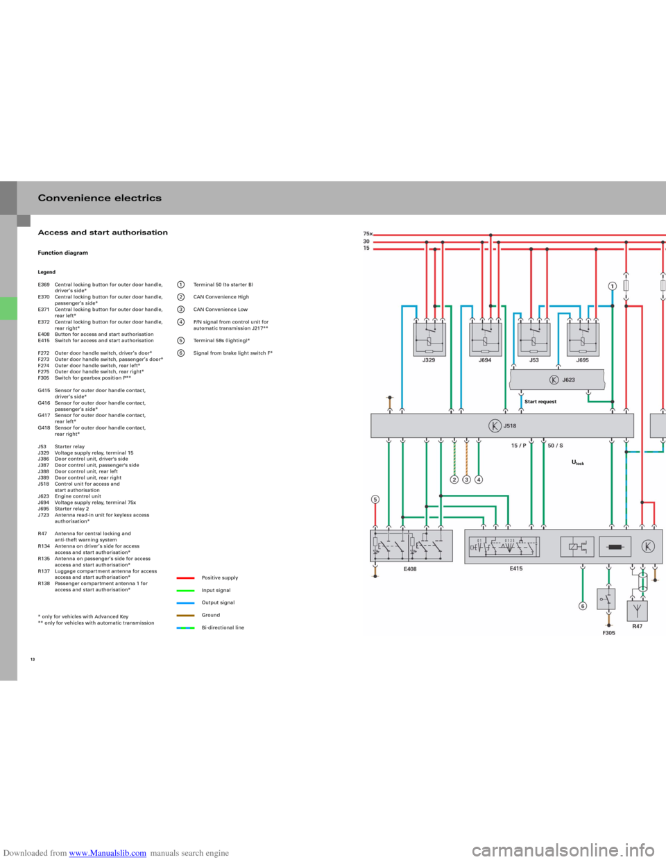
Downloaded from www.Manualslib.com manuals search engine Convenience electricsFunction diagramLegend
E369 Central locking button for outer door handle,
driver’s side*
E370 Central locking button for outer door handle,
passenger’s side*
E371 Central locking button for outer door handle,
rear left*
E372 Central locking button for outer door handle,
rear right*
E408 Button for access and start authorisation
E415 Switch for access and start authorisation
F272 Outer door handle switch, driver’s door*
F273 Outer door handle switch, passenger’s door*
F274 Outer door handle switch, rear left*
F275 Outer door handle switch, rear right*
F305 Switch for gearbox position P**
G415 Sensor for outer door handle contact,
driver’s side*
G416 Sensor for outer door handle contact,
passenger’s side*
G417 Sensor for outer door handle contact,
rear left*
G418 Sensor for outer door handle contact,
rear right*
J53 Starter relay
J329 Voltage supply relay, terminal 15
J386 Door control unit, driver's side
J387 Door control unit, passenger's side
J388 Door control unit, rear left
J389 Door control unit, rear right
J518 Control unit for access and
start authorisation
J623 Engine control unit
J694 Voltage supply relay, terminal 75x
J695 Starter relay 2
J723 Antenna read-in unit for keyless access
authorisation*
R47 Antenna for central locking and
anti-theft warning system
R134 Antenna on driver’s side for access
access and start authorisation*
R135 Antenna on passenger’s side for access
access and start authorisation*
R137 Luggage compartment antenna for access
access and start authorisation*
R138 Passenger compartment antenna 1 for
access and start authorisation*
* only for vehicles with Advanced Key
** only for vehicles with automatic transmission
1 Terminal 50 (to starter B)
2 CAN Convenience High
3 CAN Convenience Low
4 P/N signal from control unit for
automatic transmission J217**
5 Terminal 58s (lighting)*
6 Signal from brake light switch F*
Positive supply
Input signal
Output signal
Ground
Bi-directional line
13
Access and start authorisation
Start request
Ulock
Page 13 of 92
Downloaded from www.Manualslib.com manuals search engine 15
326_038
Page 14 of 92
Downloaded from www.Manualslib.com manuals search engine 16
The Advanced Key system was introduced with the
Audi A8 '03 and has been fundamentally revised for
the Audi A6 ’05.
The most important new feature is that the control
unit for access and start authorisation has been
combined with the actuator for steering column
locking.
Convenience electrics
System overview
Page 15 of 92
Downloaded from www.Manualslib.com manuals search engine 17
326_147
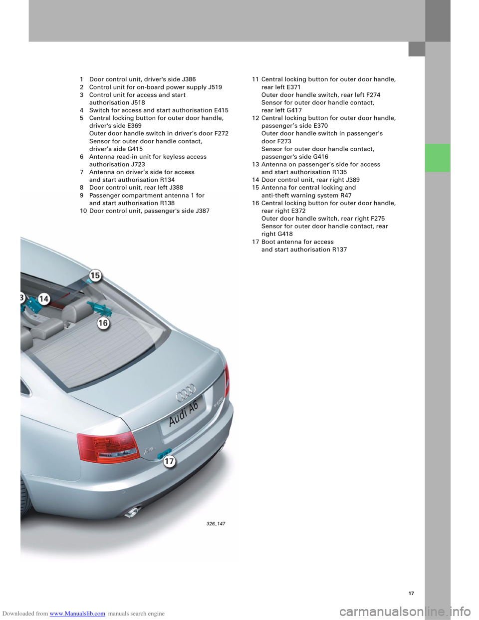
1 Door control unit, driver's side J386
2 Control unit for on-board power supply J519
3 Control unit for access and start
authorisation J518
4 Switch for access and start authorisation E415
5 Central locking button for outer door handle,
driver's side E369
Outer door handle switch in driver’s door F272
Sensor for outer door handle contact,
driver’s side G415
6 Antenna read-in unit for keyless access
authorisation J723
7 Antenna on driver’s side for access
and start authorisation R134
8 Door control unit, rear left J388
9 Passenger compartment antenna 1 for
and start authorisation R138
10 Door control unit, passenger's side J38711 Central locking button for outer door handle,
rear left E371
Outer door handle switch, rear left F274
Sensor for outer door handle contact,
rear left G417
12 Central locking button for outer door handle,
passenger’s side E370
Outer door handle switch in passenger’s
door F273
Sensor for outer door handle contact,
passenger's side G416
13 Antenna on passenger’s side for access
and start authorisation R135
14 Door control unit, rear right J389
15 Antenna for central locking and
anti-theft warning system R47
16 Central locking button for outer door handle,
rear right E372
Outer door handle switch, rear right F275
Sensor for outer door handle contact, rear
right G418
17 Boot antenna for access
and start authorisation R137
Page 16 of 92
Downloaded from www.Manualslib.com manuals search engine 18
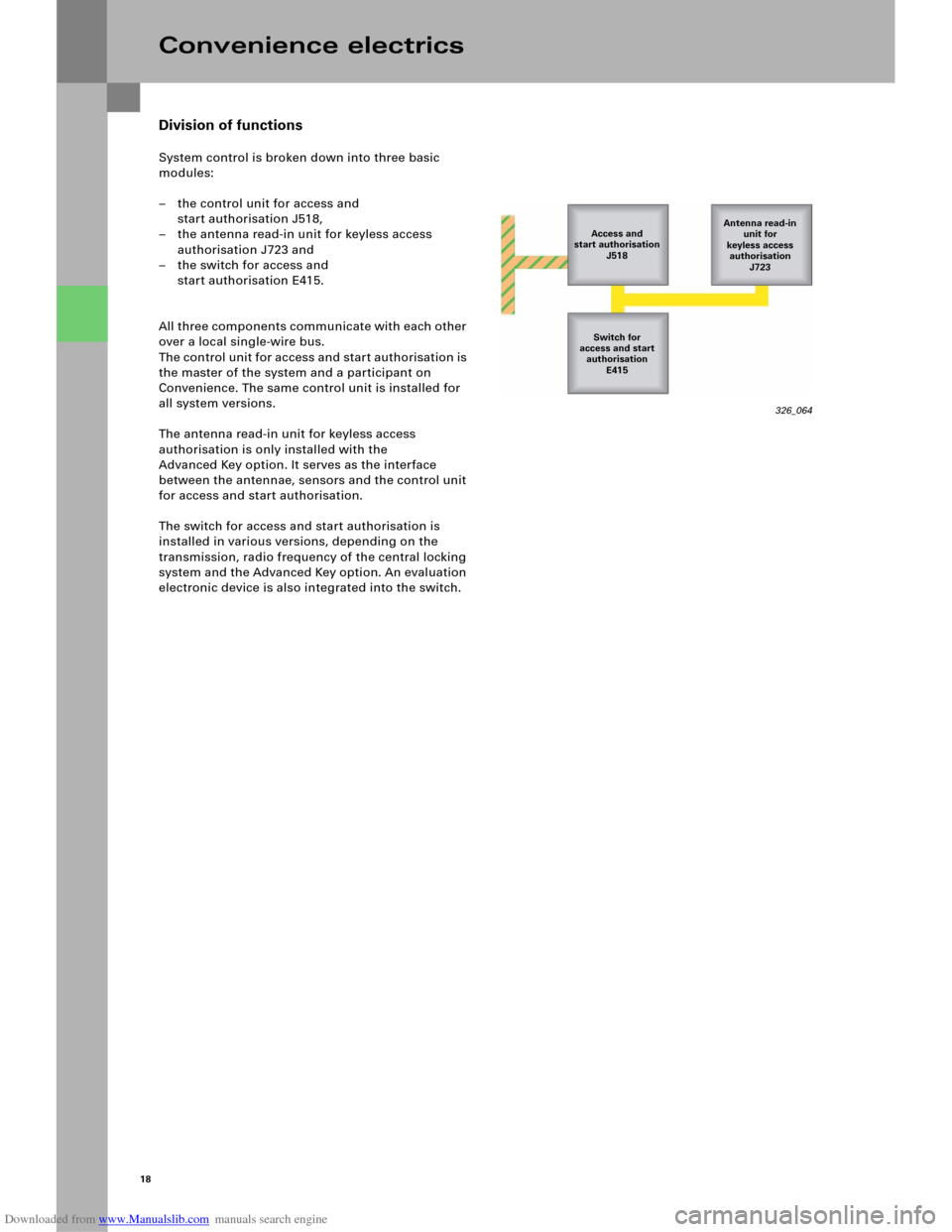
Division of functions
System control is broken down into three basic
modules:
– the control unit for access and
start authorisation J518,
– the antenna read-in unit for keyless access
authorisation J723 and
– the switch for access and
start authorisation E415.
All three components communicate with each other
over a local single-wire bus.
The control unit for access and start authorisation is
the master of the system and a participant on
Convenience. The same control unit is installed for
all system versions.
The antenna read-in unit for keyless access
authorisation is only installed with the
Advanced Key option. It serves as the interface
between the antennae, sensors and the control unit
for access and start authorisation.
The switch for access and start authorisation is
installed in various versions, depending on the
transmission, radio frequency of the central locking
system and the Advanced Key option. An evaluation
electronic device is also integrated into the switch.
Convenience electrics
326_064
Access and
start authorisation
J518Antenna read-in
unit for
keyless access
authorisation
J723
Switch for
access and start
authorisation
E415