Page 39 of 92
Downloaded from www.Manualslib.com manuals search engine 41
Function diagram
Legend
E493 Operating button for dash panel insert
F1 Oil pressure switch
F34 Warning contact for brake fluid level
E66 Switch for low coolant display
F77 Warning contact for windscreen washer level
G Sender for fuel level indicator
G6 Pre-feed fuel pump
G17 Temperature sensor for outside temperature
G34 Sensor for brake pad wear, front left
G35 Sensor for brake pad wear, front right
G169 Fuel level sensor 2*
G266 Oil level and oil temperature sensor
J17 Fuel pump relay
J285 Control unit in dash panel insert
J489 Receiver for radio clock
J533 Data bus diagnosis interface
J540 Control unit for electric parking and
hand brake
* only for vehicles with quattro drive
326_037
Additional signal
1 Terminal 58d
2 Terminal 58s
Page 54 of 92

Downloaded from www.Manualslib.com manuals search engine 56
326_121
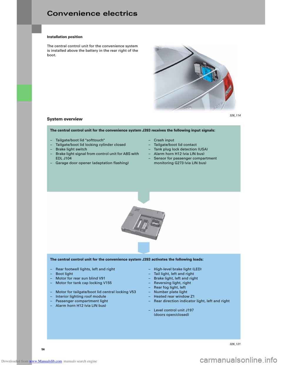
Installation position
The central control unit for the convenience system
is installed above the battery in the rear right of the
boot.
System overview
Convenience electrics
– Tailgate/boot lid "softtouch"
– Tailgate/boot lid locking cylinder closed
– Brake light switch
– B rake li ght signal from control u ni t fo r ABS with
EDL J104
– Garage door opener (adaptation flashing)– Crash input
– Tailgate/boot lid contact
–Tank plug lock detection (USA)
– Alarm horn H12 (via LIN bus)
– Sensor for passenger compartment
monitoring G273 (via LIN bus)
– Rear footwell lights, left and right
– Boot light
– Motor for rear sun blind V91
– Motor for tank cap locking V155
– Motor for tailgate/boot lid central locking V53
– Interior lighting roof module
– Passenger compartment light
– Alarm horn H12 (via LIN bus)– High-level brake light (LED)
– Tail light, left and right
–Brake light, left and right
– Reversing light, right
–Rear fog light, left
– Number plate light
– Heated rear window Z1
– Rear direction indicator light, left and right
– Level control unit J197
(doors open/closed) The central control unit for the convenience system J393 receives the following input signals:
The central control unit for the convenience system J393 activates the following loads:
326_114
Page 56 of 92

Downloaded from www.Manualslib.com manuals search engine 58
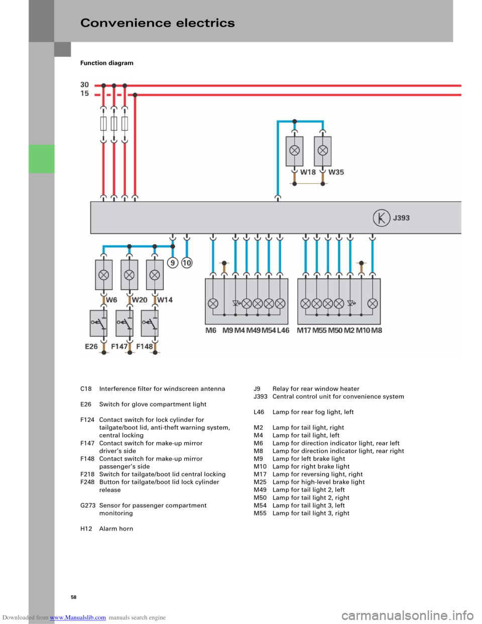
Function diagram
Convenience electrics
C18 Interference filter for windscreen antenna
E26 Switch for glove compartment light
F124 Contact switch for lock cylinder for
tailgate/boot lid, anti-theft warning system,
central locking
F147 Contact switch for make-up mirror
driver’s side
F148 Contact switch for make-up mirror
passenger’s side
F218 Switch for tailgate/boot lid central locking
F248 Button for tailgate/boot lid lock cylinder
release
G273 Sensor for passenger compartment
monitoring
H12 Alarm hornJ9 Relay for rear window heater
J393 Central control unit for convenience system
L46 Lamp for rear fog light, left
M2 Lamp for tail light, right
M4 Lamp for tail light, left
M6 Lamp for direction indicator light, rear left
M8 Lamp for direction indicator light, rear right
M9 Lamp for left brake light
M10 Lamp for right brake light
M17 Lamp for reversing light, right
M25 Lamp for high-level brake light
M49 Lamp for tail light 2, left
M50 Lamp for tail light 2, right
M54 Lamp for tail light 3, left
M55 Lamp for tail light 3, right
Page 57 of 92
Downloaded from www.Manualslib.com manuals search engine 59
326_120
V53 Motor for tailgate/boot lid central locking
V91 Motor for rear sun blind
V155 Motor for tank cap locking
W6 Glove compartment light
W14 Illuminated make-up mirror, passenger’s side
W18 Boot light, left
W20 Illuminated make-up mirror, driver’s side
W35 Boot light, right
W45 Footwell light, rear left
W46 Footwell light, rear right
X Number plate light
Z1 Heated rear window Additional signals
1CAN Convenience High
2CAN Convenience Low
3 Brake light switch F
4 ESP brake signal from control unit for ABS
with EDL J104
5 Crash signal from airbag control unit J234
6 "Doors OPEN" signal to level control unit J197
7 "Adaptation flashing" signal from control unit
for garage door opening J530
8 "Release" signal to motor for sliding roof V1
9 + 10 "Interior light" activation signal
to roof module W1
Page 58 of 92

Downloaded from www.Manualslib.com manuals search engine 60
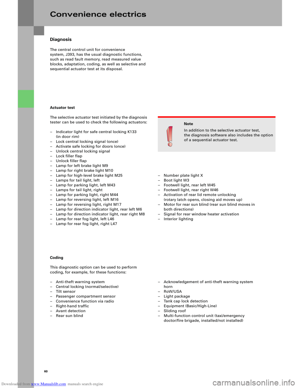
Diagnosis
The central control unit for convenience
system, J393, has the usual diagnostic functions,
such as read fault memory, read measured value
blocks, adaptation, coding, as well as selective and
sequential actuator test at its disposal.
Actuator test
The selective actuator test initiated by the diagnosis
tester can be used to check the following actuators:
– Indicator light for safe central locking K133
(in door rim)
– Lock central locking signal (once)
– Activate safe locking for doors (once)
– Unlock central locking signal
– Lock filler flap
– Unlock filler flap
– Lamp for left brake light M9
– Lamp for right brake light M10
– Lamp for high-level brake light M25
– Lamps for tail light, left
– Lamp for parking light, left M43
– Lamps for tail light, right
– Lamp for parking light, right M44
– Lamp for reversing light, left M16
– Lamp for reversing light, right M17
– Lamp for direction indicator light, rear left M6
– Lamp for direction indicator light, rear right M8
– Lamp for rear fog light, left L46
– Lamp for rear fog light, right L47
Coding
This diagnostic option can be used to perform
coding, for example, for these functions:
– Anti-theft warning system
– Central locking (normal/selective)
–Tilt sensor
– Passenger compartment sensor
– Convenience function via radio
–Right-hand traffic
–Avant detection
–Rear sun blind
Convenience electrics
Note
In addition to the selective actuator test,
the diagnosis software also includes the option
of a sequential actuator test.
– Number plate light X
– Boot light W3
– Footwell light, rear left W45
– Footwell light, rear right W46
– Activation of rear lid remote unlocking
(rotary latch opens, closing aid moves up)
– Motor for rear sun blind (rear sun blind moves in
both directions)
– Signal for rear window heater activation
–Interior lighting
– Acknowledgement of anti-theft warning system
horn
–RoW/USA
–Light package
– Tank cap lock detection
– Equipment (Basic/High-Line)
–Sliding roof
– Multi-function control unit (taxi/emergency
doctor/fire brigade, installed/not installed)
Page 73 of 92

Downloaded from www.Manualslib.com manuals search engine 75
Antenna systems
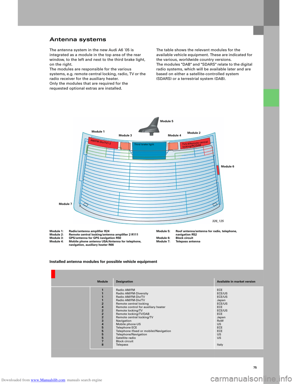
The antenna system in the new Audi A6 ´05 is
integrated as a module in the top area of the rear
window, to the left and next to the third brake light,
on the right.
The modules are responsible for the various
s y s t e m s, e . g . re m o t e c e n t ral lo ck i n g , rad i o , T V o r t h e
radio receiver for the auxiliary heater.
Only the modules that are required for the
requested optional extras are installed.The table shows the relevant modules for the
available vehicle equipment. These are indicated for
the various, worldwide country versions.
The modules "DAB" and "SDARS" relate to the digital
radio systems, which will be available later and are
based on either a satellite-controlled system
(SDARS) or a terrestrial system (DAB).
ModuleDesignationAvailable in market version
1
1
1
1
2
4
2
2
2
3
4
5
5
5
5
7
8Radio AM/FM
Radio AM/FM-Diversity
Radio AM/FM-Div/TV
Radio AM/FM-Div/TV
Remote central locking
Remote control for auxiliary heater
Remote locking/TV
Remote locking/TV/DAB
Remote central locking/TV
Navigation
Mobile phone-US
Te l e p h o n e E C E
Telephone (fixed or mobile)/Navigation
Telephone/Navigation
Satellite radio
Block circuit
Te l e p a s sECE
ECE/US
ECE/US
Japan
ECE/US
ECE
ECE/US
ECE
Japan
RoW
US
ECE
ECE
US
US
Italy
Installed antenna modules for possible vehicle equipment
Module 1
Module 3 Module 4Module 2 Module 5
Module 7Module 6
A
M
/F
M
-Di
v/
TV
1-2Third brake lightT
V3-
4
/R
emot
e
c
ent
ra
l
locking/R
C
/DA
B
326_125
Module 1: Radio/antenna amplifier R24
Module 2: Remote central locking/antenna amplifier 2 R111
Module 3: GPS/antenna for GPS navigation R50
Module 4: Mobile phone antenna USA/Antenna for telephone,
navigation, auxiliary heater R66Module 5: Roof antenna/antenna for radio, telephone,
navigation R52
Module 6: Block circuit
Module 7: Telepass antenna
Page 91 of 92
Downloaded from www.Manualslib.com manuals search engine SSP 324 Audi A6 ´05 Chassis
– Front axle technology
– Rear axle technology
– Steering system
–ESP
– Electromechanical parking brake EPB
Order No.: A04.5S00.07.00
SSP 326 Audi A6 ´05 Electrics
–Networking
– Bus topologies
– Convenience electrics
– Infotainment
Order No.: A04.5S00.09.00 SSP 323 Audi A6 ´05
– Introduction to the vehicle
–Body technology
– Passenger protection
– Air conditioning
Order No.: A04.5S00.06.00
SSP 325 Audi A6 ´05 Engines and Gears
– 3.0 V6 TDI Common Rail
–3.2 V6 FSI
– Manual gearbox 01X, 02X, 0A3
– 6-stage automatic transmission 09L
– Multitronic 01J
Order No.: A04.5S00.08.00
Self-study programmes for the Audi A6 ‘05
323_057
323_058
323_059
323_056