Page 221 of 457

4-74
SWINGARM AND DRIVE CHAINCHAS
CAUTION:
2. Check:
�drive chain
Stiffness � Clean and lubricate or replace.
3. Clean:
�drive chain
a. Wipe the drive chain with a clean cloth.
b. Put the drive chain in kerosene and remove
any remaining dirt.
c. Remove the drive chain from the kerosene
and completely dry it.
This motorcycle has a drive chain with small
rubber O-rings
1 between the drive chain
side plates. Never use high-pressure water
or air, steam, gasoline, certain solvents
(e.g., benzine), or a coarse brush to clean the
drive chain. High-pressure methods could
force dirt or water into the drive chain’s in-
ternals, and solvents will deteriorate the O-
rings. A coarse brush can also damage the
O-rings. Therefore, use only kerosene to
clean the drive chain. Don’t soak drive chain
in kerosine more them ten minutes. O-ring is
damage by kerosine.
4. Check:
�O-rings
1
Damage � Replace the drive chain.
�drive chain rollers
2
Damage / wear � Replace the drive chain.
�drive chain side plates
3
Damage / wear � Replace the drive chain.
Cracks � Replace the drive chain and make
sure the battery breather hose is properly
routed away from the drive chain and below
the swingarm.
5. Lubricate:
�drive chain
Recommended lubricant
Engine oil or chain lubricant
suitable for O-ring chains
ProCarManuals.com
Page 240 of 457
5-18
CAMSHAFTENG
NOTE:
NOTE:
NOTE:
3. Install:
�timing chain tensioner spring
�timing chain tension rod
1
Prior to installing the timing chain tensioner rod,
drain the engine oil from the timing chain ten-
sioner housing.
a. Install the timing chain tensioner spring and
timing chain tensioner rod
1.
b. Squeeze the timing chain tensioner clip
2
and push the timing chain tensioner rod 3.
When the timing chain tensioner rod
3 is
pushed while holding the grip of the timing chain
tensioner clip
2, make sure not to release the
timing chain tensioner rod
3 before releasing
the timing chain tensioner clip
2. (Otherwise,
the timing chain tensioner rod
3 may run off.)
c. Hook the clip
4 to the timing chain tensioner
rod
3.
Hook the timing chain tensioner rod pin
5 to the
center of the clip
4. After the installation, check
that the clip
4 can come off by its own weight by
pushing the timing chain tensioner rod
3 at the
position of installation.
ProCarManuals.com
Page 243 of 457
5-21
CAMSHAFTENG
10 Nm (1.0 m�kg, 7.2 ft�lb)
CAUTION:
WARNING
8. Install:
�O-ring
New
�timing chain tensioner
1
�timing chain tensioner bolts 2
The “arrow” mark a on the timing chain ten-
sioner should face up.
Always use a new O-ring.
9. Turn:
�crankshaft
(several full turns clockwise)
10. Check:
�“T” mark
a
Make sure the “T” mark on the pickup rotor is
aligned with the crankcase mating sure face
b.
�camshaft punch mark
c
Make sure the punch mark c on the cam-
shaft is aligned with the camshaft cap arrow
mark
d.
Out of alignment � Adjust.
Refer to the installation steps above.
11. Measure:
�valve clearance
Out of specification � Adjust.
Refer to “ADJUSTING THE VALVE CLEAR-
ANCE” in chapter 3.
12. Install:
�pickup coil rotor cover
Refer to “CRANKSHAFT POSITION SEN-
SOR”.
ProCarManuals.com
Page 246 of 457
5-24
CYLINDER HEADENG
8 Nm (0.8 m�kg, 5.8 ft�lb)
NOTE:
NOTE:
19 Nm (1.9 m�kg, 14 ft�lb)
67 Nm (6.7 m�kg, 48 ft�lb)
12 Nm (1.2 m�kg, 8.7 ft�lb)
NOTE:
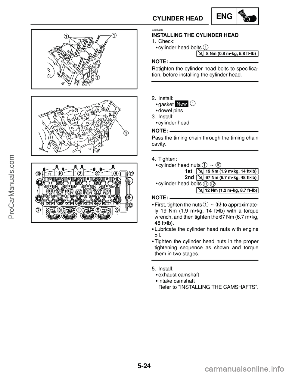
EAS00233
INSTALLING THE CYLINDER HEAD
1. Check:
�cylinder head bolts
1
Retighten the cylinder head bolts to specifica-
tion, before installing the cylinder head.
2. Install:
�gasket
New
1
�dowel pins
3. Install:
�cylinder head
Pass the timing chain through the timing chain
cavity.
4. Tighten:
�cylinder head nuts
1 � 10
1st
2nd
�cylinder head bolts
11 12
�First, tighten the nuts 1 � 10 to approximate-
ly 19 Nm (1.9 m�kg, 14 ft�lb) with a torque
wrench, and then tighten the 67 Nm (6.7 m�kg,
48 ft�lb).
�Lubricate the cylinder head nuts with engine
oil.
�Tighten the cylinder head nuts in the proper
tightening sequence as shown and torque
them in two stages.
5. Install:
�exhaust camshaft
�intake camshaft
Refer to “INSTALLING THE CAMSHAFTS”.
ProCarManuals.com
Page 251 of 457

90890-04111
Exhaust (4.5 mm, 0.18 in)
90890-04116, YM-")
5-29
VALVES AND VALVE SPRINGSENG
NOTE:
NOTE:
After replacing the valve guide, reface the valve
seat.
Valve guide remover
Intake (4.0 mm, 0.16 in)
90890-04111
Exhaust (4.5 mm, 0.18 in)
90890-04116, YM-4116
Valve guide installer
Intake (4.0 mm, 0.16 in)
90890-04112
Exhaust (4.5 mm, 0.18 in)
90890-04117, YM-4117
Valve guide reamer
Intake (4.0 mm, 0.16 in)
90890-04113
Exhaust (4.5 mm, 0.18 in)
90890-04118, YM-4118
3. Eliminate:
�carbon deposits
(from the valve face and valve seat)
4. Check:
�valve face
Pitting / wear � Grind the valve face.
�valve stem end
Mushroom shape or diameter larger than the
body of the valve stem � Replace the valve.
5. Measure:
�valve margin thickness
a
Out of specification � Replace the valve.
Valve margin thickness
0.5 � 0.9 mm
(0.0197 � 0.0354 in)
: 0.5 mm (0.02 in)
6. Measure:
�valve stem runout
Out of specification � Replace the valve.
�When installing a new valve, always replace
the valve guide.
�If the valve is removed or replaced, always re-
place the oil seal.
Valve stem runout
0.01 mm (0.0004 in)
ProCarManuals.com
Page 253 of 457

5-31
VALVES AND VALVE SPRINGSENG
CAUTION:
NOTE:
a. Apply a coarse lapping compound a to the
valve face.
Do not let the lapping compound enter the
gap between the valve stem and the valve
guide.
b. Apply molybdenum disulfide oil onto the
valve stem.
c. Install the valve into the cylinder head.
d. Turn the valve until the valve face and valve
seat are evenly polished, then clean off all of
the lapping compound.
For the best lapping results, lightly tap the valve
seat while rotating the valve back and forth be-
tween your hands.
e. Apply a fine lapping compound to the valve
face and repeat the above steps.
f. After every lapping procedure, be sure to
clean off all of the lapping compound from
the valve face and valve seat.
g. Apply Mechanic’s blueing dye (Dykem) onto
the valve face.
h. Install the valve into the cylinder head.
i. Press the valve through the valve guide and
onto the valve seat to make a clear impres-
sion.
j. Measure the valve seat width
a again. If the
valve seat width is out of specification, reface
and lap the valve seat.
EAS00241
CHECKING THE VALVE SPRINGS
The following procedure applies to all of the
valve springs.
1. Measure:
�valve spring free length
a
Out of specification � Replace the valve
spring.
Valve spring free length
Intake valve spring
39.3 mm (1.55 in)
: 37.3 mm (1.47 in)
Exhaust valve spring
39.3 mm (1.55 in)
: 37.3 mm (1.47 in)
ProCarManuals.com
Page 254 of 457
5-32
VALVES AND VALVE SPRINGSENG
2. Measure:
�compressed valve spring force
a
Out of specification � Replace the valve
spring.
bInstalled length
Compressed valve spring force
(installed)
Intake valve spring
145.9 � 167.9 N
(14.88 � 17.12 kg,
32.80 � 37.74 lb) at
32.65 mm (1.285 in)
Exhaust valve spring
164.1 � 188.9 N
(16.73 � 19.26 kg,
36.89 � 42.46 lb) at
32.82 mm (12.92 in)
3. Measure:
�valve spring tilt
a
Out of specification � Replace the valve
spring.
Spring tilt limit
Intake valve spring
1.7 mm (0.07 in)
Exhaust valve spring
1.7 mm (0.07 in)
EAS00242
CHECKING THE VALVE LIFTERS
The following procedure applies to all of the
valve lifters.
1. Check:
�valve lifter
Damage / scratches � Replace the valve lift-
ers and cylinder head.
EAS00245
INSTALLING THE VALVES
The following procedure applies to all of the
valves and related components.
1. Deburr:
�valve stem end
(with an oil stone)
ProCarManuals.com
Page 263 of 457
5-41
STARTER CLUTCH AND GENERATORENG
NOTE:
NOTE:
10 Nm (1.0 m�kg, 7.2 ft�lb)
INSTALLING THE STARTER CLUTCH
1. Install:
�generator rotor
1
�damper 2
�driven gear 3
�The hole side of the damper is installed to the
generator side.
�Lubricate the engine oil
4.
2. Install:
�starter clutch drive gear
1
�collar 2
�washer 3
Refer to “CHECKING THE STARTER
CLUTCH”.
3. Install:
�washer
1
�O-ring 2 New
�spacer
3
Lubricate the engine oil to O-ring.
INSTALLING THE GENERATOR
1. Install:
�idle gear shaft
�idle gear
1
�washer
�idle gear shaft bolt
2
LOCTITE
2. Install:
�generator rotor and starter clutch assembly
1
ProCarManuals.com