2-24
TIGHTENING TORQUESSPEC
NOTE 1:
NOTE 2:
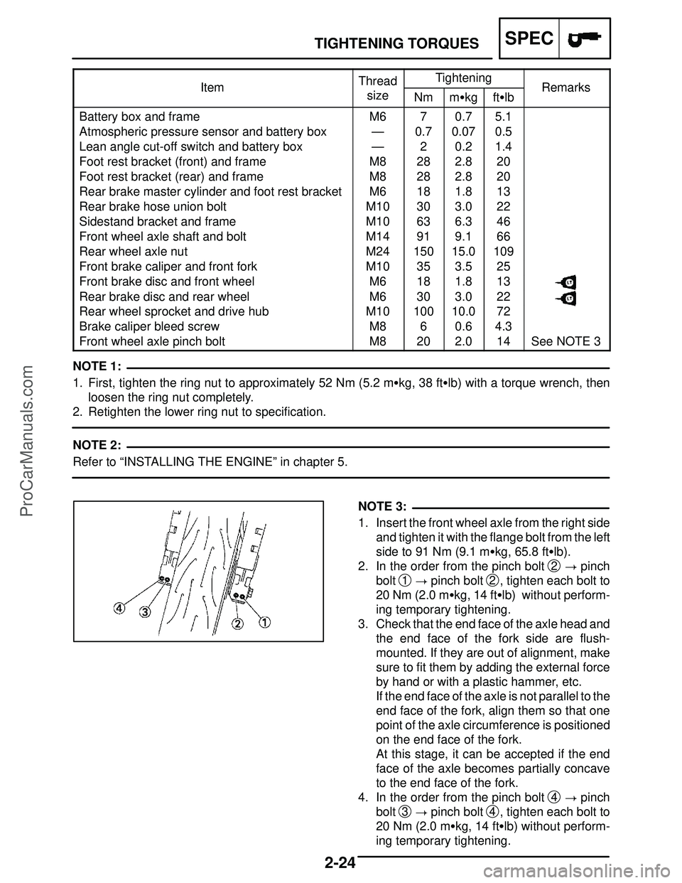
NOTE 3:
ItemThreadTighteningRemarksItemsizeNmm�kgft�lbRemarks
Battery box and frameM670.75.1
Atmospheric pressure sensor and battery box—0.70.070.5
Lean angle cut-off switch and battery box—20.21.4
Foot rest bracket (front) and frameM8282.820
Foot rest bracket (rear) and frameM8282.820
Rear brake master cylinder and foot rest bracketM6181.813
Rear brake hose union boltM10303.022
Sidestand bracket and frameM10636.346
Front wheel axle shaft and boltM14919.166
Rear wheel axle nutM2415015.0109
Front brake caliper and front forkM10353.525
Front brake disc and front wheelM6181.813
Rear brake disc and rear wheelM6303.022
Rear wheel sprocket and drive hubM1010010.072
Brake caliper bleed screwM860.64.3
Front wheel axle pinch boltM8202.014See NOTE 3
1. First, tighten the ring nut to approximately 52 Nm (5.2 m�kg, 38 ft�lb) with a torque wrench, then
loosen the ring nut completely.
2. Retighten the lower ring nut to specification.
Refer to “INSTALLING THE ENGINE” in chapter 5.
1. Insert the front wheel axle from the right side
and tighten it with the flange bolt from the left
side to 91 Nm (9.1 m�kg, 65.8 ft�lb).
2. In the order from the pinch bolt
2 � pinch
bolt
1 � pinch bolt 2, tighten each bolt to
20 Nm (2.0 m�kg, 14 ft�lb) without perform-
ing temporary tightening.
3. Check that the end face of the axle head and
the end face of the fork side are flush-
mounted. If they are out of alignment, make
sure to fit them by adding the external force
by hand or with a plastic hammer, etc.
If the end face of the axle is not parallel to the
end face of the fork, align them so that one
point of the axle circumference is positioned
on the end face of the fork.
At this stage, it can be accepted if the end
face of the axle becomes partially concave
to the end face of the fork.
4. In the order from the pinch bolt
4 � pinch
bolt
3 � pinch bolt 4, tighten each bolt to
20 Nm (2.0 m�kg, 14 ft�lb) without perform-
ing temporary tightening.
ProCarManuals.com
4-71
SWINGARM AND DRIVE CHAINCHAS
WARNING
NOTE:
NOTE:
EAS00703
REMOVING THE SWINGARM
1. Stand the motorcycle on a level surface.
Securely support the motorcycle so that
there is no danger of it falling over.
Place the motorcycle on a suitable stand so that
the rear wheel is elevated.
2. Remove:
�relay arm-to-swingarm bolt
1
�connecting arm bolt 2
�rear shock absorber assembly lower bolt 3
When removing the rear shock absorber as-
sembly lower bolt, hold the swingarm so that it
does not drop down.
3. Measure:
�swingarm side play
�swingarm vertical movement
a. Measure the tightening torque of the pivot
shaft nut.
Pivot shaft nut
105 Nm (10.5 m�kg, 76 ft�lb)
b. Measure the swingarm side play
A by mov-
ing the swingarm from side to side.
c. If the swingarm side play is out of specifica-
tion, check the spacers, bearings, washers,
and dust covers.
Swingarm side play
(at the end of the swingarm)
1.0 mm (0.04 in)
d. Check the swingarm vertical movement
B
by moving the swingarm up and down.
If swingarm vertical movement is not smooth
or if there is binding, check the spacers,
bearings, washers, and dust covers.
ProCarManuals.com