Page 260 of 457
5-38
STARTER CLUTCH AND GENERATORENG
NOTE: REMOVING THE GENERATOR
1. Remove:
�rider seat
�fuel tank
Refer to “SEATS” and “FUEL TANK” in chapter
3.
2. Remove:
�left side cowling
�bottom cowlings
Refer to “COWLINGS” in chapter 3.
3. Drain:
�engine oil
Refer to “CHANGING THE ENGINE OIL” in
chapter 3.
4. Remove:
�plug
�generator rotor cover
1
�While pushing generator rotor, remove the
generator rotor cover.
�Loosen each bolt 1 / 4 of a turn a time, in stages
and in a crisscross pattern.
�After all of the bolts are fully loosened, remove
them.
5. Remove:
�generator rotor and starter clutch assembly
1.
6. Remove:
�idler gear shaft bolt
1
�idler shaft
�idler gear
2
ProCarManuals.com
Page 264 of 457
5-42
STARTER CLUTCH AND GENERATORENG
12 Nm (1.2 m�kg, 8.7 ft�lb)
22 Nm (2.2 m�kg, 16 ft�lb)
NOTE: 3. Install:
�generator cover gasket
�generator cover
1
(M6 bolts)
(M8 bolts)
�First tighten the M8 bolts and then tighten the
M6 bolts.
�Tighten the generator rotor cover bolts in
stages and in a crisscross pattern.
4. Fill:
�engine oil
Refer to “CHANGING THE ENGINE OIL” in
chapter 3.
5. Install:
�bottom cowling
�left side cowling
Refer to “COWLINGS” in chapter 3.
6. Install:
�fuel tank
�rider seat
Refer to “SEATS” and “FUEL TANK” in chap-
ter 3.
ProCarManuals.com
Page 266 of 457

10 Nm (1.0 m�kg, 7.2 ft�lb)
REMOVING THE CRANKSHAFT POSITION
SENSOR
1. Remove:
�rider seat
�fuel tank
Refer to “SEATS” and “")
5-44
CRANKSHAFT POSITION SENSORENG
NOTE:
12 Nm (1.2 m�kg, 8.7 ft�lb)
10 Nm (1.0 m�kg, 7.2 ft�lb)
REMOVING THE CRANKSHAFT POSITION
SENSOR
1. Remove:
�rider seat
�fuel tank
Refer to “SEATS” and “FUEL TANK” in chap-
ter 3.
2. Remove:
�right side cowling
�bottom cowlings
Refer to “COWLINGS” in chapter 3.
3. Drain:
�engine oil
Refer to “CHANGING THE ENGINE OIL” in
chapter 3.
4. Disconnect:
�crankshaft position sensor lead coupler
5. Remove:
�crankshaft position sensor
�O-ring
�pickup rotor cover
1
Loosen each bolt 1 / 4 of a turn a time, in stages
and in a crisscross pattern.
After all of the bolts are fully loosened, remove
them.
INSTALLING THE CRANKSHAFT POSITION
SENSOR
1. Install:
�gasket
New
�pickup rotor cover
1
�O-ring New
�crankshaft position sensor
LOCTITE
2. Connect:
�crankshaft position sensor lead coupler
3. Fill:
�engine oil
Refer to “CHANGING THE ENGINE OIL” in
chapter 3.
4. Install:
�right side cowling
�bottom cowlings
Refer to “COWLINGS” in chapter 3.
ProCarManuals.com
Page 272 of 457
5-50
CLUTCHENG
NOTE:
EAS00276
REMOVING THE CLUTCH
1. Remove:
�clutch cover
1
�gasket
Loosen each bolt 1 / 4 of a turn at a time, in
stages and in a crisscross pattern.
After all of the bolts are fully loosened, remove
them.
2. Remove:
�compression spring bolts
1
�compression springs
�pressure plate
2
�pull rod 3
3. Remove:
�friction plate 1
4. Remove:
�clutch plate 1
1
�friction plate 2
5. Straighten the clutch boss nut rib
1.
ProCarManuals.com
Page 278 of 457
5-56
CLUTCHENG
NOTE:
10 Nm (1.0 m�kg, 7.2 ft�lb)
NOTE:
NOTE: 6. Lubricate:
�friction plates
�clutch plates
(with the recommended lubricant)
Recommended lubricant
Engine oil
7. Install:
�friction plate 2
�clutch plate 1
1
8. Install:
�friction plate 1
1
Install the last friction plate shifting half phase.
9. Install:
�bearing
�pull rod
1
�pressure plate 2
�clutch springs
�clutch spring bolts
3
Tighten the clutch spring bolts in stages and in a
crisscross pattern.
10. Install:
�pull lever
In stall the pull lever with the “�” mark facing to-
ward upper side.
ProCarManuals.com
Page 279 of 457
5-57
CLUTCHENG
NOTE:
12 Nm (1.2 m�kg, 8.7 ft�lb)
12 Nm (1.2 m�kg, 8.7 ft�lb)
NOTE: 11. Install:
�clutch cover
�clutch cover gasket
New
�Install the pull rod so that the teeth a face to-
wards the rear of the motorcycle. Then, install
the clutch cover.
�Apply oil onto the bearing.
�Apply molybdenum disulfide grease onto the
pull rod.
�When installing the clutch cover, push the pull
lever and check that the punch mark
a on the
pull lever aligns with the mark
b on the clutch
cover. Make sure that the pull rod teeth and
pull lever shaft pinion gear are engaged.
�Tighten the clutch cover bolts in stages and in
a crisscross pattern.
12. Tighten:
�clutch cover bolts
1
�clutch cover bolt 2
LOCTITE
Tighten the clutch cover bolts in a stages and in
a crisscross pattern.
13. Adjust:
�clutch cable free play
Refer to “ADJUSTING THE CLUTCH
CABLE FREE PLAY” in chapter 3.
ProCarManuals.com
Page 288 of 457
5-66
OIL PAN AND OIL PUMPENG
NOTE:
EAS00362
REMOVING THE OIL PAN
1. Remove:
�oil level switch
1
�oil pan 2
�oil pan gasket
�dowel pins
Loosen each bolt 1 / 4 of a turn at a time, in
stages and in a crisscross pattern. After all of
the bolts are fully loosened, remove them.
CHECKING THE SPROCKET AND CHAIN
1. Check:
�oil / water pump assembly drive sprocket
1
Cracks / damage / wear � Replace the de-
fective part(-s).
2. Check:
�oil / water pump assembly drive chain
1
Damage / stiffness � Replace the oil / water
pump assembly drive chain and oil / water
pump assembly drive sprocket as a set.
ProCarManuals.com
Page 293 of 457
5-71
OIL PAN AND OIL PUMPENG
12 Nm (1.2 m�kg, 8.7 ft�lb)
10 Nm (1.0 m�kg, 7.2 ft�lb)
43Nm (4.3 m�kg, 31 ft�lb)
WARNING
NOTE:
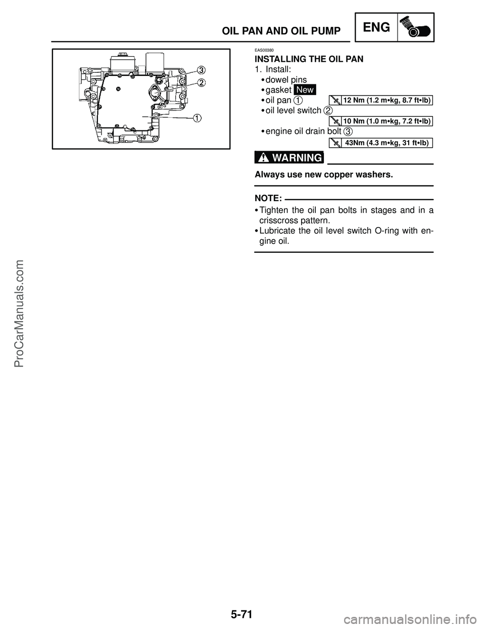
EAS00380
INSTALLING THE OIL PAN
1. Install:
�dowel pins
�gasket
New
�oil pan
1
�oil level switch 2
�engine oil drain bolt 3
Always use new copper washers.
�Tighten the oil pan bolts in stages and in a
crisscross pattern.
�Lubricate the oil level switch O-ring with en-
gine oil.
ProCarManuals.com